

Page 1
Viking Range Corporation
111 Front Street
Greenwood, Mississippi 38930 USA
(662) 455-1200
For product information,
call 1-888-VIKING1 (845-4641)
or visit the Viking Web site at
vikingrange.com
F20481
13040803
(120507J)
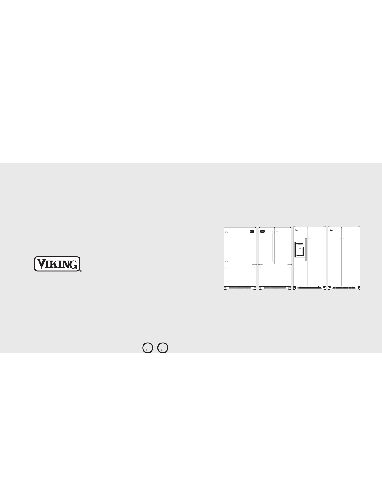
Viking Installation Guide
Freestanding Bottom-Mount/
French Door Bottom-Mount
Side-By-Side Refrigerator/Freezer
U
L
C
U
L
Page 2

Warnings & Important Information____________________________________________________________3
Professional
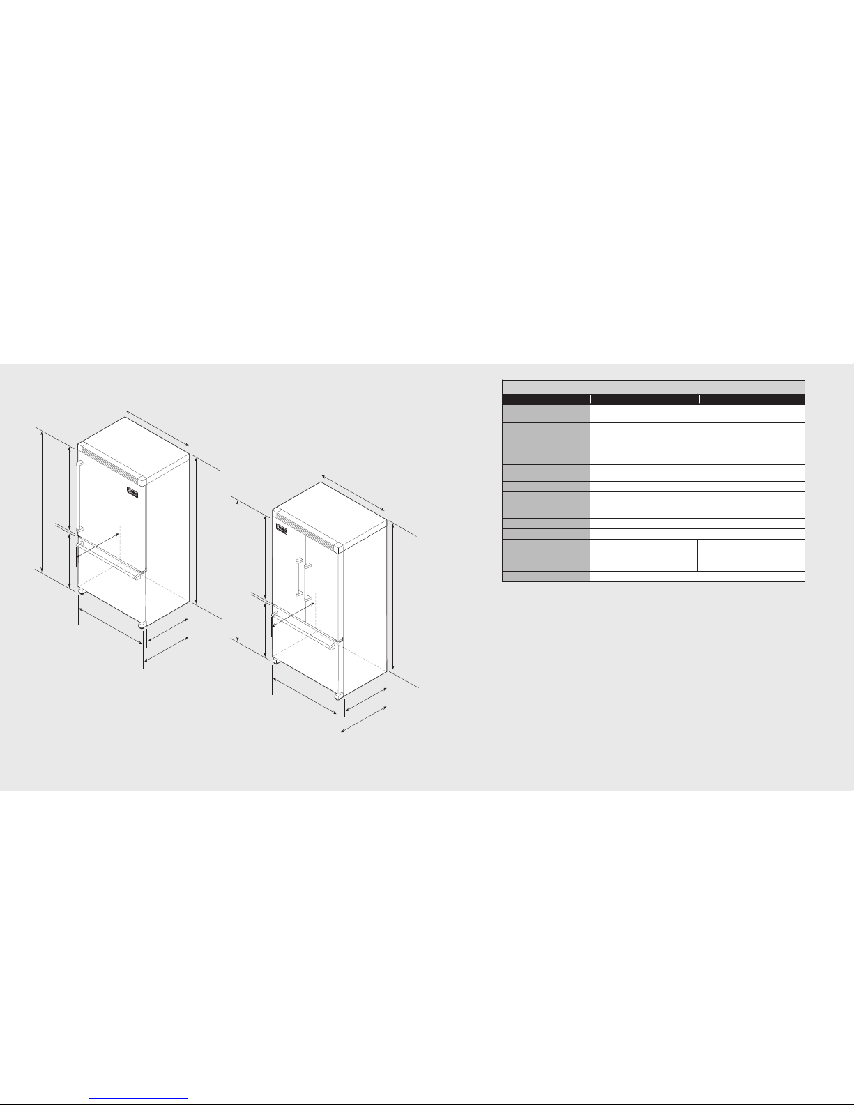
Dimensions (36” Bottom-Mount & French Door Bottom-Mount) __________________________6
Specifications (36” Bottom-Mount & French Door Bottom-Mount) ________________________7
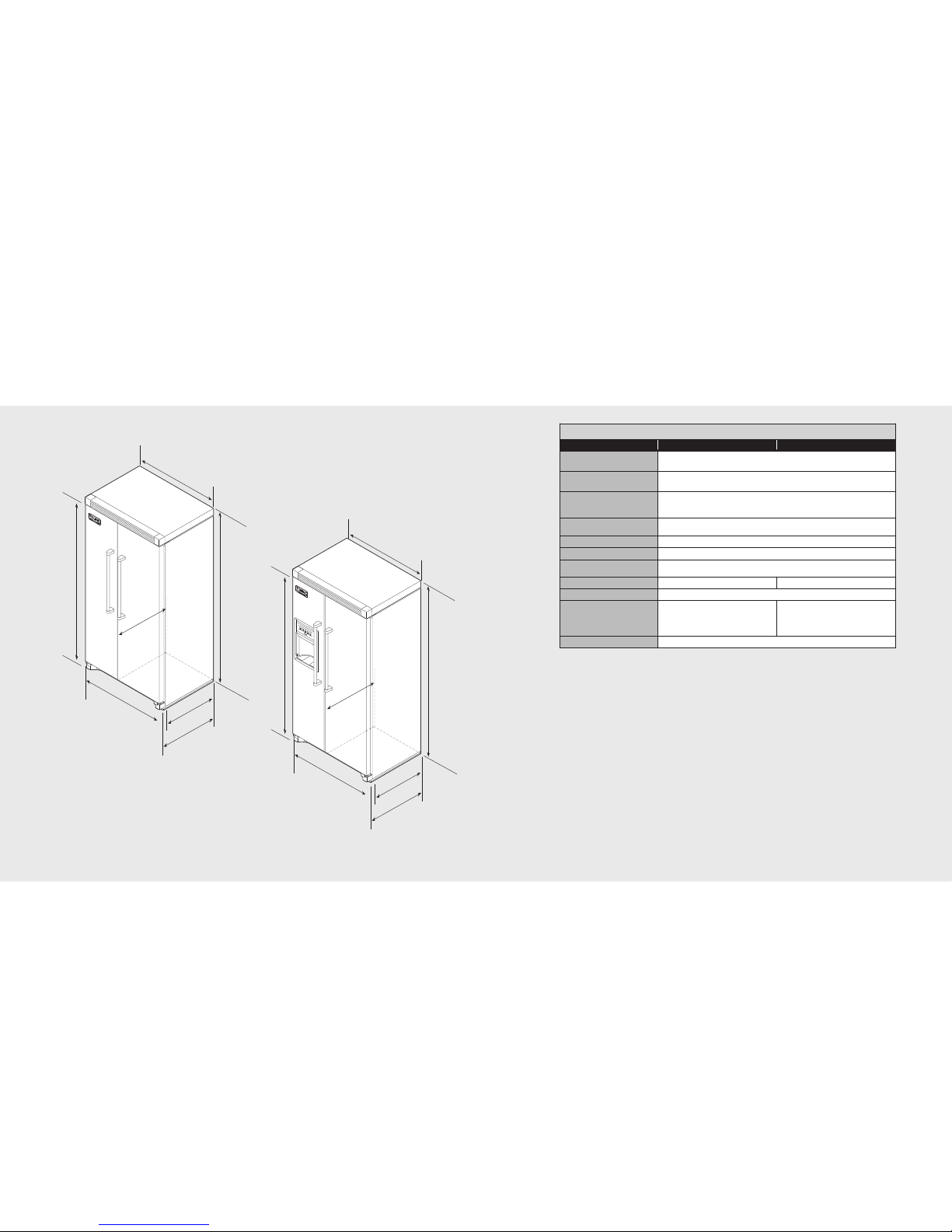
Dimensions (36” Side-By-Side & Side-By-Side with Dispenser) ____________________________8
Specifications (36” Side-By-Side & Side-By-Side with Dispenser) __________________________9
Designer
Dimensions (36” Bottom-Mount & French Door Bottom-Mount) _________________________10
Specifications (36” Bottom-Mount & French Door Bottom-Mount) _______________________11
Dimensions (36” Side-By-Side & Side-By-Side with Dispenser)___________________________12
Specifications (36” Side-By-Side & Side-By-Side with Dispenser)_________________________13
Water Line & Electrical Location_____________________________________________________________14
Important Safety Instructions ________________________________________________________________15
Proper Disposal_____________________________________________________________________________16
General Information_________________________________________________________________________17
Unpacking & Moving____________________________________________________________________17
Water Supply Requirements_____________________________________________________________19
Door & Drawer Removal
Bottom-Mount (Door) ___________________________________________________________________20
French Door Bottom-Mount (Door)______________________________________________________21
Bottom-Mount (Drawer)_________________________________________________________________23
Side-By-Side (Door) _____________________________________________________________________24
Door & Drawer Reinstallation
Bottom-Mount (Door) ___________________________________________________________________27
French Door Bottom-Mount (Door)______________________________________________________28
Bottom-Mount (Drawer)_________________________________________________________________29
Side-By-Side (Door) _____________________________________________________________________30
Installation
Connect to Water Supply _______________________________________________________________32
Leveling (Bottom Mount & French Door Bottom-Mount)_________________________________34
Leveling (Side-By-Side)__________________________________________________________________35
Door Leveling (Side-By-Side & Bottom-Mount) __________________________________________36
Complete the Installation _______________________________________________________________37
Water Filter (Dispenser Models) _________________________________________________________38
Performance Checklist ______________________________________________________________________39
Service & Registration_______________________________________________________________________40
Table of Contents
3
IMPORTANT–Please Read and Follow!
It is the customer’s responsibility to:
• Contact a qualified electrical installer.
• Read all instructions before using the
refrigerator.
• Observe all local codes and ordinances.
Install refrigerator according to installation
instructions. All connections for water,
electrical power and grounding must
comply with local codes and be made by
licensed personnel when required.
• Do not modify plug on power cord. If plug
does not fit electrical outlet, have proper
outlet installed by a qualified technician.
Replace worn power cords and/or loose
plugs.
• Assure that the electrical installation is
adequate and in conformance with the
National Electrical Code, ANSI/NFPA
70-latest edition or Canadian Electrical
Code C22.1-1998 and C22.2 No. 0-M91
(or latest edition), and all local codes and
ordinances. (115 volt, 60-Hz, 15 amp,
fused, electrical supply is required. It is
required that a separate circuit serving only
this appliance be provided. This appliance
is equipped with a power supply cord
having a 3-prong grounding plug. To
minimize possible shock hazard, the cord
must be plugged into a mating 3-prong,
grounding type wall receptacle. If a 2prong receptacle is encountered, the
customer must contact a qualified
electrical installer to have it replaced with a
properly grounded 3-prong receptacle. Do
not use an extension cord or adapter
plug.)
• Do not ground to a gas line or cold-water
pipe.
• Do not remove warning tag from power
cord.
• Refrigerator is designed to operate on a
separate 115 volt, 15 amp., 60 cycle line.
• Do not tamper with refrigerator controls.
• Do not service or replace any part of
refrigerator unless specifically
recommended in Use & Care or Installation
Instructions. Do not attempt service if
instructions are not understood or if they
are beyond personal skill level.
• Always disconnect refrigerator from
electrical supply before attempting to
change light bulbs, clean, or service the
refrigerator. Disconnect the power cord by
grasping the plug, not the cord.
• Always read and follow manufacturer’s
storage and ideal environment instructions
for items being stored in refrigerator.
• Never allow children to operate, play with,
crawl inside or stand on any part of the
refrigerator.
• Never clean refrigerator parts with
flammable fluids. The fumes can create a
fire hazard or explosion.
• Clean up spills or water leakage associated
with water installation.
• Keep your refrigerator in good condition.
Bumping or dropping refrigerator can
damage refrigerator or cause refrigerator
to malfunction or leak. If damage occurs,
have refrigerator checked by qualified
service technician.
2
Page 3
54
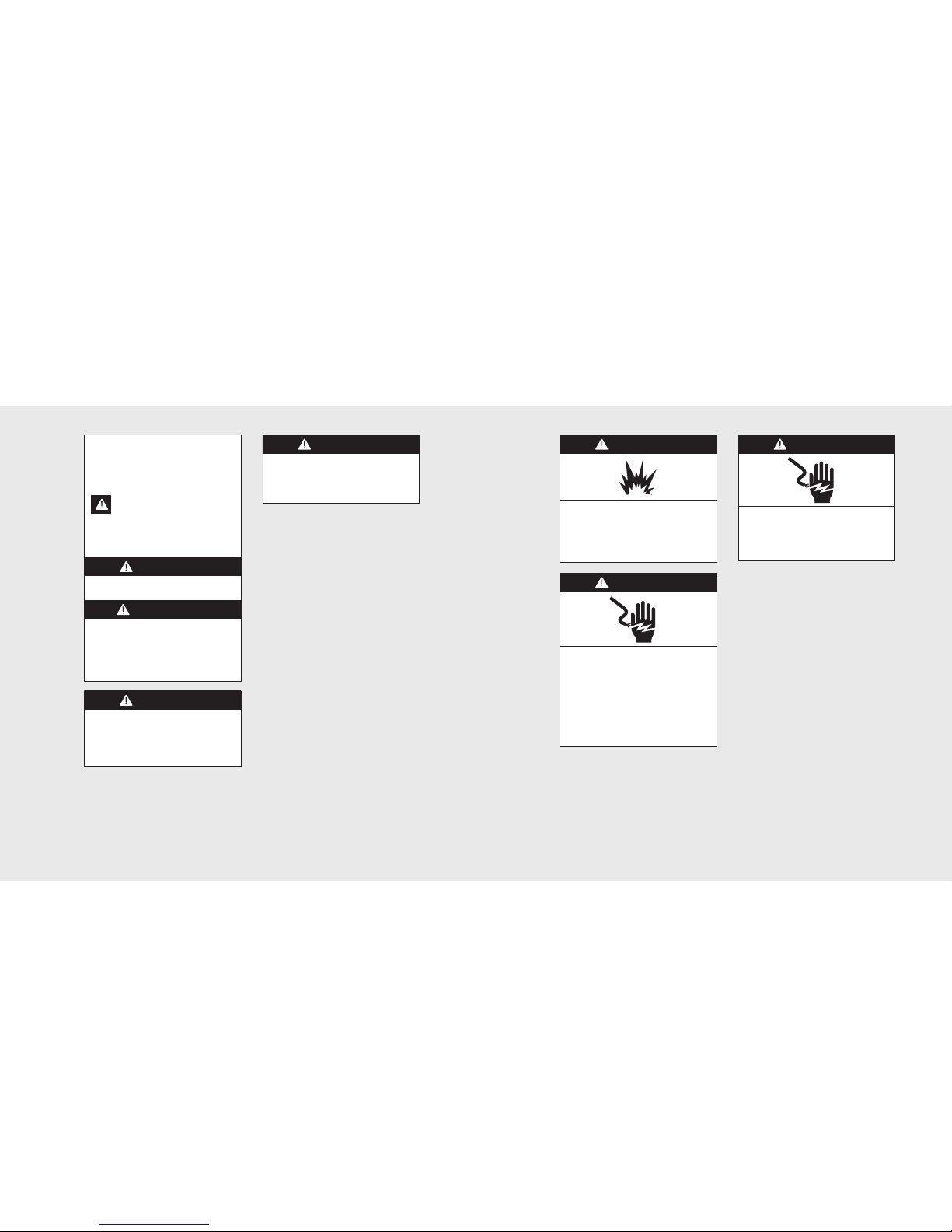
WARNING
Suffocation Hazard
Remove doors from your old refrigerator.
Failure to do so can result in death or
brain damage.
IMPORTANT–Please Read and Follow!
Your safety and the safety of others is
very important.
We have provided many important safety
messages in this manual and on your appliance.
Always read and obeyall safety messages.
This is the safety alert symbol. This
symbol alerts you to hazards that
can kill or hurt you and others.
All safety messages will be preceded by the safety
alert symbol and t he word “DANGER” or
“WARNING”. Thesewords mean:
You can be killed or seriously injured if you
don’t immediately follow instructions.
You can be killed or seriously injured if
you don’t follow instructions.
All safety messages will tell you what the
potential hazard is, tell you how to reduce
the chance of injury, and tell you what can
happen if the instructions are not followed.
DANGER
WARNING
WARNING
Excessive Weight Hazard
Use two or more people to move and
install refrigerator.
Failure to do so can result in back or
other injury.
WARNING
Electrical Shock Hazard
Plug into a grounded 3 prong outlet.
Do not remove ground prong.
Do not use an adapter.
Do not use an extension cord.
Failure to follow these instructions can
result in death, fire, or electrical shock.
WARNING
Explosion Hazard
Keep flammable materials and vapors,
such as gasoline, away from refrigerator.
Failure to do so can result in death,
explosion, or fire.
WARNING
Electrical Shock Hazard
Disconnect power before removing doors.
Failure to do so can result in death or
electrical shock.
IMPORTANT–Please Read and Follow!
Page 4
Specifications (Professional Bottom-Mount)
7
41-1
/
8
”
(
1
0
4
.
5
cm
)
24
”
(
61
.
0
c
m)
70-1/
8”
(
17
8.
1
c
m
)
mi
n
.
to
70-7/
8”
(
18
0.
0
c
m
)
ma
x
.
7
1
-7
/
8
”
(
18
2.
6
cm
)
mi
n
.
to
7
2
-5
/
8
”
(
18
4.
5
cm
)
ma
x
.
3
5
-7
/
8
”
(9
1
.1 c
m
)
w/s
i
d
e
pa
n
el
s
a
c
ce
s
s
o
ry
35-5/
8”
(9
0
.5
c
m)
23-
1/
2”
(59
.7
c
m
)
28-3/
4”
(7
3
.0
c
m)
26-
3/
4”
(6
7
.
9
c
m
)
4
1
-1
/
8
”
(
10
4
.5
c
m)
24
”
(
61
.
0
c
m
)
7
0
-
1
/
8”
(
17
8
.
1
c
m)
mi
n
.
to
7
0
-
7
/
8”
(
18
0
.
0
c
m)
max
.
7
1
-
7/
8
”
(
18
2.
6
cm
)
m
i
n
.
t
o
7
2
-
5/
8
”
(
18
4.
5
cm
)
m
a
x
.
3
5-
7
/
8
”
(
91
.
1
c
m)
w
/si
d
e p
an
e
ls
a
c
ces
s
o
r
y
3
5-5
/8”
(90
.5 c
m
)
23
-
1/2”
(59
.7 c
m
)
26
-
3/4”
(6
7
.9
c
m
)
2
8
-
3
/
4
”
(
73
.
0
c
m
)
Dimensions (Professional Bottom-Mount)
6
36” Bottom-Mount
Description
VCBF036 VCFF036
Overall width 35-5/8” (90.5 cm)
Addition of side panels: 35-7/8” (91.1 cm)
Overall height 70-1/8” (178.1 cm) min. to 70-7/8” (180.0 cm) max.
Addition of top grilles: 71-7/8” (182.6 cm) min. to72-5/8” (184.5 cm) max.
Overall depth from rear To front edge of side trim: 23-1/2” (59.7 cm)
To front edge of top grille: 26-3/4” (67.9 cm)
To front of handle endcap: 28-3/4” (73.0 cm)
Cutout height 70-1/2” (179.0 cm)
Addition of top grilles: 72” (182.9 cm)
Cutout width 36” (91.4 cm)
Cutout depth 24” (61.0 cm)
Electrical requirements 115 volt, 60 Hz, 15 amp dedicated circuit; 3-wire cord with
grounded 3-prong plug attached to product
Maximum amp usage 7.9 amps
Inlet water requirements 1/4” copper tubing inlet waterline; minimum 35 psi; maximum 120 psi
Overall interior capacities
Refrigerator
Freezer
Total capacity
Bottom-Mount
14.4 cu. ft. (407 liters)
5.5 cu. ft. (156 liters)
19.9 cu. ft. (563 liters)
French Door Bottom-Mount
14.1 cu. ft. (399 liters)
5.5 cu. ft. (156 liters)
19.6 cu. ft. (555 liters)
Approximate shipping weight 327 lbs. (148.7 kg)
36” Professional
36” Professional French Door
NOTE: When installing into a cutout, the edge of the door must be 2-7/8” (7.3 cm) from the
adjacent countertop/cabinet.
Page 5
Specifications (Professional Side-By-Side)
9
70-1/
2”
(
17
9.
0
c
m
)
mi
n
.
to
71-1/
4”
(
18
1.
0
c
m
)
ma
x
.
7
1
-
7
/
8
”
(
18
2
.
6
c
m)
mi
n
.
to
7
2
-
5
/
8
”
(
18
4
.
5
c
m)
m
ax
.
3
5
-7
/
8
”
(9
1
.1 c
m)
w/s
i
d
e
p
a
n
e
l
a
c
ce
s
s
o
ry
35-5/
8”
(9
0
.5
c
m)
23-1/
2”
(5
9
.7
c
m)
28-3/
4”
(7
3
.0
c
m)
26-3/
4”
(
67
.
9
cm)
7
0
-1
/
2
”
(
17
9.
0
cm
)
mi
n
.
to
7
1
-1
/
4
”
(
18
1.
0
cm
)
ma
x
.
7
1
-
7/
8
”
(
18
2.
6
cm
)
m
i
n
.
t
o
7
2
-
5/
8
”
(
18
4.
5
cm
)
ma
x
.
3
5-
7
/
8”
(
91
.
1
c
m
)
w
/
s
ide
p
ane
l
a
c
c
es
s
o
r
y
3
5
-5
/
8
”
(90
.5 c
m
)
2
3-1
/2”
(59
.7 c
m
)
2
8
-3
/
4
”
(
73
.
0
c
m)
2
6-
3
/4
”
(6
7
.9
c
m
)
Dimensions (Professional Side-By-Side)
8
36” Professional
36” Professional
with Dispenser
36” Side-By-Side
Description
VCSF036 VCSF036D
Overall width 35-5/8” (90.5 cm)
Addition of side panels: 35-7/8” (91.1 cm)
Overall height 70-1/2” (179.0 cm) min. to 71-1/4” (181.0 cm) max.
Addition of top grilles: 71-7/8” (182.6 cm) min. to72-5/8” (184.5 cm) max.
Overall depth from rear To front edge of side trim: 23-1/2” (59.7 cm)
To front edge of top grille: 26-3/4” (67.9 cm)
To front of handle endcap: 28-3/4” (73.0 cm)
Cutout height 70-1/2” (179.0 cm)
Addition of top grilles: 72” (182.9 cm)
Cutout width 36” (91.4 cm)
Cutout depth 24” (61.0 cm)
Electrical requirements 115 volt, 60 Hz, 15 amp dedicated circuit; 3-wire cord with
grounded 3-prong plug attached to product
Maximum amp usage 7.8 amps 9.4 amps
Inlet water requirements 1/4” copper tubing inlet waterline; minimum 35 psi; maximum 120 psi
Overall interior capacities
Refrigerator
Freezer
Total capacity
13.5 cu. ft. (382 liters)
8.0 cu. ft. (226 liters)
21.5 cu. ft. (608 liters)
13.5 cu. ft. (382 liters)
8.1 cu. ft. (229 liters)
21.6 cu. ft. (611 liters)
Approximate shipping weight 314 lbs. (141.3 kg)
NOTE: When installing into a cutout, the edge of the door must be 2-7/8” (7.3 cm) from the
adjacent countertop/cabinet.
Page 6
11
41-1
/
8
”
(
1
0
4
.
5
cm
)
24
”
(
61
.
0
c
m)
70-1/
8”
(
17
8.
1
c
m
)
mi
n
.
to
70-7/
8”
(
18
0.
0
c
m
)
ma
x
.
7
1
-
7
/
8
”
(
18
2
.
6
c
m)
mi
n
.
to
7
2
-
5
/
8
”
(
18
4
.
5
c
m)
m
ax
.
3
5
-7
/
8
”
(9
1
.1 c
m
)
w/s
i
d
e
pa
n
el
s
a
c
c
es
s
o
ry
35-5/
8”
(9
0
.5
c
m)
23-
1/
2”
(59
.7
c
m
)
26-
3/
4”
(
67
.9
cm
)
4
1
-1
/
8
”
(
10
4.
5
cm
)
24
”
(
61
.
0
c
m)
7
0
-1
/
8
”
(
17
8.
1
cm
)
mi
n
.
to
7
0
-7
/
8
”
(
18
0.
0
cm
)
ma
x
.
7
1
-
7/
8
”
(
18
2.
6
cm
)
m
i
n
.
t
o
7
2
-
5/
8
”
(
18
4.
5
cm
)
m
a
x
.
3
5-
7
/
8”
(
91
.
1
c
m
)
w
/
s
i
d
e
p
a
n
els
a
c
c
e
s
s
o
r
y
3
5-5
/
8
”
(90
.5 c
m
)
2
3-1
/2”
(59
.
7 c
m
)
2
6-
3
/4”
(6
7
.9
c
m
)
28-3/
4”
(7
3
.0
c
m)
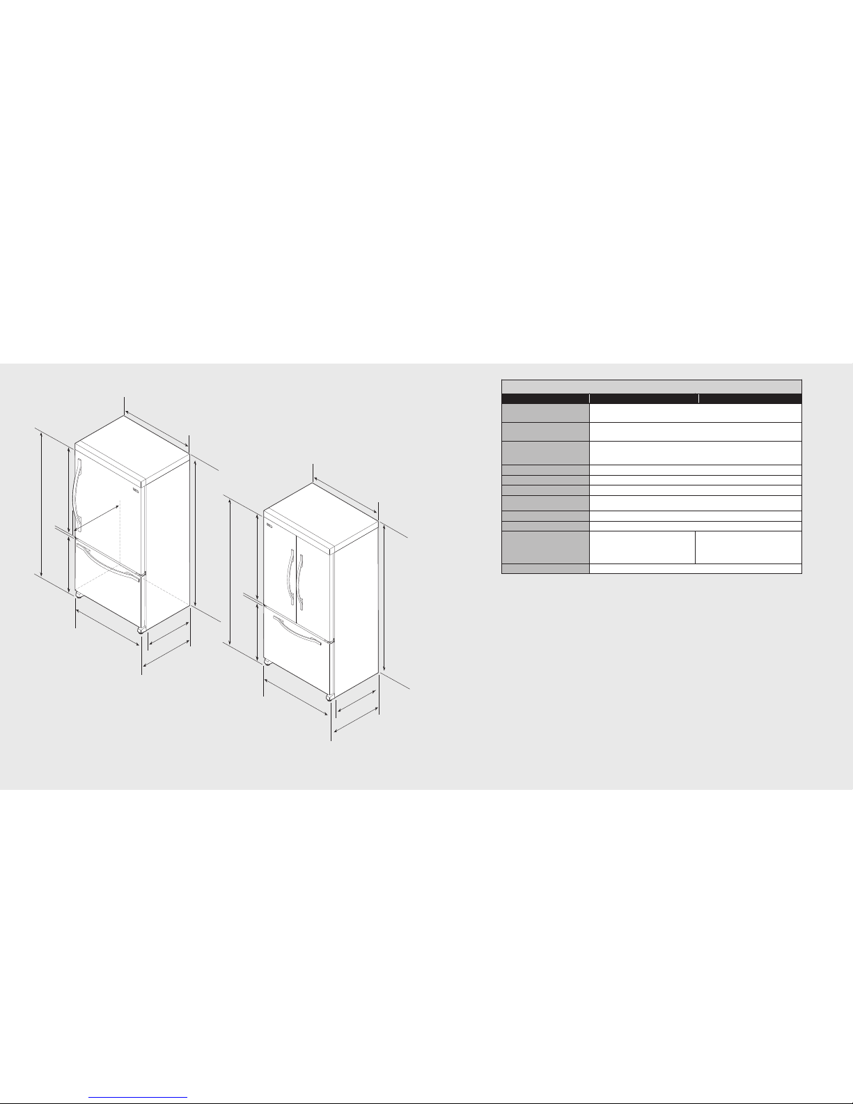
Dimensions (Designer Bottom-Mount)
10
36” Designer
36” Designer French Door
36” Bottom-Mount
Description
DDFB036 DDFF036
Overall width 35-5/8” (90.5 cm)
Addition of side panels: 35-7/8” (91.1 cm)
Overall height 70-1/8” (178.1 cm) min.to 70-7/8” (180.0 cm) max.
Addition of top grilles: 71-7/8” (182.6 cm) min. to72-5/8” (184.5 cm) max.
Overall depth from rear To front edge of side trim: 23-1/2” (59.7 cm)
To front edge of top grille: 26-3/4” (67.9 cm)
To front of handle endcap: 28-3/8” (72.1 cm)
Cutout height 70-1/2” (179.0 cm)
Cutout width 36” (91.4 cm)
Cutout depth 24” (61.0 cm)
Electrical requirements 115 volt, 60 Hz, 15 amp dedicated circuit; 3-wire cord with
grounded 3-prong plug attached to product
Maximum amp usage 7.9 amps
Inlet water requirements 1/4” copper tubing inlet waterline; minimum 35 psi; maximum 120 psi
Overall interior capacities
Refrigerator
Freezer
Total capacity
Bottom-Mount
14.4 cu. ft. (407 liters)
5.5 cu. ft. (156 liters)
19.9 cu. ft. (563 liters)
French Door Bottom-Mount
14.1 cu. ft. (399 liters)
5.5 cu. ft. (156 liters)
19.6 cu. ft. (555 liters)
Approximate shipping weight 327 lbs. (148.7 kg)
Specifications (Designer Bottom-Mount)
NOTE: When installing into a cutout, the edge of the door must be 2-7/8” (7.3 cm) from the
adjacent countertop/cabinet.
Page 7
Specifications (Designer Side-By-Side)
13
70-1/
8”
(
17
8.
1
c
m
)
mi
n
.
to
70-7/
8”
(
18
0.
0
c
m
)
ma
x
.
7
1
-
7
/
8
”
(
18
2
.
6
c
m)
mi
n
.
to
7
2
-
5
/
8
”
(
18
4
.
5
c
m)
m
ax
.
3
5
-7
/
8
”
(9
1
.1 c
m)
w/s
i
d
e
p
a
n
e
l
a
c
ce
ss
o
ry
35-5/
8”
(9
0
.5
c
m)
23-1/
2”
(5
9
.7
c
m)
28-3/
8”
(7
2
.1
c
m)
26-3/
4”
(
67
.9
cm)
7
0
-1
/
8
”
(
17
8.
1
cm
)
mi
n
.
to
7
0
-7
/
8
”
(
18
0.
0
cm
)
ma
x
7
1
-
7/
8
”
(
18
2.
6
cm
)
m
i
n
.
t
o
7
2
-
5/
8
”
(
18
4.
5
cm
)
m
a
x.
3
5-
7
/
8”
(
91
.
1
c
m
)
w
/
s
ide
p
ane
l
a
c
c
es
s
o
r
y
3
5
-5
/
8
”
(90
.5 c
m
)
2
3-
1
/2”
(59
.7 c
m
)
2
6-
3
/4”
(6
7
.9
c
m
)
2
8
-3
/
8
”
(
72
.
1
c
m)
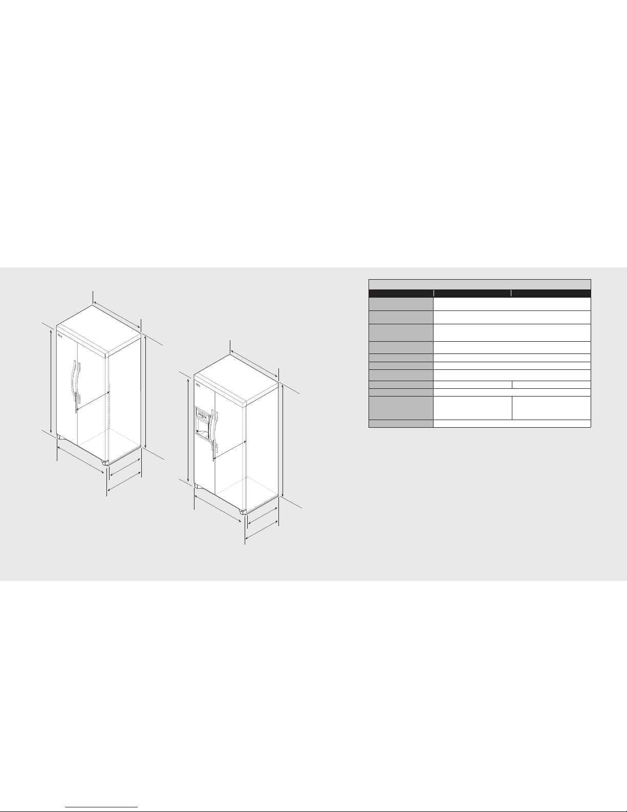
Dimensions (Designer Side-By-Side)
12
36” Side-By-Side
Description
DDSF036 DDSF036D
Overall width 35-5/8” (90.5 cm)
Addition of side panels: 35-7/8” (91.1 cm)
Overall height 70-1/2” (179.0 cm) min. to 71-1/4”(181.0 cm) max.
Addition of top grilles: 71-7/8” (182.6 cm) min. to72-5/8” (184.5 cm) max.
Overall depth from rear To front edge of side trim: 23-1/2” (59.7 cm)
To front edge of top grille: 26-3/4” (67.9 cm)
To front of handle endcap: 28-3/8” (72.1 cm)
Cutout height 70-1/2” (179.0 cm)
Addition of top grilles: 72” (182.9 cm)
Cutout width 36” (91.4 cm)
Cutout depth 24” (61.0 cm)
Electrical requirements 115 volt, 60 Hz, 15 ampdedicated circuit; 3-wire cord with
grounded 3-prong plug attached to product
Maximum amp usage 7.8 amps 9.4 amps
Inlet water requirements 1/4” copper tubing inlet waterline; minimum35 psi; maximum 120 psi
Overall interior capacities
Refrigerator
Freezer
Total capacity
13.5 cu. ft. (382 liters)
8.0 cu. ft. (226 liters)
21.5 cu. ft. (608 liters)
13.5 cu. ft. (382 liters)
8.1 cu. ft. (229 liters)
21.6 cu. ft. (611 liters)
Approximate shipping weight 314 lbs. (141.3 kg)
36” Designer
36” Designer
with Dispenser
NOTE: When installing into a cutout, the edge of the door must be 2-7/8” (7.3 cm) from the
adjacent countertop/cabinet.
Page 8

Important Safety Instructions
15
70-1/2”
(179.1 cm)
cutout without
addition of
tops/grilles
72”
(182.9 cm)
cutout with
addition of
tops/grilles
26”
(66.0 cm)
24”
(61.0 cm)
min.
36”
(91.4 cm)
14”
(35.6 cm)
Water line
location
Recommended
receptacle location
20”
(50.8 cm)
20”
(50.8 cm)
36”
(91.4 cm)
42”
(106.7 cm)
26”
(66.0 cm)
Water Line & Electrical Location
14
• Plug into a grounded 3 prong outlet.
• Do not remove ground prong.
• Do not use an adapter.
• Do not use an extension cord.
• Disconnect power before servicing.
• Replace all parts and panels before operating.
• Remove doors from your old refrigerator.
• Use nonflammable cleaner.
• Keep flammable materials and vapors, such as gasoline, away from refrigerator.
• Use two or more people to move and install refrigerator.
• Disconnect power before installing ice maker (on ice maker kit ready models only).
WARNING: To reduce the risk of fire, electric shock, or injury to persons when using the
refrigerator, follow basic precautions, including the following:
SAVE THESE INSTRUCTIONS
Page 9

Proper Disposal (of old refrigerator)
16 17
General Information
Unpacking Unit
Your refrigerator was packed carefully for
shipment. Remove and discard all packaging
and tape. Do not remove the model/serial
number label.
When moving Your Refrigerator:
Your refrigerator is heavy. When moving the
refrigerator for cleaning or service, be sure to
protect the floor. Always pull the refrigerator
straight out when moving it. Do not wiggle or
“walk” the refrigerator when trying to move it,
as floor damage could occur.
Location
• Do not install refrigerator near oven, radiator
or other heat sources. If not possible, shield
refrigerator material.
• Do not install where the temperature falls
below 55°F (13°C) or rises above 110°F
(43°C). Malfunctions can occur at these
temperatures.
• Refrigerator is designed for indoor
household application only.
Measuring the Opening
When installing your refrigerator, measure
carefully. Allow 1/2” (1.3 cm) space at top
and 1/2” (1.3 cm) behind the machine
compartment cover (located in the rear) for
proper air circulation. Sub-flooring or floor
coverings (i.e. carpet, tile, wood floors,
rugs) may make your opening smaller than
anticipated. Some clearance may be gained by
using the levelingprocedure under “Leveling”.
When installing your refrigerator next to a
fixed wall, leave 2 7/8” (7.3 cm)minimum on
the hinge side to allow for the doorto swing
open.
Before You Throw Away Your Old Refrigerator or Freezer:
• Take off the doors.
• Leave the shelves in place so that children may not easily climb inside.
IMPORTANT:
Child entrapment and suffocation are not problems of the past. Junked or abandoned refrigerators are still
dangerous - even if they will sit for “just a few days.” If you are getting rid of your old refrigerator, please
follow these instructions to help prevent accidents.
WARNING
Suffocation Hazard
Remove doors from your old refrigerator.
Failure to do so can result in death or brain damage.
WARNING
Excessive Weight Hazard
Use two or more people to move and
install refrigerator.
Failure to do so can result in back or other
injury.
WARNING
Explosion Hazard
Keep flammable materials and vapors,
such as gasoline, away from refrigerator.
Failure to do so can result in death,
explosion, or fire.
Page 10

General Information
Water Supply Requirements
A cold water supply with water pressure of
between 35 and 120 psi (241 and 827 kPa) is
required to operate the water dispenser and
ice maker. If you have questions about your
water pressure, call a licensed, qualified
plumber.
Reverse Osmosis Water Supply
IMPORTANT: The pressure of the water
supply coming out of a reverse osmosis
system going to the water inlet valve of the
refrigerator needs to be between 35 and
120 psi (241 and 827 kPa).
If a reverse osmosis water filtration system is
connected to your cold water supply, the
water pressure to the reverse osmosis
system needs to be a minimum of 40 to 60
psi (276 to 414 kPa).
If the water pressure to the reverse osmosis
system is less than 40 to 60 psi (276 to 414
kPa):
• Check to see whether the sediment filter in
the reverse osmosis system is blocked .
Replace the filter if necessary.
• Allow the storage tank o n the rev erse
osmosis system to refill afer heavy usage.
• If your refrigerator has a water filter, it may
further reduce the water pressure when
used in conjunction with a reverse osmosis
system. Remove the water filter.
If yo u have questions about your water
pressure, call a licensed, qualified plumber.
1918
Moving Unit
• NEVER transport the refrigerator on its side.If
an upright position is not possible, lay the
refrigerator on its back. Allow refrigerator to
sit upright for approximately 30 minutes
before plugging it in to assure oil returns to
the compressor. Plugging the refrigerator in
immediately may cause damage to internal
parts.
• Use a n a ppliance d olly when moving
refrigerator. ALWAYS truck refrigerator from
its side or back - NEVER from its front.
• Protect outside finish of refrigerator during
transport by wrapping cabinet in blankets
or insertingpadding between the refrigerator
and dolly.
• Secure refrigerator to dolly firmly with straps
or bungee cords. Thread straps through
handles when possible. Do not overtighten.
Overtightening restraints may dent or
damage outside finish.
Electrical Requirements
Before you move your refrigerator to its final
location, it is important to make sure you
have the proper electrical connection.
Recommended Grounding Method
A 115 Volt, 60 Hz., AC only 15- or 20-amp
fused, grounded electrical supply is required.
It is recommended that a separate circuit
serving only your refrigerator be provided.
Use an outlet that cannot be turned of by a
switch. Do not use an extension cord.
NOTE: Befo re perfor ming any type of
installation, cleaning, or removing a light
bulb, turn the refrigerator OFF. Press the
freezer Down Arrow control until a dash (-)
appears in both the Freezer and Refrigerator
displays. Disconnect the refrigerator from the
electrical source. When you are finished,
reconnect the refrigerator to the electrical
source and reset the temperature controls to
the desired setting.
General Information
WARNING
Electrical Shock Hazard
Plug into a grounded 3 prong outlet.
Do not remove ground prong.
Do not use an adapter.
Do not use an extension cord.
Failure to follow these instructions can
result in death, fire, or electrical shock.
Page 11

21
Some installations require
door/drawer removal to transport
the refrigerator to its final location.
Make sure power cord
is disconnected from
power source.
1
Remove toe grille. Graspfir mly and pulloutward to
unclip.
2
Remove top hinge coversfrom refrigerator doors.
Retain screws and covers for later use.
Door Removal (French Door Bottom-Mount)
20
Some installations require
door/drawer removal to transport
the refrigerator to its final location.
Make sure power cord
is disconnected from
power source.
1
Remove toe grille.
2
3
Remove top hinge coverfrom refrigerator door.
Retain screw and cover for later use.
Unscrew 5/16” hex head screwsfrom top hinge and
remove hinge. Retain all screwsfor later use.
4
Lift refrigerator door from centerhinge pin.
Remove plastic sleeve, ifpresent.
Door Removal (Bottom-Mount)
5
Remove screws to remove centerhinge.
Retain screws for later use
WARNING
Disconnect power before removing doors.
Failure to do so can result in death or
electrical shock.
Door and Drawer Removal
Electrical Shock Hazard
WARNING
Disconnect power before removing doors.
Failure to do so can result in death or
electrical shock.
Electrical Shock Hazard
Page 12

23
1
Pull drawer open tofull extension.
2
Loosen the four screws attaching thedrawer glides to
the drawer front on both sides.
NOTE: Loosen screws three tofour turns. Keep the
screws in the drawerfront.
3
4
Lift drawer front upward andoff the screws.
Push both rails backin.
Freezer Drawer Removal (Bottom-Mount)
22
6
7
Unscrew 5/16” hex head screwsfrom left top hinge.
Retain all screws for later use.
Lift left side refrigerator door, along with tophinge,
from center hinge pin.
8
Remove screws to remove rightand left hinges.
Retain all screws for later use.
4
5
Lift right side refrigerator door fromcenter hinge pin.
Remove door closure from centerhinge pin on the
right side. Retain forlater use.
Disconnect wire harness ontop of left side refrigerator door
top hinge. Release two-pinconnector by pressing junction
point with a flatblade screwdriver or fingernail. Green ground
wire remains attached to thehinge.
3
Unscrew 5/16” hex head screwsfrom right top hinge
and remove hinge. Retain all screws for later use.
Page 13

25
5
Remove top hinge coversby removing Phillips screws.
6
7
Unscrew 5/16” hex head screwsfrom right top hinge
and remove hinge. Retain all screws for later use.
Lift right side refrigerator door fromhinge pin. Remove
door closure from hinge pinon the right side. Retain
for later use.
1
8
9
Disconnect wire harness ontop of left side refrigerator
door top hinge. Releasetwo-pin connector by pressing
junction point with aflat blade screwdriver orfinger nail.
Green ground wire remains attached tothe hinge.
Unscrew 5/16” hex head screwsfrom left top hinge.
Retain all screws for later use.
24
Some installations require
door/drawer removal to transport
the refrigerator to its final location.
Make sure power cord
is disconnected from
power source.
1
Remove toe grille. Graspfir mly and pulloutward to
unclip.
2
3
Open both doors 180°,or as wide as possible.
NOTE: For refrigerators inoperation, shut off water before
removing water line from the door. Push in whitecollar and
hold. Pull the door-side tube from theconnector.
Door Removal (Side-By-Side)
WARNING
Disconnect power before removing doors.
Failure to do so can result in death or
electrical shock.
Electrical Shock Hazard
4
Close doors.
10
Lift left side refrigerator door, along with tophinge,
from hinge pin.
Page 14

2726
11
Remove screws to remove rightand left hinges. Retain
all screws for later use.
5
Replace hinge cover.
6
Replace toe grille.
1
2
Install top hinge looselywith 5/16” hex head screws.
Install center hinge withPhillips screws.
3
4
Place hinge side ofrefrigerator door on center
hinge pin.
While holding refrigerator door upright,tighten down
top hinge with 5/16”hex head drive.
Door Reinstallation (Bottom-Mount)
Page 15

2928
1
Install center hinges withPhillips screws.
Door Reinstallation (French Door Bottom-Mount)
2
Place hinge side ofrefrigerator doors on center
hinge pins.
3
Install top hinges looselywith 5/16” hex head screws.
4
While holding refrigerator doors upright,tighten down
top hinges with 5/16”hex head driver.
5
Reconnect two-pin connector.
6
Replace top hinge covers.
1
2
Pull both rails outto full extension.
Insert the screws in the top of thedrawer front into the
slots in the drawerbrackets.
3
4
Pull the drawer bracketstoward you to positionthe
screw in the bottom of the drawer front into the
brackets. Repeat for bothsides of drawer.
Completely tighten the fourscrews on both sidesof
drawer.
Freezer Drawer Reinstallation (Bottom-Mount)
5
Push drawer closed.
Page 16

31
7
8
Open doors as wideas possible.
Firmly push tube 5/8” into the connector. Use lines on
the tube as aguide for full insertion. NOTE: If water line
tube end is damaged,cut off 5/8” before reconnecting.
If leaking occurs, reconnectthe line.
9
Replace toe grille. Alignthe toe grille mounting clips
with the lower cabinetslots. Push the toe grille firmly
until it snaps intoplace.
30
1
2
Install hinges with Phillipsscrews.
Place hinge side ofrefrigerator doors on hingepins.
3
4
Install top hinges looselywith 5/16” hex head screws.
While holding refrigerator doors upright,tighten down
top hinges with 5/16”hex head driver.
5
6
Reconnect two-pin connector.
Replace top hinge covers.
Door Reinstallation (Side-By-Side)
Page 17

33
5
6
1
2
7
8
Pull on tubing toconfir m connection issecure.
Connect tubing to framewith tubing clamp.
Turnon water supply.Check forleaks and correct if
necessary.Monitor water connectionfor 24hours. Correct
leaksif necessary.
Slide brass nut oversleeve and screw nutinto inlet
port. Place adjustable wrench on nutattached to plastic
waterline and maintain position.
Using second adjustable wrench, turn the lower nut
counterclockwise and fully tighten the upper nut in
place. IMPORTANT: Donot overtighten. Cross
threading may occur.
32
2
4”
di
a.
(
6
0
.9
c
m
)
m
i
n
.
2
4”
di
a.
(
6
0
.9
c
m
)
m
i
n
.
1
2
Create service loop with copper tubing (minimum 2
feet diameter). Avoid kinks in the copper tubingwhen
bending the service loop.Do not use plastic tubing.
Remove plastic cap from water valveinlet port.
Installation
Materials Needed
• 1/4” outer diameter flexible copper tubing
• Shut-off valve (requires a 1/4” hole to be drilled into water supply line before valve
attachment)
• 2 adjustable wrenches
• 1/4” hex nut driver
NOTE: Use copper tubing only for installation. Plastic is less durable and can cause damage.
Add 8 feet to tubing length needed to reach water supply for creation of service loop.
Connect to Water Supply
3
Brass nut
Sleeve
4
Place brass nut andsleeve on copper tube end as
illustrated. Remember: Do notuse old sleeve. The nut
and the sleeve are provided inthe consumer literature
packet.
Place end of coppertubing into water valve inlet port.
Shape tubing slightly.Do not kink—so that tubing
feeds straight into inletport.
Page 18

35
1
2
A
AAA
Remove toe grille.
Grasp firmly and pull outward to unclip.
Using hex head driver, turn the front adjustment screws
“A” on each sideto raise or lower the front of the
refrigerator.
BBB
B
3
4
Using the hex headdriver, turn each of the adjustment
screws “B” to raise or lower the rear of therefrigerator.
Using the carpenter’s level, makesure front of
refrigerator is 1/4” (.06 cm) or approximately half a
bubble higher than backof refrigerator.
Leveling (Side-By-Side)
T
o protect property and refrigerator from damage, observe the following:
• Protect vinyl or other flooring with cardboard, rugs, or other protective material.
• Do not use power tools when performing leveling procedure.
Materials Needed
• 3/8” hex head driver
• Carpenter’s level—To enhance the appearance and maintain performance, the refrigerator should
be level.
• Stabalizing legs are stored in the freezer basket. Install Stabalizing legs by tipping refigerator back
slightly and screwing the legs in clockwise.
NOTE: Complete any required panel installation and/or water supply connection before
leveling. Refrigerator should be in permanent location prior to leveling.
34
1
A
2
Remove toe grill. Graspfir mly and pulloutward
to unclip.
Toraise the front of theunit, turn theleveler footscrew
clockwise.To raise therear of theunit, use a 3/8”hex
head driverto turn each ofthe adjustment screws (A)
clockwise(French Door models only).
NOTE: Having someone pushagainst the topof therefrigerator
takes someweight off theleveler foot screws.
A
3
4
To lower the frontof the unit, turn the leveler footscrew
counterclockwise. To lower therear of theunit, use a 3/8”
hex head driver toturn each of theadjustment screws (A)
counterclockwise (French Door models only).
NOTE: It may take several turns of the leveler foot screw to
adjust the tilt of the refrigerator.
Replace toe grill. Alignthe toe grille mounting clips
with the lower cabinetslots. Push the toe grille firmly
until it snaps intoplace. Check for level.
Leveling (Bottom-Mount & French Door Bottom-Mount)
To protect property and refrigerator from damage, observe the following:
• Protect vinyl or other flooring with cardboard, rugs, or other protective material.
• Do not use power tools when performing leveling procedure.
Materials Needed
• 3/8” hex head driver
• 1/4” hex head driver
• Carpenter’s level
To enhance the appearance and maintain performance, the refrigerator should be level.
NOTE: Complete any required panel installation and/or water supply connection before
leveling. Refrigerator should be in permanent location prior to leveling.
Page 19

37
3
Check with level toverify 1/4” tilt to the back for
proper door closure.
1. Plug into a grounded 3 prong outlet.
NOTE: Allow 24 hours to produce the first batch of ice. Discard the first three batches of ice
produced. Allow 3 days to completely fill the ice container.
36
5
6
Check that refrigerator is level from side to side.
Turn stabilizing legs clockwise until firmly
against floor.
7
A
AAA
8
Turn adjustment screws“A” counter clockwise to allow
the full weight ofthe refrigerator to rest on the
stabilizing legs.
Replace the toe grille.Align the toe grille mounting
clips with the lowercabinet slots. Push the toe grille
firmly until it snaps into place.
Complete the Installation
1
2
A
AAA
Determine which door needs to be raised.
Turn front roller adjustment screws“A” clockwise to
raise front corner ofdoor.
Door Leveling (Side-By-Side & French Door Bottom-Mount)
WARNING
Electrical Shock Hazard
Plug into a grounded 3 prong outlet.
Do not remove ground prong.
Do not use an adapter.
Do not use an extension cord.
Failure to follow these instructions can
result in death, fire, or electrical shock.
Page 20

39
Performance Checklist
h Plug-in unit and verify operation.
h Connect water supply (if applicable).
• Verify icemaker bail arm is down.
• Verify dispenser operation
(if applicable).
h Align/square door(s).
h Verify drain pan properly installed and no
leaks on water connection.
h Remove internal packaging and labels
and wipe unit down.
Installer’s information:
Installer’s name:_____________________________
Installer’s company:_________________________
Date:________________________________________
38
1
2
1
2
Locate water filter compartment.The compartment is
located in the upperright corner of the refrigerator. Push
tab on compartment torelease latch and pulldownward.
Unscrew and remove cover.
1
2
3
4
Side-By-Side
Bottom-Mount
Insert filter cartridge intofilter housing. Rotate
clockwise gently until filterstops.
Close water filter door.
NOTE: Allow 1-2 minutedelay in water dispersal to
allow internal watertank to fill.
Flush air from the system by running waterthrough the
dispenser continuously for 3minutes.
Water Filter Installation (If Applicable)
Page 21

4140
Only authorized replacement parts may be
used in performing service on the appliance.
Do not repair or replace any part of the
appliance unless specifically recommended in
the manual. All other servicing should be
referred to a qualified technician.
Record the following information indicated
below. You will needit ifservice is everrequired.
The serial number and model number for your
appliance are located on the identification plate
mounted on the left wall of the refrigerator
section of the unit.
Model number
_________________________________________
Serial number
_________________________________________
Date of purchase
_________________________________________
Date installed
_________________________________________
Dealer's name
_________________________________________
Address
_________________________________________
Service & Registration
Page 22

4342
Notes Notes
 Loading...