

Viking V36CO Series, VxxG Series, VxxF Series, VxxH Series, VxxT Series Installation, Operation & Owners Manual
...
Installation, Operation & Owners Guide
Models
Oven, Standard
V36SO Series
Oven, Convection
V36CO Series
Open Top Burner
VxxBx series
French Top
VxxF series
Hot Top
VxxH series
Griddles
VxxG,T and P series
Broilers
VxxC series
Viking Range Corporation
Commercial Products Div.
111 Front Street
Greenwood, MS 38930
(877) 307-8877
RETAIN THIS MANUAL FOR FUTURE REFERENCE
016284-000 (07/09)

IMPORTANT FOR YOUR SAFETY… …….
THIS MANUAL HAS BEEN PREPARED FOR PERSONNEL QUALIFIED TO
INSTALL GAS EQUIPMENT, WHO SHOULD PERFORM THE INITIAL FIELD
START-UP AND ADJUSTMENTS OF THE EQUIPMENT COVERED BY THIS
MANUAL.
POST IN A PROMINENT LOCATION THE INSTRUCTIONS TO BE
FOLLOWED IN THE EVENT THE SMELL OF GAS IS DETECTED. THIS
INFORMATION CAN BE OBTAINED FROM THE LOCAL GAS SUPPLIER.
IMPORTANT… …….
IN THE EVENT A GAS ODOR IS DETECTED, SHUT DOWN UNITS AT MAIN
SHUTOFF VALVE AND CONTACT THE LOCAL GAS COMPANY OR GAS
SUPPLIER FOR SERVICE.
FOR YOUR SAFETY… …….
DO NOT STORE OR USE GASOLINE OR OTHER FLAMMABLE VAPORS OR
LIQUIDS IN THE VICINITY OF THIS OR ANY OTHER APPLIANCE.
WARNING… …….
IMPROPER INSTALLATION, ADJUSTMENT, ALTERATION, SERVICE OR
MAINTENANCE CAN CAUSE PROPERTY DAMAGE, INJURY OR DEATH.
READ THE INSTALLATION, OPERATING AND MAINTENANCE
INSTRUCTIONS THOROUGHLY BEFORE INSTALLING OR SERVICING THIS
EQUIPMENT.
IN THE EVENT OF A POWER FAILURE, DO NOT ATTEMPT TO OPERATE
THIS DEVICE.
©2009 Viking Commercial Division
2
Table of Contents
Section 1: Installation …
Appliances Equipped with Casters
Electrical Supply
Gas Supply
Gas Pressure Regulator ……………………………………………………………… 9
Installation Procedure
Clearances……………………………………………………………………………… 4
Location ………………………………………………………………………………… 4
Rating Plate Location..……………………………………………………………...... 6
Riser…………………………………………………………………………………….. 6
Uncrating …………………………………………………………….…………………. 4
Leveling
Statutory Regulations
Canada ….……………………………………………………………………….......... 7
United States of America …………………………………………………………….. 7
Ventilation Air
………………………………………………………………………………………… 5
………………………………………………………………………………. 10
..…………………………………………………………………………………….. 8
……………………………………………………………….………. 4
……………………………………………………………………….. 7
…………………………………………………………………………………. 9
Section 2: Operator Instructions
Lighting Instructions ………………………………………………………………………… 11
Broiler …………………………………………………………………………………. 11
French Top ……………………………………………………………… …………… 11
Griddle Top, Manual and Thermostatic …………………………………………… 11
Griddle Top, Plancha ………………………………………………………………... 11
Hot Top...……………………………………………………………………………… 12
Oven, Standard and Convection …………………………………………………... 12
Sealed Top Burners …………………………………………………………………… 12
Section 3: Cleaning and Maintenance
Broiler …………………………………………………………………………………. 13
Griddles, ALL ………………………………………………………………………… 14
Hot Top / French Top ……………………………………………………………….. 15
Oven …………………………………………………………………………………… 15
Sealed Top Burners …………………………………………………………………. 16
Service ………………………………………………………………………………… 16
Wiring Diagram, Convection Oven………………………………………………….. 17
Section 4: Warranty …
©2009 Viking Commercial Division
…………………………………………………………….. 4
…….…………………………………………………. 7
................................................................... 11
………………………………………… 13
……………………………………………………………… 18
3
Installation
Installation Procedure
Uncrating
Check the crate for any possible damage sustained during transit. Carefully remove the
appliance, removing all packing material, again check for damage. Any damage to the appliance
must be reported to the carrier immediately.
Location
Proper placement of the appliance will ensure operator convenience and satisfactory
performance. Adequate clearance must be maintained so that the combustion and ventilation air
is not obstructed for proper operation. A minimum front clearance of 36 inches (914 mm) must be
provided for servicing. The appliance must be kept free and clear of combustible materials.
Placing Appliance
Place the appliance in the required position and level by means of the adjustable legs or casters.
The floor on which the appliance is to be installed must be capable of adequately supporting the
weight of the appliance.
Clearances
The following minimum clearances must be followed:
COMBUSTIBLE NON-COMBUSTIBLE
Model BACK SIDE BACK SIDE
V36 Oven Standard 6” 12” 0 0
V36C Oven Convection 6” 12” 2” 0
Broiler
French Top 4” 8” 0 0
Griddle 2” 2” 0 0
Hot Top 4” 8” 0 0
Plancha Griddle 2” 6” 0 0
Sealed Burner Top 6” 12” 0 2”
Note: Broilers, for use in noncombustible locations only.
Note: When a Cheesemelter or Salamander is installed on a riser attached to the
oven base, a minimum of 16” side clearance to a combustible surface is
required on all oven bases.
See Note Below See Note Below
©2009 Viking Commercial Division
4
6” 0

Leveling
For proper and safe operation each appliance must be level. The oven base can be mounted on
legs, casters or on a non combustible curb base. Counter units must be installed on a noncombustible surface only.
Legs are mounted using four hex head bolts per leg and each leg is adjustable simply by turning
the inner cylinder leg, clockwise to lower and counter clockwise to elevate. 6” legs are standard
for the oven or cabinet base and 4” legs for counter top units.
Optional; casters are mounted using four hex head bolts per caster; locking casters must be
installed on the front and non-locking on the back. Adjustable casters, the unit can be leveled by
loosening the two set screws in the collar on each caster and turning the collar clockwise to lower
and counter clockwise to elevate. Be sure to retighten the two set screws on each caster when
unit is level to maintain proper adjustment.
When mounting on a non-combustible curb base make sure the base is level prior to putting the
oven base in place. Use non combustible shims, if needed, to stabilize and level the oven.
Note:
A carpenter’s level can be used on the plate shelf for left to right leveling, if the unit has Sealed
Burners, French top, Hot Top, Work Top or Griddle a level can be placed on the flat top surface
for front to rear leveling; on u nits with broilers or double oven use the oven rack for front to rear
leveling.
©2009 Viking Commercial Division
5
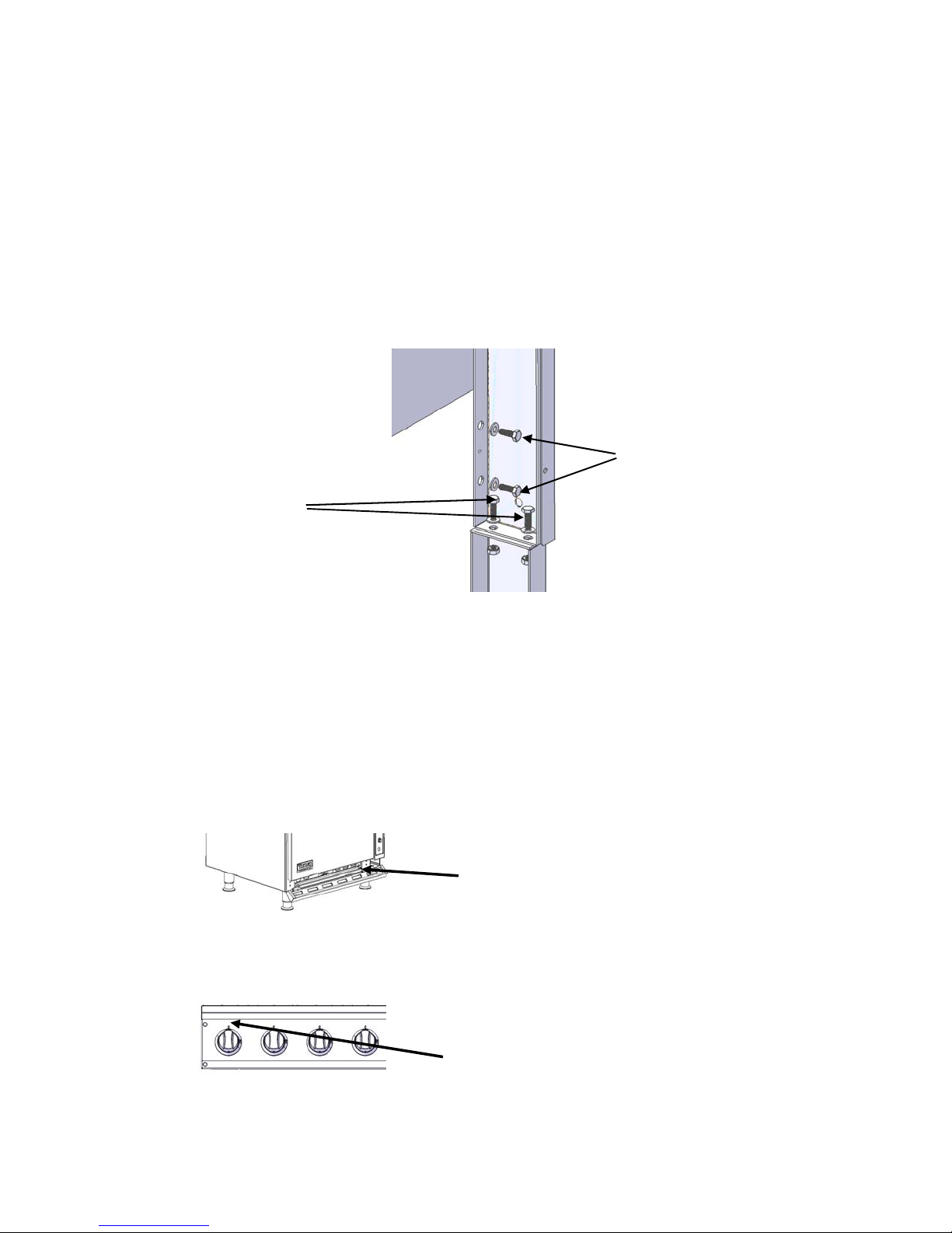
Riser Installation
1) Remove back panel from riser assembly by removing mounting screws
2) Remove the four bolts at the rear of the range top / work top holding on the side panels
(two on each side, see diagram below)
3) Place riser on support brackets on back of oven, cabinet or refrigeration base
4) Reinstall the four bolts into the back of the range top / work top through the riser
channels, do not tighten
5) Attach the bottom supports with supplied bolts, two on each side
6) Tighten the four bolts that attach riser to range top / work top
7) Tighten the four bolts that attach riser to bottom supports
8) Reinstall back cover
Riser Support Bolts
Note:
Failure to reinstall back cover could cause improper venting of exhaust gases from oven and
range tops creating soot to clog burner(s) and flue
Range Top Bolts
Model / Serial / Rating Plate Locations
Oven, All
Behind kick plate on rail, right side
Range tops, Sealed Top Burner, French Top, Hot Top, Griddles (all), and Broiler
On front panel, left side above knob
©2009 Viking Commercial Division
6
Statutory Regulations
The installation of this appliance must be carried out by a properly trained and qualified installer
and in accordance with the relevant regulations, codes of practice and the related publications of
the Country, State, County and City of destination.
In the United Sates of America:
1) Local Codes
2) National Fuel Gas Code ANSI Z223.1 or latest edition. Copies may be obtained from the
American Gas Association, Inc., on their web site: http://www.aga.org/
3) National Electrical Code, ANSI/NFPA-70, or latest edition. Copies may be obtained from
the National Fire Protection Association, on their web site: http://www.nfpa.org/
4) Vapor Removal From Cooking Equipment, NFPA-96, or latest edition. Copies may be
obtained from the National Fire Protection Association, on their web site:
http://www.nfpa.org/
In Canada:
1) Local Codes
2) CSA B149.1 Natural Gas and Propane Installation Code.
3) CSA C22.1 Canadian Electrical Code
4) CSA C22.2 Canadian Electrical Code
Canadian codes can be found on the CSA website: http://www.csa.ca
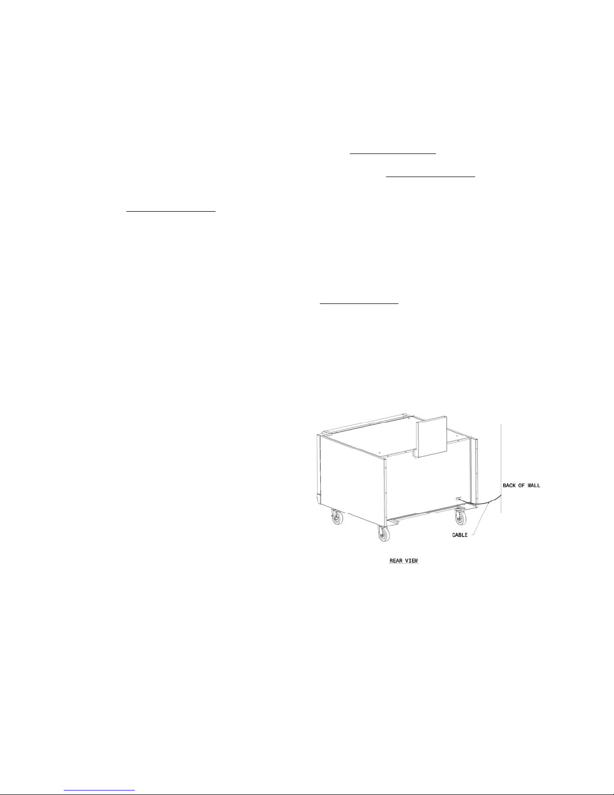
Appliances Equipped with Casters
Note:
The front casters of the appliance are equipped with brakes to limit movement of the appliance
without depending on the connector and any quick-disconnect device or its associated piping to
limit the appliance movement.
1) The installation shall be made with a
connector that complies with the
Standard for Connectors for Movable
Gas Appliances, ANSI Z21.69/CSA
6.16, (or latest edition), and a quickdisconnect device that complies with
Standard for Quick Disconnect of Use
with Gas Fuel, ANZI Z21.41/CSA 6.9,
(or latest edition).
2) Adequate means must be provided to
limit the movement of the appliance
without depending on the connector and
the quick-disconnect device or its
associated piping to limit the appliance
movement. (see fig. 1)
Fig. 1
Note:
Please be aware, required restraint is attached to a bracket, and if disconnection of the restraint
is necessary, be sure to reconnect the restraint after the appliance has been returned to its
original installed position.
©2009 Viking Commercial Division
7

Gas Supply
The local gas authority should be consulted at the installation planning stage in order to establish
the availability of an adequate supply of gas and to ensure that the meter is adequate for the
required flow rate. The pipe work from the meter to the appliance must be an appropriate size.
All fixed (non-mobile) appliances must be fitted with an accessible upstream gas shut off valve as
a means of isolating the appliance for emergency shut off and for servicing. A union or similar
means of disconnection must be provided between the gas-cock and the appliance.
A manually operable valve must be fitted to the gas supply to the kitchen to enable it to be
isolated in an emergency. Wherever practical, this shall be located either outside the kitchen or
near an exit in a readily accessible position.
Where it is not practical to do this, an automatic isolation valve system should be fitted which can
be operated from a readily accessible position near the exit.
In locations where the manual isolation valve is fitted or the automatic system can be reset this
notice must be posted:
“ALL DOWNSTREAM BURNER AND PILOT VALVES MUST BE TURNED OFF PRIOR TO
ATTEMPTING TO RESTORE THE SUPPLY. AFTER EXTENDED SHUT OFF, PURGE
BEFORE RESTORING GAS”
Gas Supply Notes
Before assembly and connection, check gas supply.
• The type of gas for which the unit is equipped is stamped on the data plate, see locations
on page 3. Connect a unit stamped “Natural” only to natural gas and stamped “Propane”
only to propane gas.
• If it is a new installation, have the gas authorities check the meter size and piping to
assure that the unit is supplied with the necessary amount of gas supply and pressure to
operate the unit(s).
• Make certain new piping and connections have been made in a clean manner and have
been purged so that piping compound, chips, etc. will not clog pilots, valves or burners.
Use pipe joint compound approved for natural and liquefied petroleum gases.
©2009 Viking Commercial Division
8
Gas Pressure Regulator
A gas pressure regulator must be installed to regulate the proper flow of gas to the appliance.
The regulator must be installed between the main gas supply line to the unit shut off valve and
the appliance and must be accessible for servicing. Proper sizing of the regulator is extremely
important, check the BTU rating of the appliance or appliances being regulated by the regulator.
Note:
Contact the factory for regulator sizing when multiple appliances are being installed in a line up or
island suite configuration and are interconnected using the front manifold connections.
Note:
Gas pressure should be checked when the unit is installed and all other equipment on the same
line is on. The operating gas pressure must be the same as that specified on the rating plate. If
necessary, pressure adjustment may be made at the pressure regulator.
The appliance and its individual shut-off valve must be disconnected from the gas supply piping
system during any pressure testing of that system where pressures are in excess of ½ PSIG
(3.45KPA).
When test pressures are ½ PSIG (3.45KPA) or less, the range must be isolated from the gas
supply system by closing its individual manual shutoff valve.
Prior to lighting, check all joints in the gas supply line for leaks. Use
soap and water solution. Do not use an open flame. After piping has
been checked for leaks, all piping receiving gas should be fully
purged to remove air.
Ventilation Air
The following notes are intended to give general guidance. For detailed recommendations, refer
to the applicable codes in the Country, State, County and City of installation.
• Do not obstruct the flow of combustion and ventilation air.
Proper ventilation is critical for optimum performance. The ideal method of ventilating gas fired
equipment is the use of properly designed canopy that should extend six inches (152mm) beyond
all sides of the appliance (s) and six feet six inches (1981mm) above the floor. Information on the
construction and installation of ventilating hoods may be obtained from the standard for "Vapor
Removal from Cooking Equipment," NFPA No. 96 (latest edition), available from the National Fire
Protection Association, on their web site: ht tp://www.nfpa.org/.
A strong exhaust will create a vacuum in the room. For an exhaust vent to work properly,
replacement air must be equal to the amount of air exhausted. An imbalance between exhaust
and replacement air can cause degradation in the appliance’s performance.
All gas burners and pilots need sufficient air to operate. Large objects should not be placed in
front of the appliance(s) that would obstruct the flow of air into the front.
©2009 Viking Commercial Division
9

Electrical Supply (Where Applicable)
Important- This appliance must be electrically grounded in accordance with local codes, or in the
absence of local codes with the National Electrical Code.
Appliances equipped with a flexible electrical supply cord are provided
with a three-prong grounding plug. It is imperative that this plug be
connected into a properly grounded three-prong receptacle. If the
receptacle is not the proper grounding type, contact an electrician. Do
not remove the grounding prong from this plug.
The convection range is designed for 120 volt power supply, 15amp circuit and is provided with a
flexible electric supply cord and plug that must be plugged into the proper receptacle. Do not
connect the convection range to electrical supply until after gas connections have been made.
The wiring diagram for the convection range is located behind the front control panel.
©2009 Viking Commercial Division
10
Operator Instruction’s
Lighting Instructions
Broiler
For daily shutoff: Turn burner valve knob(s) to the “OFF” position, pilot(s) will remain on.
French Top
For daily shutoff: Turn burner valve knob to the “OFF” position, pilot will remain on.
Griddle Top, Manual and Thermostatic
For daily shutoff: Turn burner valve knob(s) to the “OFF” position, pilot(s) will remain on.
Griddle Top, Plancha
For daily shutoff: Turn burner valve knob(s) to the “OFF” position, pilot(s) will remain on.
©2009 Viking Commercial Division
1) Remove grates and their supporting frames, remove radiants.
2) Turn main gas supply on.
3) Turn burner valve knobs to the “ON” position for 5 seconds to purge the air in the gas
lines, if there is no gas present wait 5 minutes and repeat the operation.
4) As soon as gas is present turn the burner valve knobs to the “OFF” position.
5) Using a log lighter, light the pilot (s).
6) Wait 3 minutes.
7) Turn all of the burners on and then off, one at a time, to make sure all of the lines have
been purged of air.
8) Reinstall the radiants, supporting frames and grates.
1) Remove center ring from French Top.
2) Turn main gas supply on.
3) Turn burner valve knob to the “ON” position for 5 seconds to purge the air in the gas
lines, if there is no gas present wait 5 minutes and repeat the operation.
4) As soon as gas is present turn the burner valve knob to the “OFF” position.
5) Using a log lighter, light the pilot (s).
6) Wait 3 minutes.
7) Turn the burner on and then off to make sure all of the lines have been purged of air.
8) Reinstall center ring in the French Top.
1) Turn main gas supply on.
2) Turn burner valve knobs to the “ON” position for 5 seconds to purge the air in the gas
lines, if there is no gas present wait 5 minutes and repeat the operation.
3) As soon as gas is present turn the burner valve knobs to the “OFF” position.
4) Using a log lighter, light the pilot (s) through the oval openings in the front panel.
5) Wait 3 minutes.
6) Turn all of the burners on and then off, one at a time, to make sure all of the lines have
been purged of air.
1) Remove Plancha griddle plate.
2) Turn main gas supply on.
3) Turn burner valve knobs to the “ON” position for 5 seconds to purge the air in the gas
lines, if there is no gas present wait 5 minutes and repeat the operation.
4) As soon as gas is present turn the burner valve knobs to the “OFF” position.
5) Using a log lighter, light the pilot (s).
6) Wait 3 minutes.
7) Turn all of the burners on and then off, one at a time, to make sure all of the lines have
been purged of air.
8) Reinstall griddle plate.
11
Hot Top
1) Remove hot top plate.
2) Turn main gas supply on.
3) Turn burner valve knobs to the “ON” position for 5 seconds to purge the air in the gas
lines, if there is no gas present wait 5 minutes and repeat the operation.
4) As soon as gas is present turn the burner valve knobs to the “OFF” position.
5) Using a log lighter, light the pilot (s).
6) Wait 3 minutes.
7) Turn all of the burners on and then off, one at a time, to make sure all of the lines have
been purged of air.
8) Reinstall hot top plate.
For daily shutoff: Turn burner valve knob(s) to the “OFF” position, pilot(s) will remain on.
Oven, Standard and Convection
NOTICE
Before lighting oven pilot, make sure range top has been purged of air and pilots lit.
1) Open the oven kick plate, locate oven pilot.
2) Turn the oven gas shut off valve to the “ON” position, located above the oven thermostat
on the right side of the oven.
3) Press and hold the safety valve “Blue” button, located on the control panel on the right
side of the oven.
4) Using a log lighter or installed piezo igniter located on the control panel, light the oven
pilot; continue to hold the “Blue” safety pilot button for about 30 seconds, after releasing
the button the pilot should remain lit. If pilot fails to remain on, wait 5 minutes and repeat
steps 3 and 4.
5) Set oven thermostat to desired cooking temperature.
For daily shutoff: Turn oven thermostats to the “OFF” position, then turn the oven gas
valve to the “OFF” position, located above the oven thermostat knob, the
pilot will remain lit.
Sealed Top Burners
1) Turn main gas supply on.
2) Turn top burner valve knobs to the “ON” position for 5 seconds to purge the air in the gas
lines, if there is no gas present wait 5 minutes and repeat the operation.
3) As soon as gas is present turn the top burner valve knobs to the “OFF” position.
4) Using a log lighter, light the pilot (s).
5) Wait 3 minutes.
6) Turn all of the top burners on and then off, one at a time, to make sure all of the lines
have been purged of air.
For daily shutoff: Turn burner valve knob(s) to the “OFF” position, pilot(s) will remain on.
A 5 minute complete shutoff period is
required before the appliance is re-lighted
©2009 Viking Commercial Division
12
 Loading...