

Page 1
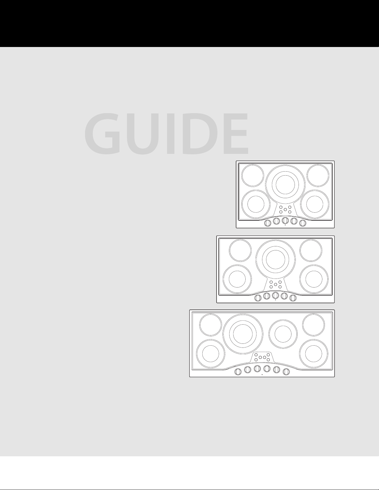
3 Series
Built-In Electric Cooktop
RVEC330
RVEC336
RVEC345
Installation
Page 2

Table of Contents
Warnings & Important Safety Instructions________________________________________________3
Dimensions _________________________________________________________________________5
Specifications________________________________________________________________________6
Cutout Dimensions ___________________________________________________________________7
Clearance Dimensions (Proximity to Cabinets) ____________________________________________8
Clearance Dimensions (Wood/Composite Overlay) ________________________________________9
Electrical Requirements ______________________________________________________________10
General Information _________________________________________________________________11
Installation_________________________________________________________________________12
Final Preparation____________________________________________________________________13
Performance Checklist _______________________________________________________________13
Service & Registration _______________________________________________________________14
2
Page 3
IMPORTANT
• Before beginning, please read these
instructions completely and carefully.
3
– Please Read and Follow
• DO NOT remove permanently affixed labels,
warnings, or plates from the product. This
may void the warranty.
• Please observe all local and national codes
and ordinances.
• Please ensure that this product is properly
grounded.
• The installer must leave these instructions
with the consumer who should retain for
local inspector’s use and for future
reference.
• Installation must conform with local codes
or, in the absence of codes, the National
Electrical Code, ANSI/NFPA-70 – latest
edition.
In Canada: Electrical installation must be in
accordance with the current CSA C22.1
Canadian Electrical Codes Part 1 and/or local
codes.
Your safety and the safety of others is
very important.
We have provided many important safety
messages in this manual and on your
appliance. Always read and obey all
safety messages.
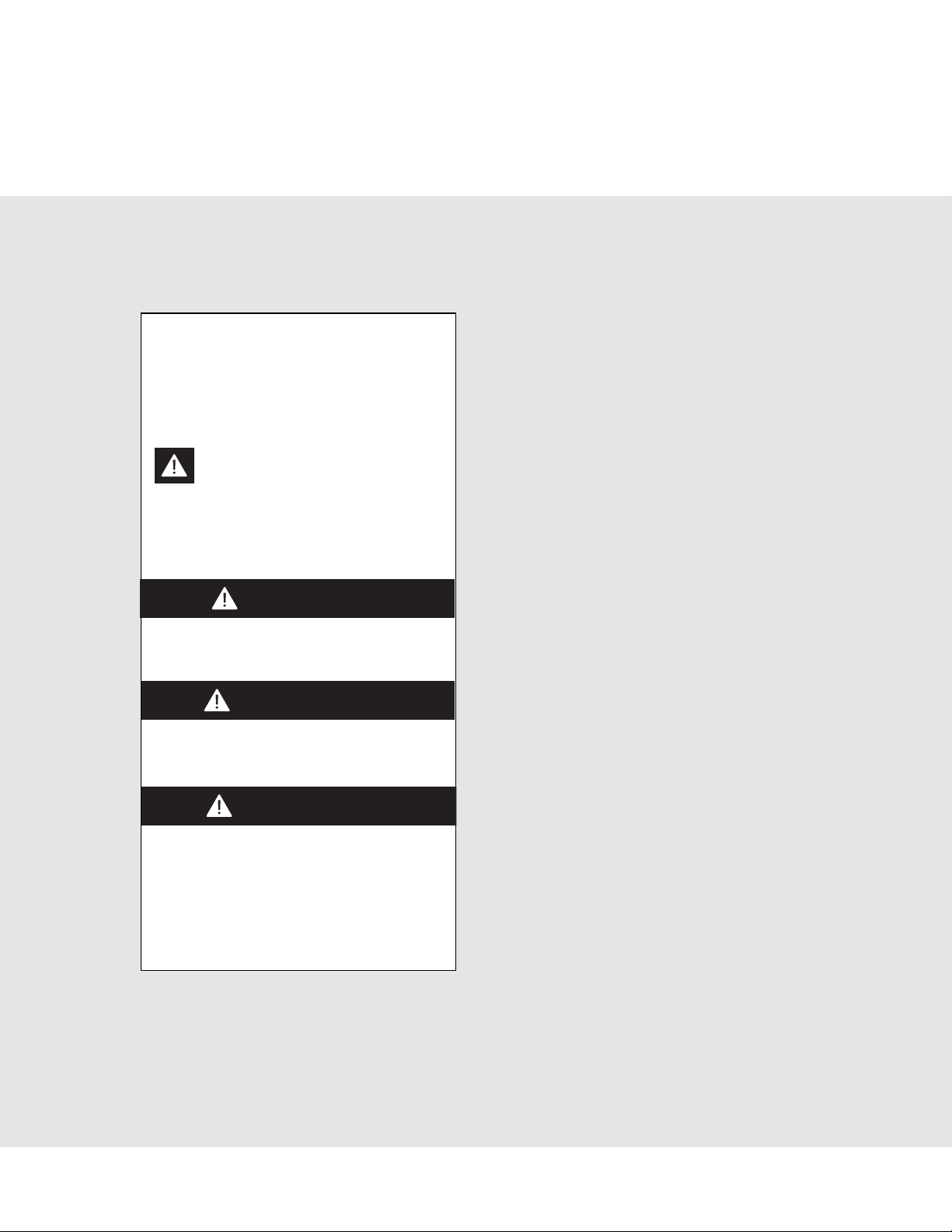
This is the safety alert symbol. This
symbol alerts you to hazards that
can kill or hurt you and others.
All safety messages will be preceded by
the safety alert symbol and the word
“DANGER,” “WARNING” or “CAUTION.”
These words mean:
Hazards or unsafe practices
which WILL result in severe personal
injury or death
DANGER
Hazards or unsafe practices
which COULD result in severe personal
injury or death
Hazards or unsafe practices which
COULD result in minor personal injury
or property damage.
All safety messages will identify the
hazard, tell you how to reduce the chance
of injury, and tell you what can happen if
the instructions are not followed.
WARNING
CAUTION
Page 4
IMPORTANT4– Please Read and Follow
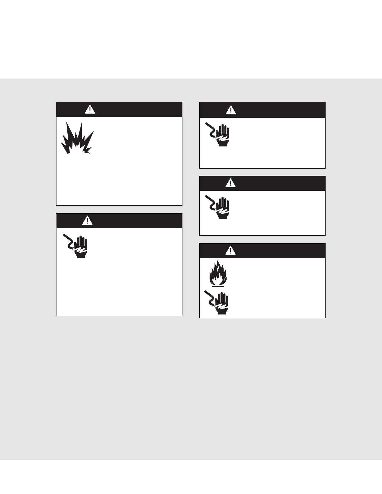
CAUTION
Be sure the electric power is
off from the breaker box to the
junction box until the cooktop
is installed and ready to
operate. The junction box should be
connected to a suitable ground.
WARNING
The electrical power to the
unit must be shut off while line
connections are being made.
Failure to do so could result
in serious injury or death.
WARNING
FIRE AND ELECTRICAL
SHOCK HAZARD
DO NOT use an extension
cord with this appliance. Such
use may result in fire, electrical
shock, or other personal injury.
WARNING
BURN HAZARD
The use of cabinets for
storage above the appliance
may result in potential burn
hazard. Combustible items
may ignite, metallic items may become
hot and cause burns. If a cabinet storage
is to provided the risk can be reduced by
installing a range hood that projects
horizontally a minimum of 5" (12.7 cm)
beyond the bottom of the cabinets.
WARNING
ELECTRICAL
GROUNDING
INSTRUCTIONS
This cooktop must be electrically
grounded in accordance with local codes
or, in the absence of codes, with the
National Electrical Code, ANSI/NFPA-70
– latest edition. FOR PERSONAL
SAFETY, THIS APPLIANCE MUST BE
PROPERLY GROUNDED.
Page 5
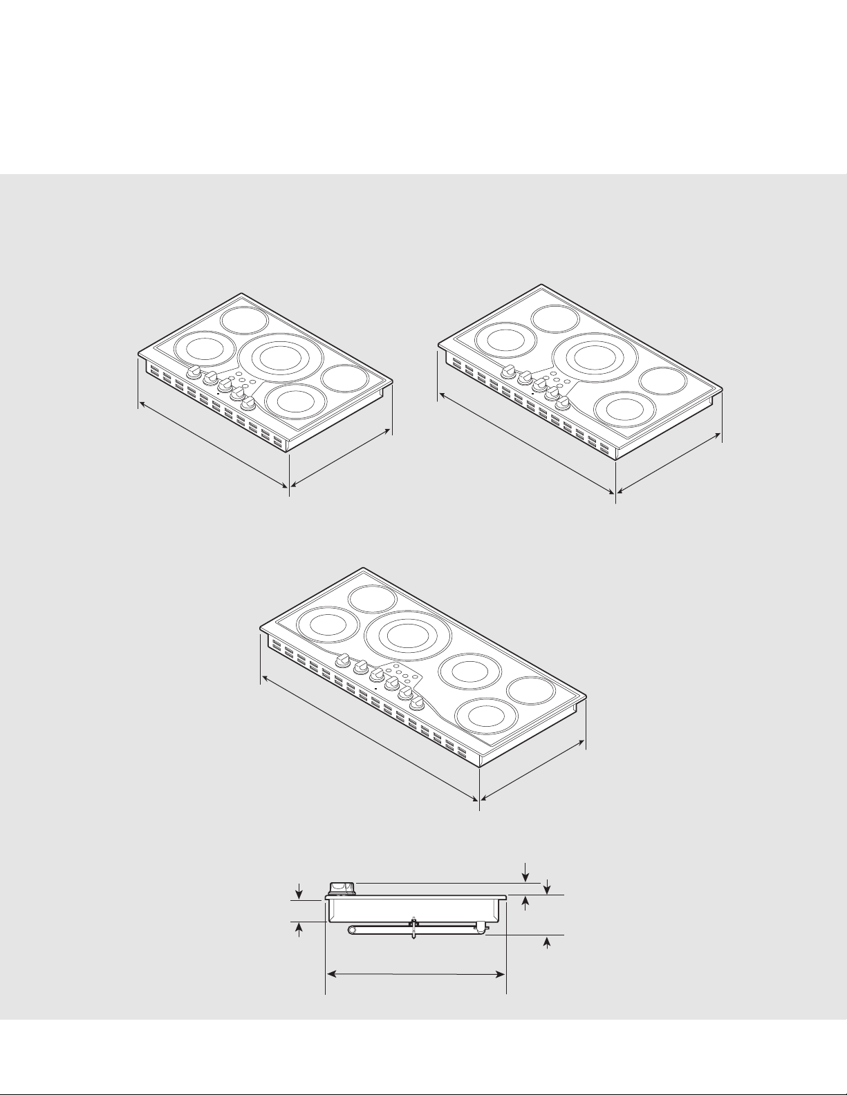
Dimensions
5
30” Electric Cooktop
45” Electric Cooktop
Side view
36” Electric Cooktop
30-3/4”
(78.1 cm)
21”
(53.4 cm)
36-3/4”
(93.3 cm)
21”
(53.4 cm)
3-1/8”
(7.9 cm)
45”
(114.3 cm)
21”
(53.4 cm)
1-5/8”
(4.1 cm)
4-1/2”
(11.4 cm)
21”
(53.4 cm)
Page 6
6
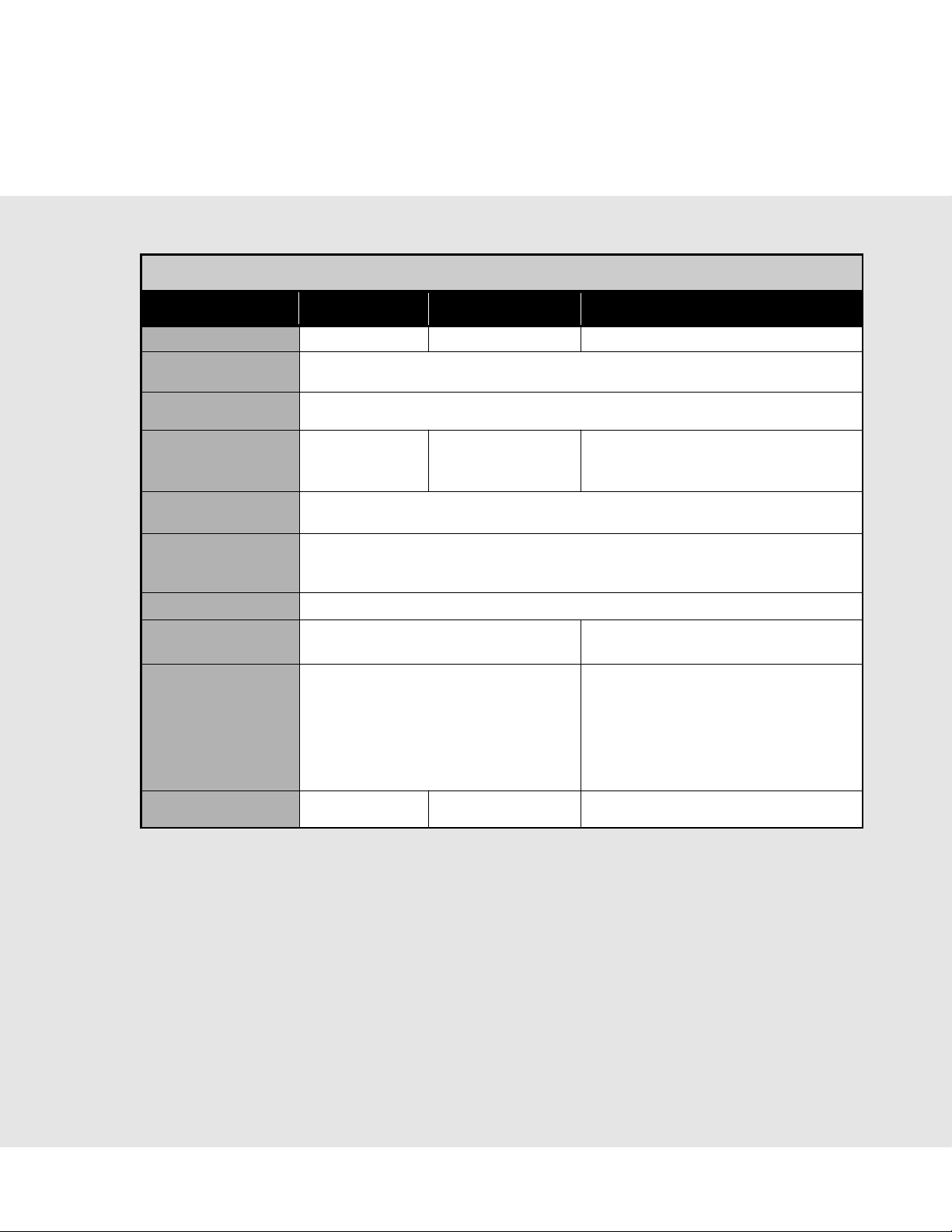
Specifications
Electric Cooktop
Description
30”W 36”W
45”W
Overall width
30-3/4” (78.1 cm) 36-3/4” (93.3 cm) 45” (114.3 cm)
Overall height
from bottom
4-1/2” (11.4 cm)
Overall depth
from rear
21” (53.3 cm)
Cutout width
Minimum
Maximum
28-7/8” (73.3 cm)
29-7/8” (75.9 cm)
34-7/8” (88.5 cm)
35-7/8” (91.1 cm)
43-1/8” (109.5 cm)
44-1/8” (112.1 cm)
Cutout height
with conduit
4-1/8” (10.5 cm)
Cutout depth
Minimum
Maximum
20” (50.8 cm)
20-1/4” (51.4 cm)
Electrical requirements
240/208v 50/60hz
Maximum
amp usage
240V—40.0 amps
208V—34.6 amps
240V—48.4 amps
208V—34.6 amps
Surface element rating
Right front
Right rear
Center triple
Center double
Left front
Left rear
240V 208V
2000/1000 watts 2000/1000 watts
1200 watts 1200 watts
1100/1000/1100 watts 1100/1000/1100 watts
N/A N/A
2000/1000 watts 2000/1000 watts
1200 watts 1200 watts
240V 208V
2000/1000 watts 2000/1000 watts
1200 watts 1200 watts
1100/1000/1100 watts 1100/1000/1100 watts
2000/1000 watts 2000/1000 watts
2000/1000 watts 2000/1000 watts
1200 watts 1200 watts
Approximate
shipping weight
52 lb. (23.6 kg) 60 lb. (27.0 kg) 71 lb. (32.2 kg)
Page 7
7
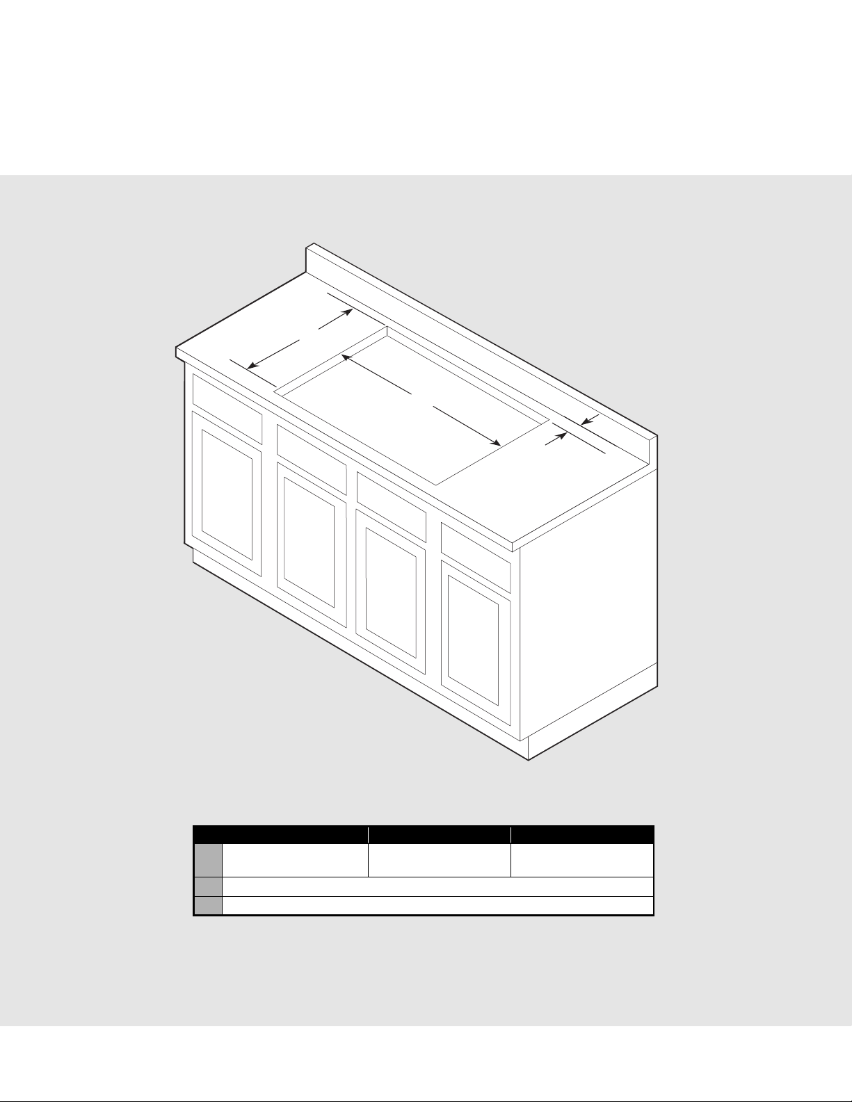
Cutout Dimensions
Note: Based on 24” deep cabinet with 3/4” backsplash.
30” W. 36” W. 45” W.
A 28-7/8” (73.3 cm) min. to
29-7/8” (75.9 cm) max.
34-7/8” (88.5 cm) min. to
35-7/8” (91.1 cm) max.
43-1/8” (109.5 cm) min. to
44-1/8” (112.1 cm) max.
B 20” (50.8 cm) min. to 20-1/4” (51.4 cm) max.
C 1” (2.5 cm) min.
B
A
C
Page 8
8
Clearance Dimensions (Proximity to Cabinets)
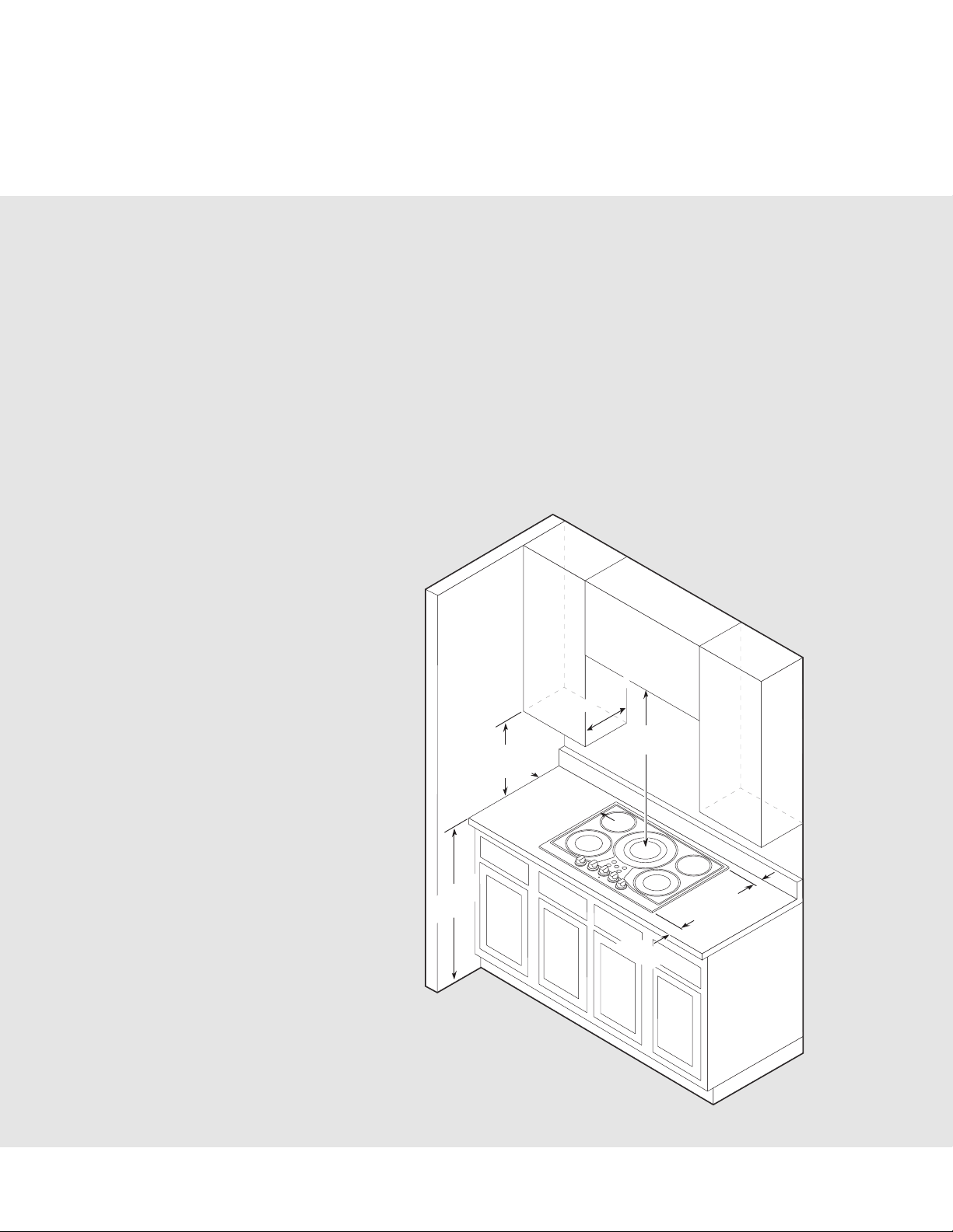
Proximity to Side Cabinet Installation
• The cooktop may be installed directly to
existing base cabinets.
• The cooktop CANNOT be installed directly
adjacent to sidewalls, tall cabinets, tall
appliances, or other side vertical surfaces
above 36” (91.4 cm) high. There must be a
minimum of 6” (15.2 cm) side clearance
from the cooktop to such combustible
surfaces above the
36” (91.4 cm) counter height.
• Within the 6” (15.2 cm) side clearance to
combustible vertical surfaces above
36” (91.4 cm), the maximum wall cabinet
depth must be 13” (33.0 cm) and wall
cabinets within this 6” (15.2 cm) side
clearance must be 18” (45.7 cm) above the
36” (91.4 cm) high countertop.
• Wall cabinet above the cooktop
must be a minimum of 36”
(91.4 cm) above the countertop
for a full width of the cooktop.
The minimum height requirement
does NOT apply if a rangehood is installed
over the cooking surface.
Minimum Clearances from Adjacent
Combustible Construction
• Above countertop 36” (91.4 cm) minimum
• Side 6” (15.2 cm)
• Rear 0” (0.0 cm)
• Within 6” side clearance. Wall cabinets no
deeper than 13” (33.0 cm)
• Must be minimum 18” (45.7 cm) above
countertop
• Wall cabinets directly above the product
must be minimum 36” (91.4 cm) above the
countertop
13” max.
33.0 cm)
18” min.
(45.7 cm)
6” min.
(15.2 cm)**
(
36” min.
(91.4 cm)*
Dimensions show
n are for use
with combustible surfaces unless
otherwise stated.
*Note: 36” minimum unless using a hood.
36” min.
91.4 cm)
(
0” min.
(0.0 cm)
3-1/8”
(7.9 cm)
min.
Page 9
9
Wall Installation
Island Installation
Clearance Dimensions (Wood/Composite Overlay)
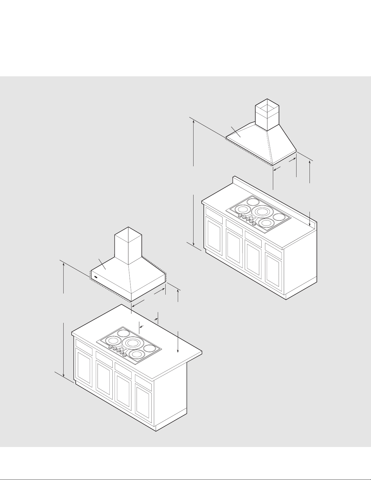
The bottom of a standard hood should be 30”
(76.2 cm) min. to 36” (91.4 cm) max. above the
countertop. This would typically result in the
bottom of the hood being
66” (167.6 cm) to 72” (182.9 cm) above the
floor. Refer to the rangehood installation
instructions for additional information. These
dimensions provide for safe and efficient
operation of the hood.
Wood/Composite
Overlay
66”min.
(167.6 cm)
to
72”max.
(182.9 cm)
Wood/Composite
Overlay
24”
(61.0 cm)
30”min.
(76.2 cm)
to
36”max.
(91.4 cm)
66”min.
(167.6 cm)
to
72”max.
(182.9 cm)
30”
(76.2 cm)
6”
(15.2 cm)
30”min.
(76.2 cm)
to
36”max.
(91.4 cm)
Page 10
10
Electrical Requirements
Electrical Requirements
Check your local codes regarding this unit.
This cooktop is supplied with a 3-wire, A.C.
208Y/120 volt or 120/240 volt, 60 HZ electrical
system. A white (neutral) is not needed for this
unit. See next section for grounding
instructions. It should be fused separately.
Refer to the specifications chart and the
identification label on the bottom of the
burner box for kilowatt rating and
recommended amperage. House wiring and
fusing must comply with local codes. If no
local codes are applicable, wire in accordance
with the National Electrical Code, ANSI/NFPA70 – latest edition.
Electrical Connection
When making the wire connections, use
the entire length of the conduit provided
(3 feet). The conduit must not be cut. Connect
the red and black leads from the unit conduit
to the corresponding leads in the junction box.
The bare ground wire in the conduit is
connected to the unit frame. When connecting
to a 3-conductor branch circuit, if local codes
permit, connect the bare ground connector
lead of the unit to the branch circuit neutral
(gray or white in color).
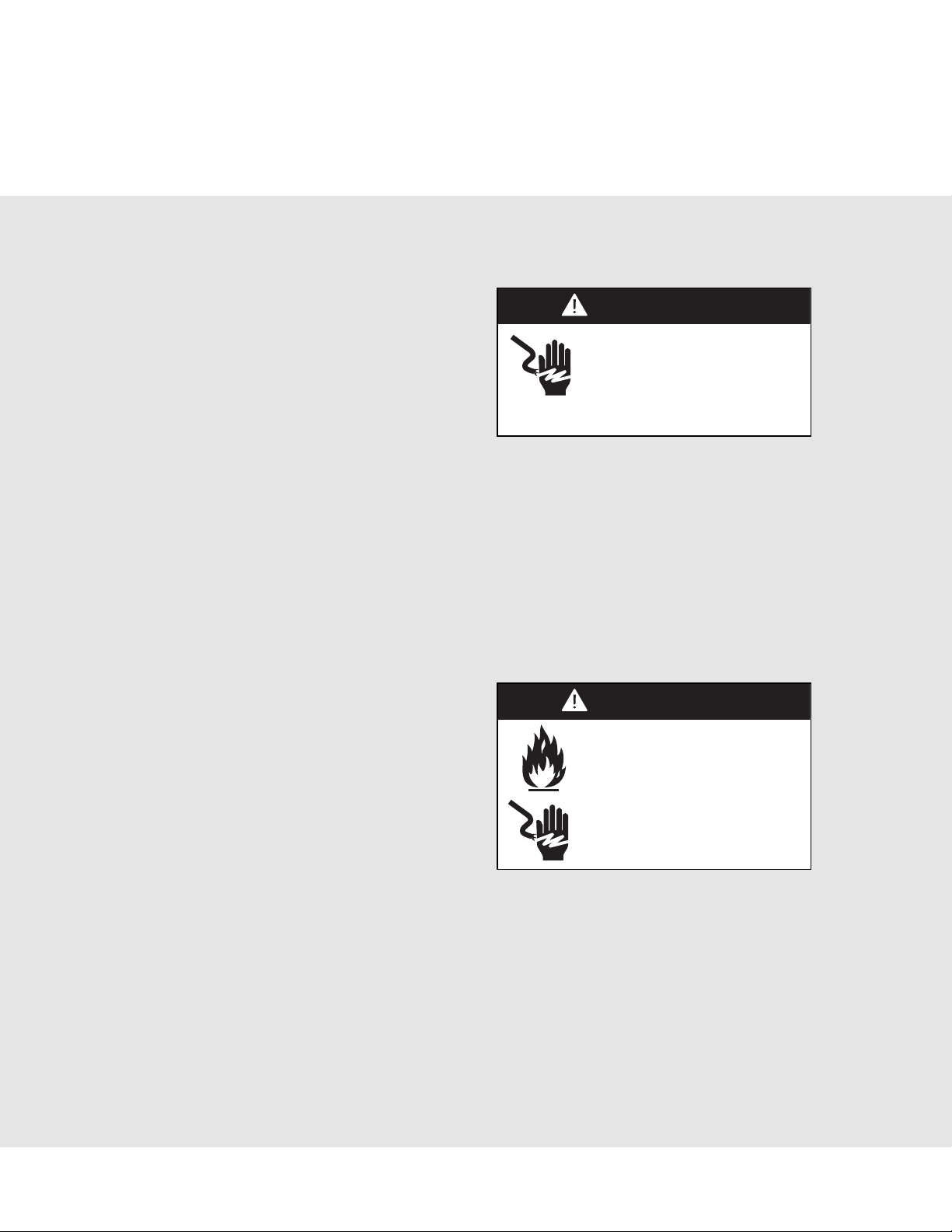
WARNING
The electrical power to the
unit must be shut off while line
connections are being made.
Failure to do so could result
in serious injury or death.
WARNING
FIRE AND ELECTRICAL
SHOCK HAZARD
DO NOT use an extension
cord with this appliance. Such
use may result in fire, electrical
shock, or other personal injury.
Page 11
11
General Information
READ AND FOLLOW ALL WARNING AND
CAUTION INFORMATION WHEN
INSTALLING THIS APPLIANCE.
• All openings in the wall behind the appliance
in the floor under the appliance shall be
sealed
• Keep appliance area clear and free from
combustible materials, gasoline and other
flammable vapors.
• Disconnect the electrical supply prior to
servicing or cleaning.
• When removing the cooktop for service
and/or cleaning, disconnect AC power
supply.
• Electrical requirements are listed in the
product specifications under the “Electrical
Requirements” section.
This appliance shall not be used for
space heating. This information is based
on safety considerations.
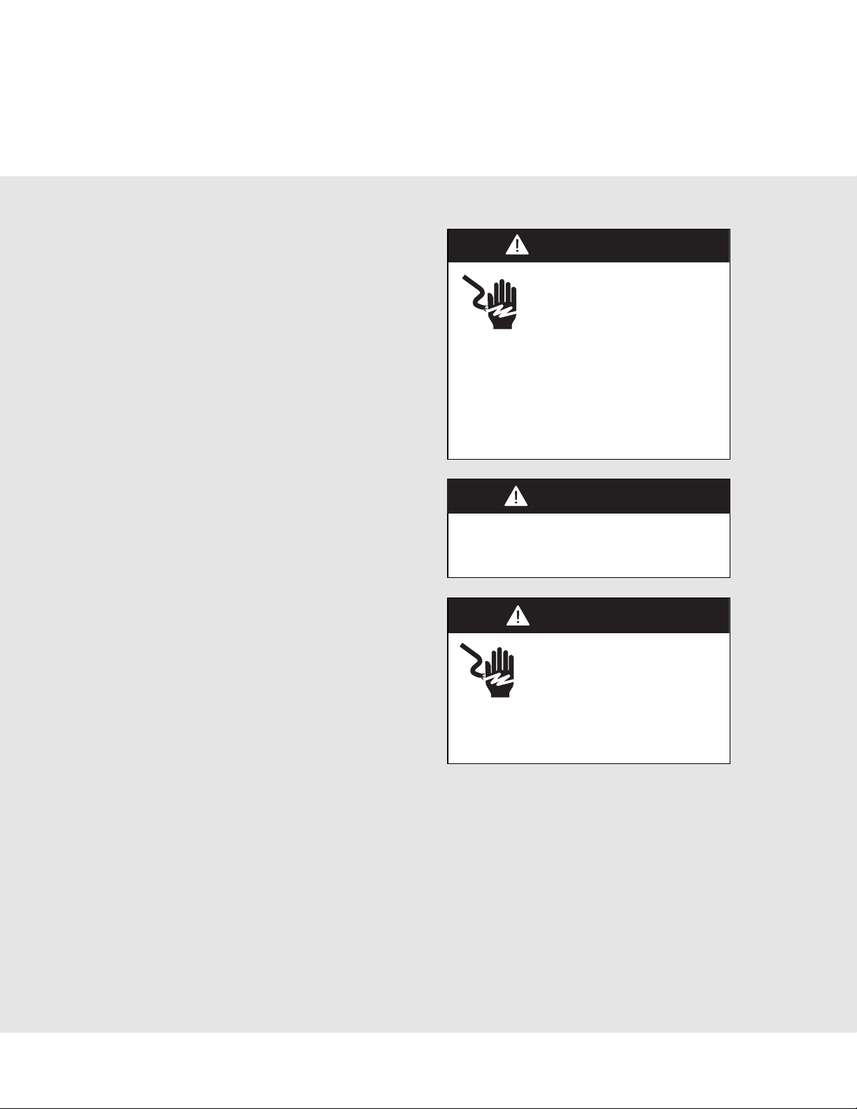
WARNING
WARNING
ELECTRICAL
GROUNDING
INSTRUCTIONS
This cooktop must be electrically
grounded in accordance with local codes
or, in the absence of codes, with the
National Electrical Code, ANSI/NFPA-70
– latest edition. FOR PERSONAL
SAFETY, THIS APPLIANCE MUST BE
PROPERLY GROUNDED.
CAUTION
Be sure the electric power is
off from the breaker box to the
junction box until the cooktop
is installed and ready to
operate. The junction box should be
connected to a suitable ground.
DO NOT use aGFI circuit.
Page 12
Installation
12
1
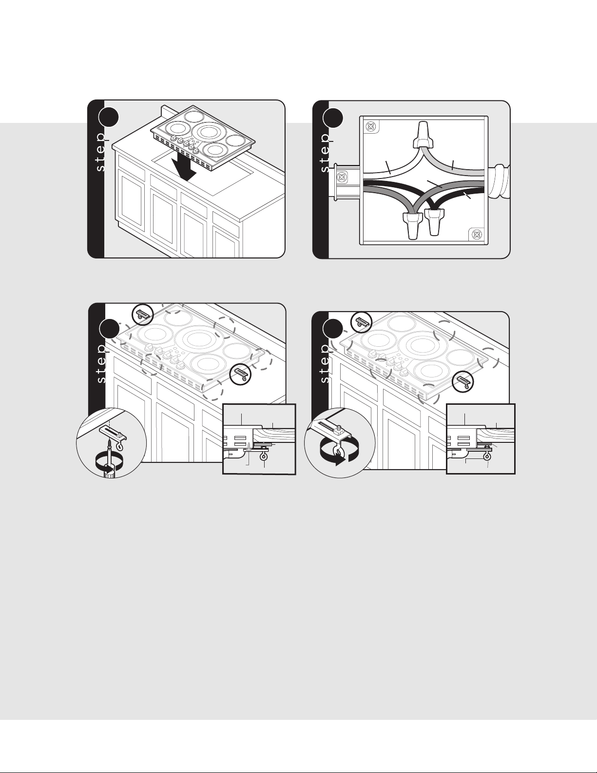
Lower cooktop into cutout.
Connect the red and black leads from the unit
conduit to the corresponding leads in the junction
box.
Cooktop
Bracket
Countertop
Screw
Filler
Block
3
Cooktop
Bracket
Eye Bolt
Countertop
Filler
Block
4
Screw hold down brackets to the burner box using
the #10 x 1/2” sheet metal screws. There are 6
bracket assemblies included. There must be a
minimum of 2 brackets installed with the possibility
of up to 6 in locations noted depending on
installation
Screw sheet metal screws into brackets
and tighten firmly against bottom of countertop.
Note: It is recommended to use a filler block
between the bolt and the underside of the
countertop to prevent any damage to the
countertop. Failure to do so may result in cracking
or splitting of the countertop.
2
Neutral
Red
Green
Black
Page 13

13
Final Preparation
• Some stainless steel parts may have a
plastic protective wrap which must be
peeled off.
• All stainless steel body parts should be
wiped with hot, soapy water and with a
liquid cleaner designed for this material.
If buildup occurs, DO NOT use steel wool,
abrasive cloths, cleaners, or powders!
Performance Checklist
A qualified installer should carry out the
following checks:
Check top surface elements
1. Check top surface elements – glow red
when turned on.
2. Check hot surface indicator lights – glow
red when corresponding element is hot.
If it is necessary to scrape stainless steel to
remove encrusted materials, soak with hot,
wet cloths to loosen the material, then use a
wood or nylon scraper.
DO NOT use a metal knife, spatula, or any
other metal tool to scrape stainless steel!
Scratches are almost impossible
to remove.
Any adjustments necessary that are a result of
the installer not following instructions will be the
responsibility of the installer, dealer of the end
user of this product.
Page 14

14
Service & Registration
Only authorized replacement parts may be used in performing service on the appliance.
All servicing should be referred to a qualified technician.
Contact Viking Range at 1-888-845-4641 for the nearest service parts distributor in your area or
write to:
VIKING RANGE, LLC
PREFERRED SERVICE
111 Front Street
Greenwood, Mississippi 38930 USA
The serial number and model number for your appliance can be found by looking under the
cooktop.
Record the following information indicated below. You will need it if service is ever required.
Model number ____________________________________________________________________________________
Serial number _____________________________________________________________________________________
Date of purchase __________________________________________________________________________________
Date installed ______________________________________________________________________________________
Dealer's name _____________________________________________________________________________________
Address ___________________________________________________________________________________________
These installation instructions should remain with the unit
for future reference.
Page 15

15
Page 16

F21213E EN
(061519)
Viking Range, LLC
111 Front Street
Greenwood, Mississippi 38930 USA
(662) 455-1200
For product information, call 1-888-845-4641
or our website at vikingrange.com
 Loading...