

Viking RVDR33025BCYLP, RVGR33025BAB Installation manual

1-EN
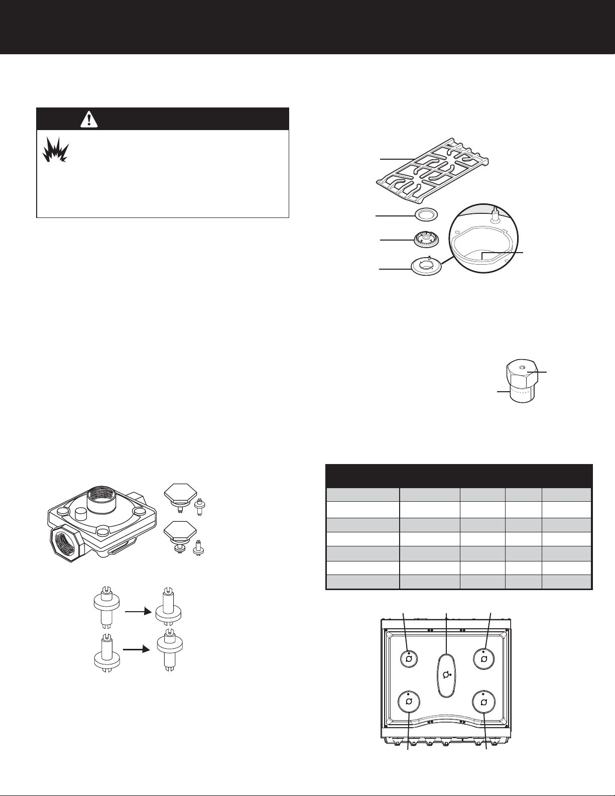
The pressure regulator and the burner orifices are set for Natural
gas. To use Liquid Propane gas, the regulator and burner orifices
must be converted.
To convert the range to LP gas, follow these instructions:
1. Disconnect all electrical power at the main circuit breaker or
fuse box.
2. Shut off the gas supply to the range by closing the manual
shut-off valve.
Converting the Pressure Regulator
1. Locate the pressure regulator which can be found on the back
of the range on the right hand side if facing the back of the
range.
2. Unscrew the hex nut cap from the top of the regulator.
3. Unsnap the plastic plunger from the hex nut.
4. Reverse the plunger and reinstall onto the hex nut by
pressing firmly.
Note: Plunger is marked “Nat” and “LP”. Converted fuel type will
be shown on the lower portion of the plunger.
Converting the Surface Burners
1. Remove the top grates, burner caps, and burner heads.
2. Using a 9/32” or 7 mm nut driver remove the top burner
orifices. These may be accessed through the opening in the
burner base.
Note: Save these orifices for future conversion back to Natural gas,
if required.
3. Locate the proper LP surface
burner orifices included with
the kit according to the chart
below. The orifice stamp can
be either the metric diameter
size or the orfice drill size.
4. Install the orifices in their correct location. To prevent leakage,
make sure the orifice spuds are securely screwed into the
burner base.
WARNING
The conversion must be performed by a qualified
installer or gas supplier in accordance with the
manufacturer’s instructions and all codes and
requirements of the authority having jurisdiction. Failure to
follow ALL instructions could result in serious injury or
property damage. The qualified agency performing this
work assumes responsibility for this conversion.
RLPKR2 LP Conversion Kit Instructions for RVGR3302/RVDR3302 Ranges
Part Number
Burner BTU Rate
DiametermmOrifice
Stamp
057741-901
Left front (A)
16,000
1.19
119
057741-902
Left rear (B)
6,500 0.71
057741-903
Center (C) 8,000
057741-905
Right rear (D) 11,000 0.95
057741-904
Right front (E) 15,000 1.15
115
035282-000
Bake 30,000 1.68
1.68
035283-000
Broil 14,500 1.03
1.03
Burner
grate
Burner
cap
Burner
head
0.79
Orifice
spud
Orifice
stamp
Burner
base
Orifice
NAT
LP
Apply sideways finger pressure
to remove pin from cap.
conversion
LP
NAT
conversion
LP
NAT
B
A
CD
0.85
E
71
85
95

2-EN
Converting the Bake Burner
Important: The orifice tip must be located 3/16” inside the burner
for proper gas mixture and combustion. The depth of the orifice
can be adjusted by turning the orifice counterclockwise (more
depth) or clockwise (less depth). Reverse procedure as needed to
reassemble.
Converting the Broil Burner
1. Remove the screws (4) from the broiler baffle.
2. Carefully remove the broiler burner
Note: Pay close attention to the igniter wire while removing the
broiler burner.
the igniter wire.
6. Reposition the broiler burner in its original position.
7. Replace the four screws into the broiler baffle.
Air Shutter Settings for Broiler Burner
1. Use a screwdriver to loosen the air shutter screw.
2. Adjust the air shutters for LP gas by rotating the shutter to the
fully open position. Your final settings may vary.
3. Retighten the air shutter screw.
Bake and broiler flame must be checked with the door closed to
properly check flame characteristics.
4. Turn on the gas.
5. Turn on the electricity.
6. Retighten the air shutter screw.
7. Turn on the bake and broiler burner.
8. As you watch the flame with the oven door closed, check the
following through the oven door window:
a. If the flames are yellow, open the air shutter more.
b. If the flames blow away or flutter from the burner, close
the air shutter more.
9. Open the oven door and check the inner cone of the bake
and broiler burner flame. It should be approximately 1/2” to
3/4” long for the bake and broil burners. The combustion
quality of the burner flames needs to be determined visually.
With LP gas, some yellow tipping on the outer cones is
normal.
10. When all adjustments are made and the results are
satisfactory then replace the oven bottom cover.
In some cases, foreign particles in the gas line may cause an
orange flame at first but this will soon disappear.
Note: To convert the oven back to Natural gas, reverse the
instructions given for making the LP gas adjustments.
Note: When the LP/Propane conversion is finished, complete the
enclosed conversion label and place it next to the rating label.
Vo let d 'ai
Air Shutter
Air Shutter
Set Screw
Orifice
Hood
Ad justment
Sc
rew
Air Shutter
Adjustment screw
Air shutter
WARNING
If you attempt to measure the inner cone of the
flame, please use caution as burns could result.
1. Remove oven racks and oven support.
2. Remove oven bottom.
3. Remove screws securing bake igniter to bake burner.
4. Remove screws securing bake burner shield to oven burner box.
5. Remove screws securing bake burner to oven burner box.
6. Loosen air shutter screw and adjust opening on burner to 3/8”
and tighten air shutter screw.
7. Remove orifice by turning counterclockwise and replace with
orifice 1.68 from bag labeled.
3. Disconnect the igniter wire.
4. Use a 1/2” wrench to remove the broiler burner natural gas
orifice hood and replace with LP broiler burner hood 1.03.
5. Reinstall the converted broiler burner by first firmly attaching
3-EN
The pressure regulator and the burner orifices are set for LP gas.
To use natural gas, the regulator and burner orifices must be
converted.
To convert the range to NAT gas, follow these instructions:
1. Disconnect all electrical power at the main circuit breaker or
fuse box.
2. Shut off the gas supply to the range by closing the manual
shut-off valve.
Converting the Pressure Regulator
1. Locate the pressure regulator which can be found on the back
of the range on the right hand side if facing the back of the
range.
2. Unscrew the hex nut cap from the top of the regulator.
3. Unsnap the plastic plunger from the hex nut.
4. Reverse the plunger and reinstall onto the hex nut by
pressing firmly.
Note: Plunger is marked “Nat” and “LP”. Converted fuel type will
be shown on the lower portion of the plunger.
Converting the Surface Burners
1. Remove the top grates, burner caps, and burner heads.
2. Using a 9/32” or 7 mm nut driver remove the top burner
orifices. These may be accessed through the opening in the
burner base.
Note: Save these orifices for future conversion back to NAT gas, if
required.
3. Locate the proper NAT surface
burner orifices included with
the kit according to the
diagram below. The orifice
stamp can be either the metric
diameter size or the orfice drill size.
4. Install the orifices in their correct location. To prevent leakage,
make sure the orifice spuds are securely screwed into the
burner base.
WARNING
The conversion must be performed by a qualified
installer or gas supplier in accordance with the
manufacturer’s instructions and all codes and
requirements of the authority having jurisdiction. Failure to
follow ALL instructions could result in serious injury or
property damage. The qualified agency performing this
work assumes responsibility for this conversion.
RNKR2 NAT Conversion Kit Instructions for RVGR3302/RVDR3302 Ranges
B
A
E
CD
Part Number
Burner BTU Rate
DiametermmOrifice
Stamp
057747-901
Left front (A)
18,000
2.00
200
057747-902
Left rear (B)
9,100 1.38
138
057747-903
Center (C) 9,100 1.38
138
057747-905
Right rear (D) 12,000 1.58
158
057747-904
Right front (E) 17,000 1.88
189
015695-000
Bake 30,000 2.58 #38
PB040034
Broil 15,000 1.87 #50
NAT
LP
Apply sideways finger pressure
to remove pin from cap.
Burner
grate
Burner
cap
Burner
head
Burner
base
Orifice
Orifice
spud
0.79
Orifice
stamp
conversion
LP
NAT
LP
conversion
NAT
 Loading...