

Page 1
RC-2A
RC-2A
Remote Touch
Tone Controller
April 18, 2001
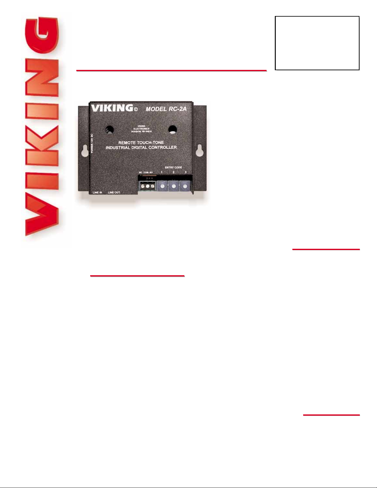
The RC-2A Remote Controller provides
remote relay operation from any standard
Touch Tone telephone.
The controller is designed to be installed
either locally or remotely. For local installations the RC-2A can be installed in series
on any analog communications path, such
as analog C.O. lines, analog PABX/KSU
stations or Viking’s W-Series Doorboxes.
and will passively monitor for Touch Tone
commands.
For off-premise applications, the RC-2A will
Control Relay Contacts Remotely
PPhhoonnee......771155..338866..8888661
1
hhttttpp::////wwwwww..vviikkiinnggeelleeccttrroonniiccss..ccoom
m
• Programmable access code
• Normally open or normally closed relay
• Selectable relay closure times
• Selectable ring delay (1, 2, 6, or 15)
• Easy installation with modular jacks and
screw terminals
• Automatic disconnect or return to secure
mode after 60 seconds
• One year warranty
Power: 120VAC / 12VDC 500mA UL listed adapter provided
Dimensions: 133mm x 89mm x 44mm (5.25” x 3.5” x 1.75”)
Shipping Weight: .9 kg (2 lbs)
Environmental: 0° C to 32° C (32° F to 90° F) with 5% to 95%
non-condensing humidity
Relay Contact Ratings: .5A @ 125V AC/1A @ 30V DC
Connections: (2) RJ-11 jacks and 3 pin screw terminal block
PPrraaccttiicce
e
T
T
EELLEECCOOM
M
S
S
OOLLUUTTIIOONNSSFFOORRTTHHE
E
221
1
SST
T
C
C
EENNTTUURRY
Y
TECHNICAL
TECHNICAL
FFeeaattuurrees
s
SSppeecciiffiiccaattiioonns
s
answer analog C.O. lines or PABX/KSU stations after a selectable ring delay. A field
programmable access code can also be programmed to prevent unauthorized usage.
The RC-2A will then allow remote relay operation.
Remote Control of:
• High security building entry
• Heating/cooling equipment
• Pumps and fans
• Security systems
• Gates
• Lighting
• PABX/KSU reset
AApppplliiccaattiioonns
s
iinnffoo@@vviikkiinnggeelleeccttrroonniiccss..ccoom
m
MMaaddeeiinntthheeUU..SS..AA.
.
Page 2
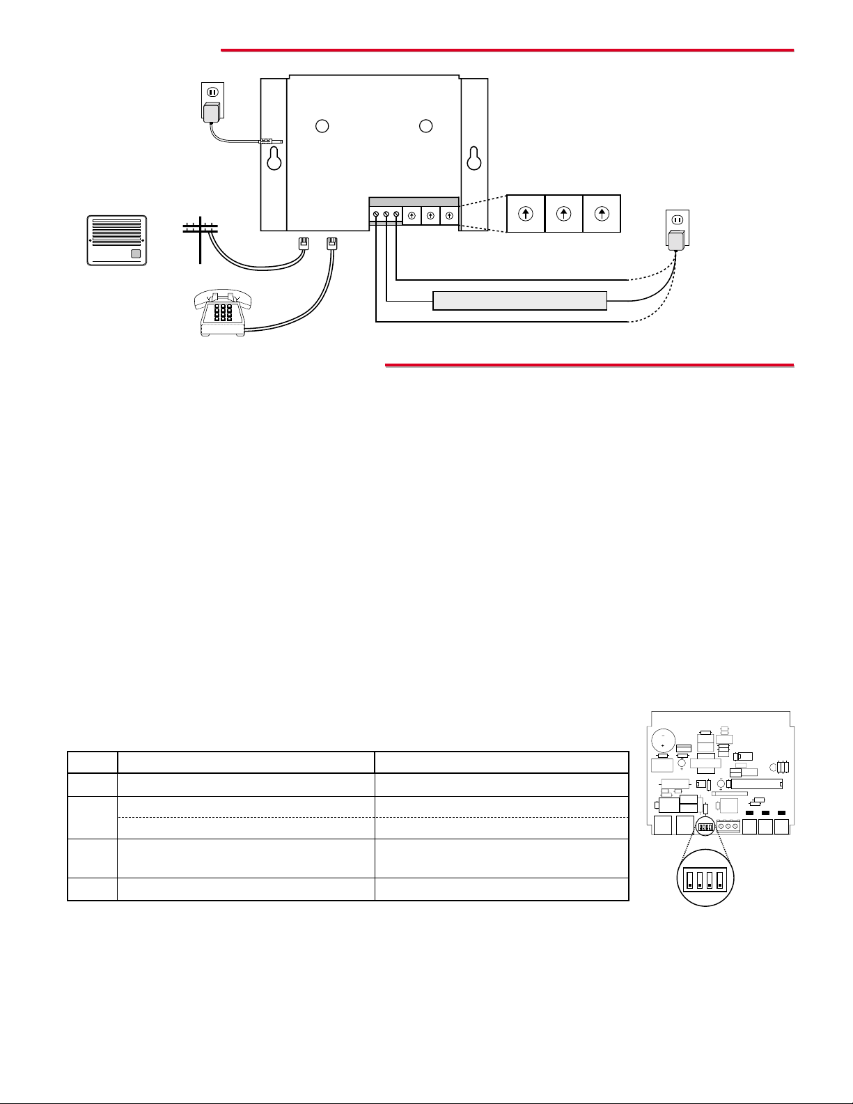
IInnssttaallllaattiioon
n
A. Security Access Code
Note: An access code should be used, when the RC-2A is used on a line with other equipment that may dial.
1. Setting the Access Code
The RC-2A contains (3) rotary access code switches (see diagram above). Using a small flat blade screwdriver,
rotate the white arrow on each switch to the desired access code setting. The code may be any digit 0-9 or “C” (#
on a Touch Tone pad). Note: For extreme security applications, a special telephone with a 4 x 4 keypad may be
used (Fax Back Document 855).
2. Disabling the Access Code
If any rotary access code switch is set to position “D” the access code is disabled. In this case, any call to the
RC-2A will have immediate access to activation codes (see section D). Note: When the access code is disabled,
the setting of DIP switch 3 has no effect (unlimited closures allowed).
LLeeggaaccyyPPrrooggrraammmmiinng
g
B. DIP Switch Settings
DIP switches 1-3 may be used to change the operation of the RC-2A (see chart below).
Switch
1
2
3
4
OFF
Latch commands (10 & 19) are enabled
Ring delay of 15 (no rotary switches set to C)
Ring delay of 2 (any rotary switch set to C)
Unlimited number of closures during access
time
(for future use)
ON
Latch commands are disabled
Ring delay of 6 (no rotary switches set to C)
Ring delay of 1 (any rotary switch set to C)
One closure per correct access code during
access time (no rotary switches set to D)
(for future use)
VIKING
©
MODEL RC-2A
VIKING
ELECTRONICS
HUDSON, WI 54016
REMOTE TOUCH-TONE
INDUSTRIAL DIGITAL CONTROLLER
POWER 12V DC
12V DC
Adapter
included
120V AC
NC COM NO
ENTRY CODE
1 2 3
LINE IN LINE OUT
0
1
2
3
4
5
6
7
8
9
A
B
C
D
E
F
0
1
2
3
4
5
6
7
8
9
A
B
C
D
E
F
0
1
2
3
4
5
6
7
8
9
A
B
C
D
E
F
0
1
2
3
4
5
6
7
8
9
A
B
C
D
E
F
0
1
2
3
4
5
6
7
8
9
A
B
C
D
E
F
0
1
2
3
4
5
6
7
8
9
A
B
C
D
E
F
C.O. Line
or Analog
PABX/KSU
Station
Phone(s)
Normally Open Relay Contact
Normally Closed Relay Contact
Rotary Access
Code Switches
Doorstrike/Magnetic Lock
Call
VIKING©
W-1000, W -2000A
or W-3000
- or -
.5A @ 125V AC
or 1A @ 30V AC
maximum
Gate controllers
do not typically
require power.
JP1
JP2 JP3
1 2 3 4
1 2 3 4
Switch 1: Latch Commands
If this DIP switch is in the ON position, the relay will not be able to be latched (maintained) and command codes 10
and 19 will be ignored.
Switch 2: Ring Delay
The RC-2A answers on the fifteenth ring by default. This can be changed to the first, second or sixth ring by
following the instructions above.
Switch 3: Closure Limitations
If this DIP switch is placed in the ON position, only one closure will be allowed during the access.
Important: The RC-2A ships by default in the Legacy Programming mode. Optional programming is also available (see
Alternative Programming). The alternative programming mode dramatically changes the programming and operation of
the RC-2A. Use only the programming features described in the respective sections for the programming mode you
choose.
Page 3

B. Entry Code Switches
The blue access code switches set the relay activation code. This code can make use of any
of the digits available on the rotary switches, as long as the user is aware that D and E can
only be entered using a special 4x4 keypad. Note: For more information on using the RC-
2A with a special 4x4 keypad, retrieve Fax Back Document 855.
A. Security
D. Relay Activation Codes
To energize relay (two beeps) ...........................................................................................................................
To de-energize relay (one beep) ........................................................................................................................
To energize relay momentarily (.5 seconds) (one beep).....................................................................................
To energize relay while 4 is pressed and for 1 second after (one beep) .............................................................
To energize relay as long as 5 is pressed (.5 seconds minimum) (one beep).....................................................
To energize relay while 6 is pressed, and 5 seconds after (one beep)................................................................
To interrogate the relay status (two beeps - energized, one beep - de-energized) ............................................
To release the phone line (remote only) (three beeps).......................................................................................
Enter
10
19
13
14
15
16
1#
18 or 8
1. Single Digit Relay Activation Code
To program a single digit relay activation code, set any two of the three code
switches to F. Example: FF3 (shown right).
2. Two-Digit Relay Activation Code
To program a two-digit relay activation code, set any of the code switches
to F. The other two switch settings comprise the relay activation code.
Example: F47 (shown right).
3. Special Character Relay Activation Code
To program the relay activation code to be ✱ or #, set all three code switch-
es to F (shown right). In this case, either a ✱ or # will activate the relay.
4. Ring Delay
To program the ring delay to 2 instead of the normal 15, set at least one of
the code switches to B or C (shown right). Example: FFB = “✱” as the
activation code and 2 as the ring delay.
8
9
A
B
C
D
E
F
0
1
2
3
4
5
6
7
8
9
A
B
C
D
E
F
0
1
2
3
4
5
6
7
8
9
A
B
C
D
E
F
0
1
2
3
4
5
6
7
8
9
A
B
C
D
E
F
0
1
2
3
4
5
6
7
8
9
A
B
C
D
E
F
0
1
2
3
4
5
6
7
8
9
A
B
C
D
E
F
0
1
2
3
4
5
6
7
Rotary
Switch
F
C
B
0...9
Touch
Tone
Ignore
#
✱
0...9
Important: With jumper JP1 removed (shown right), programming and
operation are changed dramatically. Please use the following programming sections when JP1 is removed. All Legacy Programming and
Operation become un-usable and you may ONLY program and operate
the RC-2A using the information provided in this section.
AAlltteerrnnaattiivveePPrrooggrraammmmiinng
g
C. JP2 and JP3 Shunt Settings
1. Acknowledgement Tones
To prevent the RC-2A from producing acknowledgement tones,
remove JP2 (shown right).
2. Answering (Ring Trip)
To prevent the RC-2A from answering the phone line, remove JP3
(shown right).
JP1
JP2 JP3
1 2 3 4
JP3
JP2
Internal View
of RC-2A
JP1
JP2 JP3
1 2 3 4
JP1
Internal View
of RC-2A
These activation codes are pre-programmed and cannot be changed except when using the
Alternative Programming mode.
8
9
A
B
C
D
E
F
0
1
2
3
4
5
6
7
8
9
A
B
C
D
E
F
0
1
2
3
4
5
6
7
8
9
A
B
C
D
E
F
0
1
2
3
4
5
6
7
8
9
A
B
C
D
E
F
0
1
2
3
4
5
6
7
8
9
A
B
C
D
E
F
0
1
2
3
4
5
6
7
8
9
A
B
C
D
E
F
0
1
2
3
4
5
6
7
With JP1 removed, access to the RC-2A is immediate and it becomes possible to program a
one, two or three digit relay activation code. No access code is programmable or required to
gain access.
Page 4

JP1
JP2 JP3
1 2 3 4
JP3
JP2
Due to the dynamic nature of the product design, the information contained in this document is subject to change without notice. Viking Electronics, and its affiliates and/or
subsidiaries assume no responsibility for errors and omissions contained in this information. Revisions of this document or new editions of it may be issued to incorporate
such changes.
Fax Back Doc 160 ZF280210 Rev EPrinted in the U.S.A.
PPrroodduuccttSSuuppppoorrttLLiinnee......771155..338866..8866666
6
FFaaxxBBaacckkLLiinnee......771155..338866..4433445
5
C. DIP Switch Settings
The bank of 4 DIP switches provides 16 different contact
closure times according to the following table.
JP1
JP2 JP3
1 2 3 4
1 2 3 4
D. JP2 and JP3 Shunt Settings
1. Acknowledgement Tones
To prevent the RC-2A from producing any acknowledgement
tones remove JP2 (shown right).
2. Answering
To prevent the RC-2A from answering the phone line, remove JP3
(shown right).
Internal View
of RC-2A
A. Accessing the RC-2A Remotely
1. Call the RC-2A using a Touch Tone phone.
2. When the RC-2A answers, a single beep will be heard.
3. If no access code was set, go to step 4. If an access code was set, enter “✱” followed by your access code.
4. Enter a one, two or three digit relay activation code (see Legacy or Alternative Programming section). An
acknowledgement tone should be heard.
5. Enter “8” or “18” before hanging up to force the RC-2A to release the line. Alternatively, the unit will disconnect if
no Touch Tones are detected for 60 seconds.
B. Accessing the RC-2A Locally
1. Establish voice connection with the RC-2A by accessing the doorbox or dedicated line.
2. If no access code was set, go to step 3. If an access code was set, enter “✱” followed by your access code.
3. Enter a one, two or three digit relay activation code (see Legacy or Alternative Programming section). An
acknowledgement tone should be heard.
4. If an access code was set, enter “8” before hanging up to place the RC-2A back into secure mode. Alternatively,
the unit will disconnect if no Touch Tones are detected for 60 seconds.
1
OFF
OFF
OFF
OFF
OFF
OFF
OFF
OFF
ON
ON
ON
ON
ON
ON
ON
ON
2
OFF
OFF
OFF
OFF
ON
ON
ON
ON
OFF
OFF
OFF
OFF
ON
ON
ON
ON
3
OFF
OFF
ON
ON
OFF
OFF
ON
ON
OFF
OFF
ON
ON
OFF
OFF
ON
ON
4
OFF
ON
OFF
ON
OFF
ON
OFF
ON
OFF
ON
OFF
ON
OFF
ON
OFF
ON
Contact Closure Time
1/2 second
1 second
2 seconds
3 seconds
4 seconds
5 seconds
6 seconds
7 seconds
8 seconds
9 seconds
10 seconds
30 seconds
45 seconds
1 minute
5 minutes
10 minutes
OOppeerraattiioon
n
If the RC-2A is programmed to answer a ringing line, it will do so after the selected ring delay. A single acknowledgement
tone will be heard, signaling the user that the RC-2A has answered the line. If a security code has been programmed, it
may be entered at this time and a second confirmation tone will be heard. If the RC-2A is not programmed to answer the
line, it can passively monitor a communication path for the proper access and/or activation code.
The RC-2A provides a contact closure (normally open contacts) remotely via DTMF Touch Tone input over a standard analog C.O. line or P ABX/KSU station. When the correct relay activation code is entered, the RC-2A produces a closure at the
terminal strip followed by a single beep as an acknowledgement tone. If the RC-2A is accessed remotely and there is a
closure already in progress, the RC-2A indicates this by producing two beeps instead of a single beep when it answers. At
this point the user may allow the existing closure to continue or start the closure over again by entering the relay activation
code.
Internal View
of RC-2A
 Loading...