

Viking VMTK306SS, VMTK271SS, PROFESSIONAL VMTK270, PROFESSIONAL SERIES, PROFESSIONAL VMTK271 Installation Instructions Manual
...Page 1
VIKING RANGE CORPORATION
INSTALLATION
Greenwood, Mississippi 38930 USA
111 Front Street
(662) 455-1200
INSTRUCTIONS
PROFESSIONAL SERIES
MICROWAVE BUILT-IN TRIM KIT
Retain for Future Reference
IMPORTANT - PLEASE READ AND FOLLOW
• Before beginning, please read these instructions completely and carefully.
• Be sure to DISCONNECT THE PLUG of the microwave oven from the electrical outlet before installing the built-in trim kit.
Remove the turntable from the oven cavity.
• Because the kit includes metal parts, caution should be used in handling and installation to avoid the possibility of injury.
• Do not remove permanently affixed labels, warnings, or plates from the product. This may void the warranty.
• Please observe all local and national codes and ordinances.
• The installer should leave these instructions with the consumer who should retain for local inspector’s use and for future
reference.
THIS BUILT-IN KIT IS DESIGNED FOR USE ONLY WITH VIKING MICROWAVE OVENS SPECIFYING BUILT-IN KIT
VMTK270/271, VMTK300/301, OR VMTK360/361 ON THE RATING LABEL ON THE LEFT SIDE WALL OF THE OVEN
CAVITY.
IF YOUR LOWER CONVENTIONAL OVEN IS NOT LISTED IN THE USE AND CARE MANUAL OF THE MICROWAVE
OVEN, THEN DO NOT INSTALL THE MICROWAVE OVEN ABOVE IT OR IN ANY AREA WHERE HEAT AND STEAM
ARE GENERATED; FOR EXAMPLE, NEXT TO OR ABOVE A CONVENTIONAL RANGE.
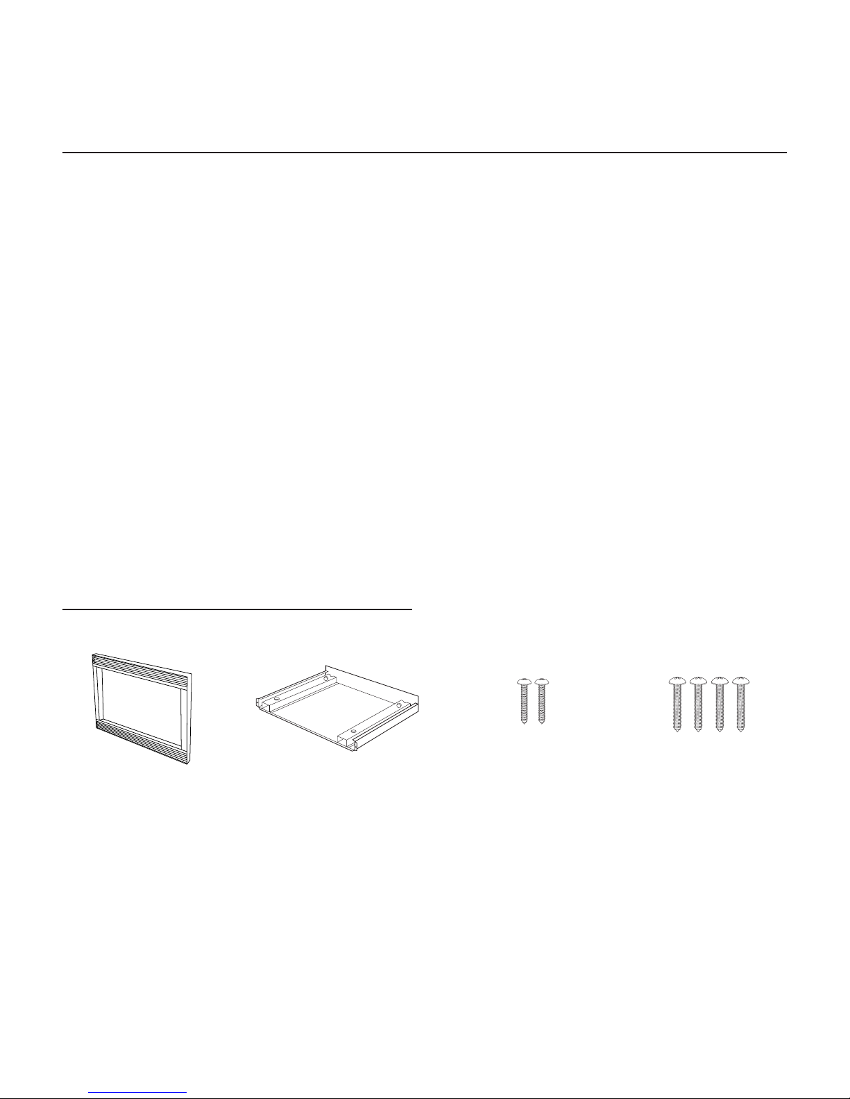
PARTS INCLUDED IN THE VMTK KIT
1) Front Frame Assembly
QTY 1
2) Bottom Duc t Assembly
QTY 1
3) Screw A (1-3/16" length)
QTY 2
4) Screw B (1 3/4" length)
QTY 4
Page 2
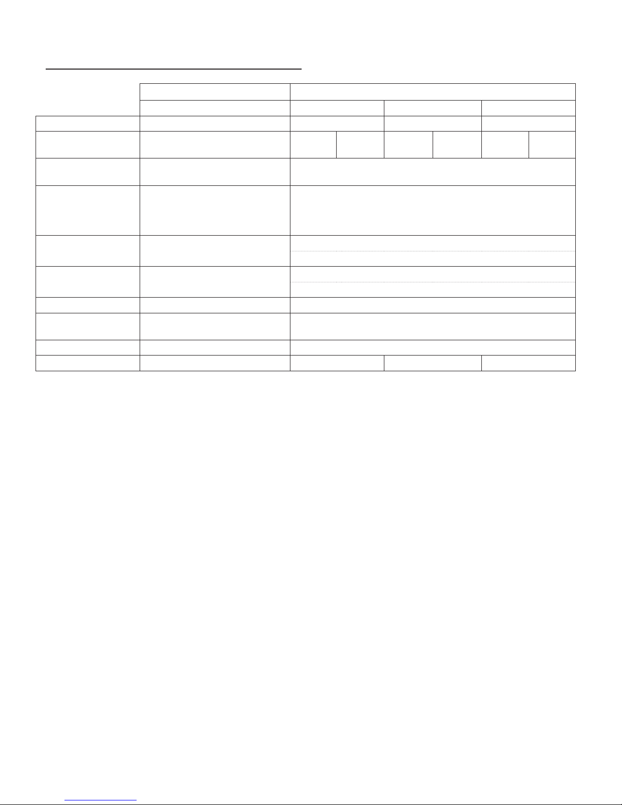
BASIC SPECIFICATIONS
Microwave Oven Built-In Trim Kits
VMOS200 VMTK270/271 VMTK300/301 VMTK360/361
Overall Width 24” (60.9 cm) 26-1/2” (67.3 cm) 29-1/2” (74.9 cm) 35-1/4” (89.5 cm)
Overall Height from
Bottom
Overall Depth from
Rear
Oven Interior Width
Cutout Width N/A Min. 24-3/8” (61.9 cm)
Cutout Height N/A Min. 16-3/4” (42.5 cm)
Cutout Depth N/A Min. 20” (50.8 cm)
Electrical
Requirements
Max. Amp Usage 1.5 KW 13.0 amps N/A
Approx. Shipping Wt. 46 lbs. (20.9 kg) 12.9 lbs. (5.8 kg) 13.9 lbs. (6.3 kg) 14.9 lbs. (6.8 kg)
13-3/8” (33.9 cm) 18-1/4”
(46.3 cm)
19-1/4” (48.9 cm) N/A
17-3/8”
Height
Depth
Overall
120VAC/60 Hz N/A
10-1/2”
18-5/8”
2.0 cu. ft.
(44.1 cm)
(26.6 cm)
(47.3 cm)
17-13/16”
(45.3 cm)
Max. 24-11/16” (62.7 cm)
Max. 17” (43.2 cm)
18-1/4”
(46.3 cm)
N/A
17-13/16”
(45.3 cm)
18-1/4”
(46.3 cm)
17-13/16”
(45.3 cm)
2
Page 3
CABINET OR WALL CUTOUT
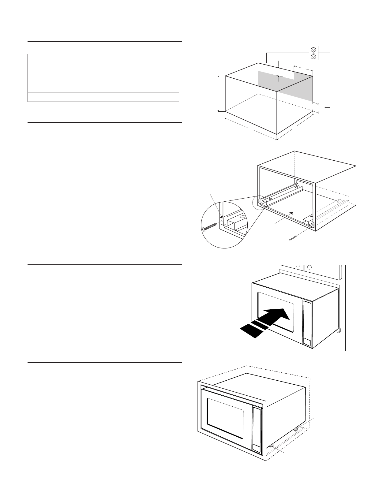
Cutout Dimensions
Illustration 1
Height (A) Minimum 16 3/4" (42.5 cm)
Maximum 17" (43.2 cm)
Width (B) Minimum 24 3/8" (61.9 cm)
Maximum 24 11/16" (62.7 cm)
Depth (C) Minimum 20" (50.8 cm)
ELECTRICAL OUTLET LOCATION
Outlet should NOT be in the shaded area as indicated
on Illustration 1.
NOTE 1: If the Depth (C) dimension is greater than 21"
(53.3 cm), the outlet location may be in any area on the
rear wall.
NOTE 2: The floor of the opening should be constructed
of plywood strong enough to support the weight of the
oven and floor load (approximately 100 pounds). The
floor should be level for proper operation of the oven.
Be sure to check the local building code as it may require
that the opening be enclosed with side, ceiling and rear
partition. The proper functioning of the oven does not
require the enclosure.
A
Illustration 2
FLANGES
SCREW A
4"(10.2 cm)
B
BOTTOM DUCT
ASSEMBLY
SCREW A
6"(15.2 cm)
4"(10.2 cm)
C
BOTTOM DUCT ASSEMBLY
1. Place the Bottom duct in the opening. When the Bottom
Duct Assembly is in the opening correctly, the flanges
will be tightly against the lower edge of the opening.
See Illustration 2.
2. Secure the Bottom Duct Assembly with the two (1-3/16")
screws A. IMPORTANT: Secure screws in outer hole.
CABINET INSTALLATION
1. Place the oven adjacent to the wall or cabinet opening.
Plug the power cord into the electrical outlet.
2. Carefully guide the assembled oven into the prepared
opening. Slide the oven on the Bottom Duct Assembly.
See Illustration 3. Avoid pinching the cord between the
oven and the wall. Adjust the position of the oven so
that the feet of the oven are fitted into the recesses of
the Bottom Duct Assembly. See Illustration 4.
DETAIL A
Illustration 3
Illustration 4
FOOT
BOTTOM DUCT
ASSEMBLY
DUCT RECESS
3
Page 4
FRAME INSTALLATION
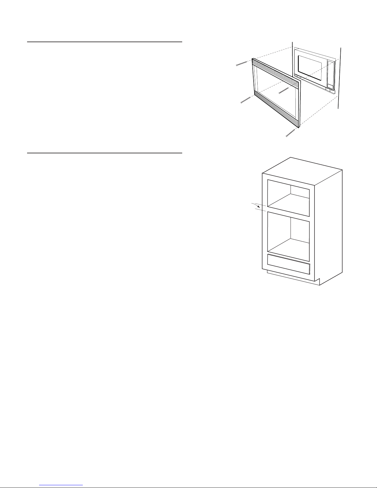
Position the FRAME ASSEMBLY to be square with the
oven. Carefully place the FRAME ASSEMBLY on the oven.
Check that it is level and then secure with two SCREWS
B. See Illustration 5. Secure the bottom portion of the
FRAME ASSEMBLY with the two remaining SCREWS B.
Illustration 5
SCREW B
OVER OVEN INSTALLATION
See Illustration 6.
SCREW B
Illustration 6
2" (5.1 cm) For 27" W
and 30" W lower oven
4" (10.2 cm) For 36" W
lower oven
SCREW B
SCREW B
111 Front Street • Greenwood, Mississippi (MS) 38930 USA • (662) 455-1200
Specifications subject to change without notice.
For more product information, call 1-888-VIKING1 (845-4641), or visit our web site at http://www.vikingrange.com
F20196C (PS0506VR)
TINSEB453MRR0
Viking Range Corporation
 Loading...