

Viking Professional Custom VGSC5304B, Professional VGSC366-4GSS, Professional VGSC367-4GSS, Professional VGSC366-4Q, Professional VGSC366-4QSS Install Manual
...
Viking Installation Guide
Freestanding Gas Self-Clean Ranges
IMPORTANT:
PLEASE READ AND FOLLOW
• Before beginning, please read these instructions
completely and carefully.
• Do not remove permanently affixed labels, warnings, or
plates from the product. This may void the warranty.
• Please observe all local and national codes and
ordinances.
• Please ensure that this product is properly grounded.
• The installer should leave these instructions with the
consumer who should retain for local inspector’s use and
for future reference.
Installation must conform with local codes or, in the
absence of codes, the National Fuel Gas Code, ANSI
N CANADA:
Z223.1 or the latest edition.
must be in accordance with the current CAN/CGA B149.1
& 2 Gas Installation codes and/or local codes. Electrical
installation must be in accordance with the current CSA
C22.1 Canadian Electrical Codes Part 1 and/or local codes.
Installation of any gas-fired equipment should be made by
a licensed plumber. A manual gas shut-off valve must be
installed in the gas supply line ahead of the oven in the gas
stream for safety and ease of service.
I
Installation
WARNING
IF THE INFORMATION IN THIS MANUAL IS
NOT FOLLOWED EXACTLY, A FIRE OR
EXPLOSION MAY RESULT CAUSING PROPERTY
DAMAGE, PERSONAL INJURY, OR DEATH.
1. Do not store or use gasoline or other flammable
vapors and liquids in the vicinity of this or any
other appliance.
W
HAT TO DO IF YOU SMELL GAS:
2.
•Do not try to light any appliance.
•Do not touch any electrical switch; do not use
any phone in your building.
•Immediately call your gas supplier from a
neighbor’s phone.
•Follow the gas supplier’s instructions.
•If you cannot reach your gas supplier, call the fire
department.
3. Installation and service must be performed by a
qualified installer, service agency, or the gas
supplier.
n Massachusetts:
I
“Massachusetts” licensed plumber or gasfitter. A “T”
handle type manual valve must be installed in the gas
supply line to the appliance
All gas products must be installed by a
WARNING
•This range can tip.
•Injury to persons could result.
•Install anti-tip device packed with range.
•See Installation Instructions
WARNING
If not installed, operated and maintained in
accordance with the manufacturer’s instructions,
this product could expose you to substances in fuel
or from fuel combustion which can cause death or
serious illness and which are known to cause
cancer, birth defects, or other reproductive harm.
For example, benzene is a chemical which is
part of the gas supplied to the cooking
product. It is consumed in the flame during
combustion. However exposure to a small
amount of benzene is possible if a gas leak
occurs. Formaldehyde and soot are byproducts of incomplete combustion. Properly
adjusted burners with a bluish rather than
yellow flame will minimize incomplete
combustion.
1
GENERAL INFORMATION
ARNING:
W
•
appliance may result in a potential burn hazard.
Combustible items may ignite, metallic items may become
hot and cause burns. If a cabinet storage is to be provided
the risk can be reduced by installing a rangehood that
projects horizontally a minimum of 5” (12.7 cm) beyond the
bottom of the cabinets.
ARNING:
W
•
heating. This information is based on safety
considerations.
•All openings in the wall behind the appliance and in the
floor under the appliance shall be sealed.
•Keep appliance area clear and free from combustible
materials, gasoline, and other flammable vapors.
•Do not obstruct the flow of combustion and ventilation air.
•Disconnect the electrical supply to the appliance before
servicing. The power disconnect for the sealed top
units is located behind the lower access panel of the
range. This should only be removed by a qualified
service technician.
•When removing oven for cleaning and/or service;
•Electrical Requirement
Listed on Specification sheet. Electrical installation should
comply with national and local codes.
•Gas Manifold Pressure:
•Flexible Connections:
If this unit is to be installed with flexible couplings and/or
quick disconnect fittings, the installer must use a flexible
connector of at least 1/2” ID (1.3 cm) NPT with suitable
strain reliefs and comply with ANSI Z21.41 and Z21.69
standards.
•The misuse of oven doors (e.g. stepping, sitting, or leaning
on them) can result in potential hazards and/or injuries.
The use of cabinets for storage above the
This appliance shall not be used for space
A. Shut off gas at main supply
B. Disconnect AC power supply
C. Disconnect gas line to the inlet pipe.
D. Carefully remove the range by pulling outward.
Natural gas 5.0” W.C.P.
LP/Propane 10.0” W.C.P.
WARNING
ELECTRICAL GROUNDING INSTRUCTIONS
This range must be electrically grounded in
accordance with local codes, or in the absence of
local codes, with the National Electrical Codes,
ANSI/NFPA 70-latest edition. This appliance is
equipped with a three-prong plug for your
protection against shock hazard and should be
plugged directly into a properly grounded
receptacle. Do not cut or remove the grounding
prong from this plug. Do not connect product to
m
GFI circuit. The
proper operation of gas ignition systems. Prior to
servicing, disconnect appliance electrical supply.
For sealed top units the power disconnect is
located behind the lower access panel. This
should only be removed by a qualified service
technician.
F
OR PERSONAL SAFETY, THIS APPLIANCE MUST
inimum
BE PROPERLY GROUNDED
of 102VAC is required for
BACK TRIM ACCESSORIES
Assembly and installation instructions are included
with all back trim accessories.
LEGS
•Legs are packed in styrofoam top pack.
•Legs should be installed near to where the appliance is to
be used, as they are not secure for long transit. After
unpacking the range, raise it about a foot to remove the
bottom shipping skid. Keep the unit raised to permit the
legs to be screwed into our couplings and lower it gently
to keep any undue strain from the legs and internal
mounting hardware. It is strongly recommended that a
pallete or lift jack be used rather than tilting.
N
OTE:
If legs are removed from range and range rests on a
combustible surface, warranty and AGA/CGA
certification are void.
2
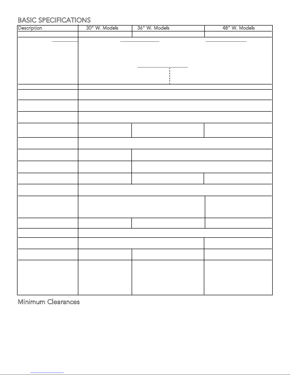
BASIC SPECIFICATIONS
Description 30” W. Models 36” W. Models 48” W. Models
Overall width 29 7/8” (75.9 cm) 35 7/8” (91.1 cm) 47 7/8” (121.6 cm)
Overall height Base Height Open Top Burners Sealed Top Burners
To top of: grate support - burner grate -
Min. 35 7/8 “ (91.1 cm) 37 3/8” (94.9 cm)
Max. 37 5/8” (95.6 cm) 39 1/8” (99.4 cm)
Legs adjust 1 3/4” (4.5 cm) 1 3/4” (4.5 cm)
Additions to Base Height
To top of spider grate - add 1 1/8” (2.9 cm) To top of 10” backguard - add 10” (25.4 cm)
To top of island trim - add 1 1/4” (3.2 cm) To top of high shelf - add 23 1/2” (59.7 cm)
To top of 6” backguard -add 6” (15.2 cm)
Overall depth from rear To end of side panel - 24 15/16” (63.3 cm)
To end of control panel - 27 7/8” (70.8 cm)
To end of knobs - 28 3/8” (72.0 cm)
Electrical requirements 120 VAC/60 Hz; 4 ft. (121.9 cm), 3-wire cord with grounded 3-prong plug attached to
unit.
Gas requirements Shipped natural or LPL/Propane gas; field convertible with conversion kit (purchased
separately); accepts standard residential 1/2” (1.3 cm) ID gas service line.
Maximum amp usage 2.3 amps 6B - 2.3 amps 6G / 4GQ / 4K - 6.4 amps
4G - 6.0 amps 6Q / 4Q / 8B - 2.4 amps
4Q - 2.4 amps 4G - 10.0 amps
Surface burner rating 15,000 BTU Nat. / 13,500 BTU LP
(4.4 kW Nat / 4.0 kW LP)
Griddle burner rating 15,000 BTU Nat. / 13,500 BTU LP
N/A (4.4 kW Nat. / 4.0 kW LP)
Grill burner rating 12” - 1@ 18,000 BTU Nat. (5.3 kW)/ 16,000 BTU LP (4.7 kW)
N/A 24” - 2@ 15,000 BTU Nat. (4.4 kW)/ 13,500 BTU LP (4.0 kW)
Wok burner rating N/A N/A 27,500 BTU Nat. / LP
(8.1 kW Nat. / LP)
Broil rating 18,000 BTU Nat./ 16,000 BTU LP
(5.3 kW Nat. / 4.7 kW LP)
Bake rating 30,000 BTU Nat./LP Right 30,000 BTU Nat./LP
(9.8 kW Nat./LP) (9.8 kW Nat./LP)
Left 15,000 BTU Nat/LP
(4.4 kW Nat.)
Oven Interior width 23” (58.4 cm) 29” (73.7cm) Right - 23” (58.4 cm)
Left - 12 1/8” (30.8 cm)
Oven Interior height 16 18/” (41.0 cm)
Oven Interior depth 15 3/8” (39.1 cm) Right- 15 3/8”(39.1 cm)
Oven Interior overall size 3.3 cu. ft. 4.2 cu. ft. Right - 3.3 cu. ft.
Approximate Shipping wt. 424 lbs. (190.8 kg) 6B - 465 lb. (209.3 kg) 6G - 624 lb. (280.8 kg)
Minimum Clearances
Minimum clearances from the product to adjacent surfaces or construction:
• Below 36” (91.4 cm)
Sides - 0”
Rear - 0”
• Above 36” (91.4 cm)
Sides - 6” (15.2 cm)
Within the 6” (15.2 cm) side clearance, wall cabinets shall be no deeper than 13” (33.0 cm) and must be a
minimum of 18” (45.7 cm) above the countertop.
Left - 17 1/4”(43.8 cm)
Left - 2.1 cu. ft.
4Q - 470 lb. (211.5 kg) 6Q - 620 lb. (279.0 kg)
4G - 475 lb. (213.8 kg) 4G - 634 lb. (285.3 kg)
4Q - 620 lb. (279.0 kg)
4GQ - 629 lb. (283.1 kg)
4K - 624 lb. (280.8 kg)
8B - 620 lb. (279.0 kg)
3
Minimum Clearances (cont.)
Rear - 0” with backguard or high shelf
0” with island trim and non-combustible heat resistant rear wall
6” (15.2 cm) with island trim and combustible rear wall
• Wall cabinets directly above the product must be minimum of 36” (91.4 cm) above the countertop for open top
burners and 42” (106.7 cm) for sealed burners.
To maintain product warranty, the responsibility for ensuring the use of non-combustible heat resistant materials when
required, lies with individual owner, contractor or end user.
*
Use range only with factory supplied legs.
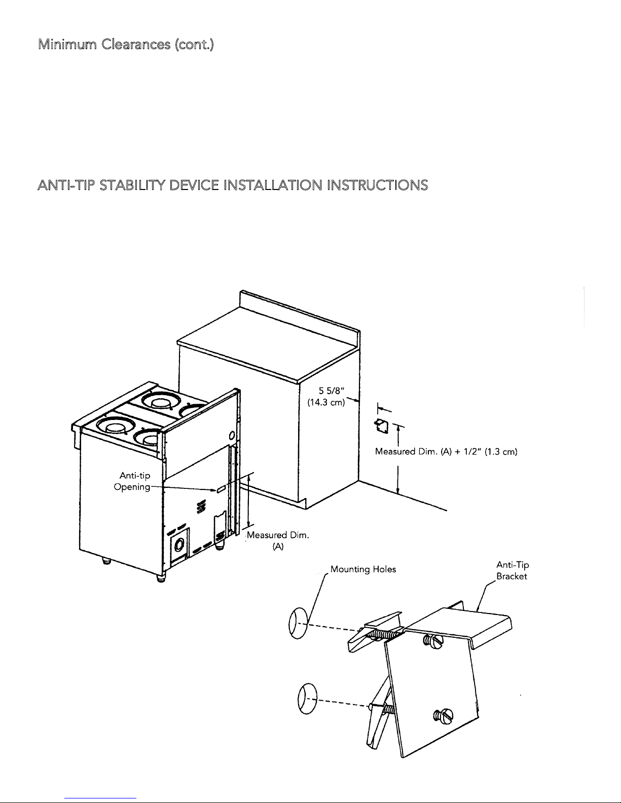
ANTI-TIP STABILITY DEVICE INSTALLATION INSTRUCTIONS
1. The anti-tip bracket is to be attached to the rear wall as shown. The dimension for the bracket location from the
floor is to be determined after the range legs have been adjusted to the proper installation height shown in the
installation instructions and the range has been leveled.
2. Measure from the floor to the bottom of the anti-tip opening located on the back of the range.
3. Locate the anti-tip bracket on the wall at the measure dimension plus 1/2” (1.3 cm) from the floor and 5 5/8” (14.3
cm) from where the left side of the range (facing range) is to be located.
4. Slide range into place making sure the anti-tip bracket slides into the anti-tip opening.
4
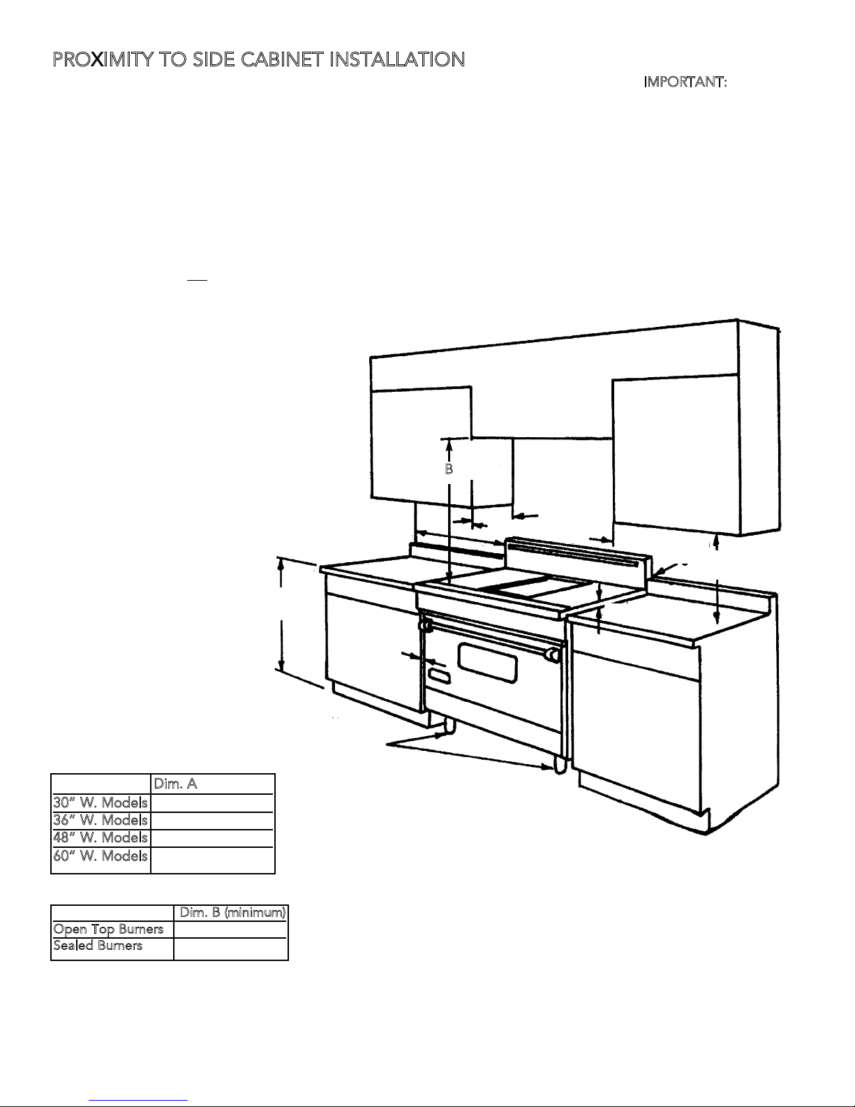
PROXIMITY TO SIDE CABINET INSTALLATION
MPORTANT:
1. This range may be installed directly adjacent to existing 36” (91.4 cm) high base cabinets.
grate support MUST be 3/8” (.95 cm) above the adjacent base cabinet countertop. This may be accomplished by
raising the unit using the adjustment spindles on the legs.
2. The range CANNOT be installed directly adjacent to sidewalls, tall cabinets, tall appliances, or other side vertical
surfaces above 36” (91.4 cm) high. There must be a minimum of 6” (15.2 cm) side clearance from the range to such
combustible surfaces above the 36” (91.4 cm) counter height.
3. Within the 6” (15.2 cm) side clearance to combustible vertical surfaces above 36” (91.4 cm) , the maximum wall
cabinet depth must be 13” (33.0 cm) and wall cabinets within this 6” (15.2 cm) side clearance must be 18” (45.7 cm)
above the 36” (91.4 cm) high countertop.
4. Wall cabinets above the range must be a minimum of 36” (91.4 cm) for open top burner units and 42” (106.7 cm)
for sealed top burner units above the range cooking surface for the full width of the range. This minimum height
requirement does not
apply if a rangehood is installed over the cooking surface.
I
The top
30” W. Models
36” W. Models
48” W. Models
6
0” W. Models
(91.4 cm)
Dim. A
29 7/8” (75.9 cm)
35 7/8” (91.1 cm)
47 7/8” (121.6 cm)
59 1/2” (151.1 cm)
36”
6” Minimum
(15.2 cm)
0” (0.0 cm)
Adjustment
Spindles
B
13” Maximum
(33.0 cm)
A
0”
18” Minimum
(45.7 cm)
3/8” (.95 cm)
Dim. B (minimum)
Open Top Burners
Sealed Burners
36” (91.4 cm)
42” (106.7 cm)
5
 Loading...