

Viking F20508C Installation Manual
Viking Range Corporation
111 Front Street
Greenwood, Mississippi 38930 USA
(662) 455-1200
For product information,
call 1-888-VIKING1 (845-4641)
or visit the Viking Web site at
vikingrange.com
F20508C EN
(112508J)
Viking Installation Guide
Professional Freestanding
30” Electric Range
IMPORTANT
3
2
Table of Contents
Warnings & Important Safety Instructions _______________________________________________3
Dimensions _________________________________________________________________________4
Specifications _______________________________________________________________________5
Clearance Dimensions (Proximity to Cabinets) ___________________________________________6
Clearance Dimensions (Wood/Composite Overlay) ______________________________________7
Electrical Requirements ______________________________________________________________8
General Information__________________________________________________________________9
Installation_________________________________________________________________________10
Door Removal ______________________________________________________________10
Leg Installation______________________________________________________________11
Electrical Connection (3-wire) _________________________________________________12
Electrical Connection (4-wire) _________________________________________________14
Leveling/Adjustments/Alignment ______________________________________________16
Anti-tip Device Installation____________________________________________________17
Final Installation _____________________________________________________________18
Door Replacement and Adjustment ___________________________________________20
Final Preparation ___________________________________________________________________21
Performance Checklist ______________________________________________________________21
Service & Registration _______________________________________________________________22
• Before beginning, please read these
instructions completely and carefully.
• Do not remove permanently affixed labels,
warnings, or plates from product. This may
void the warranty.
• All local and national codes and ordinances
must be observed. Installation must
conform with local codes.
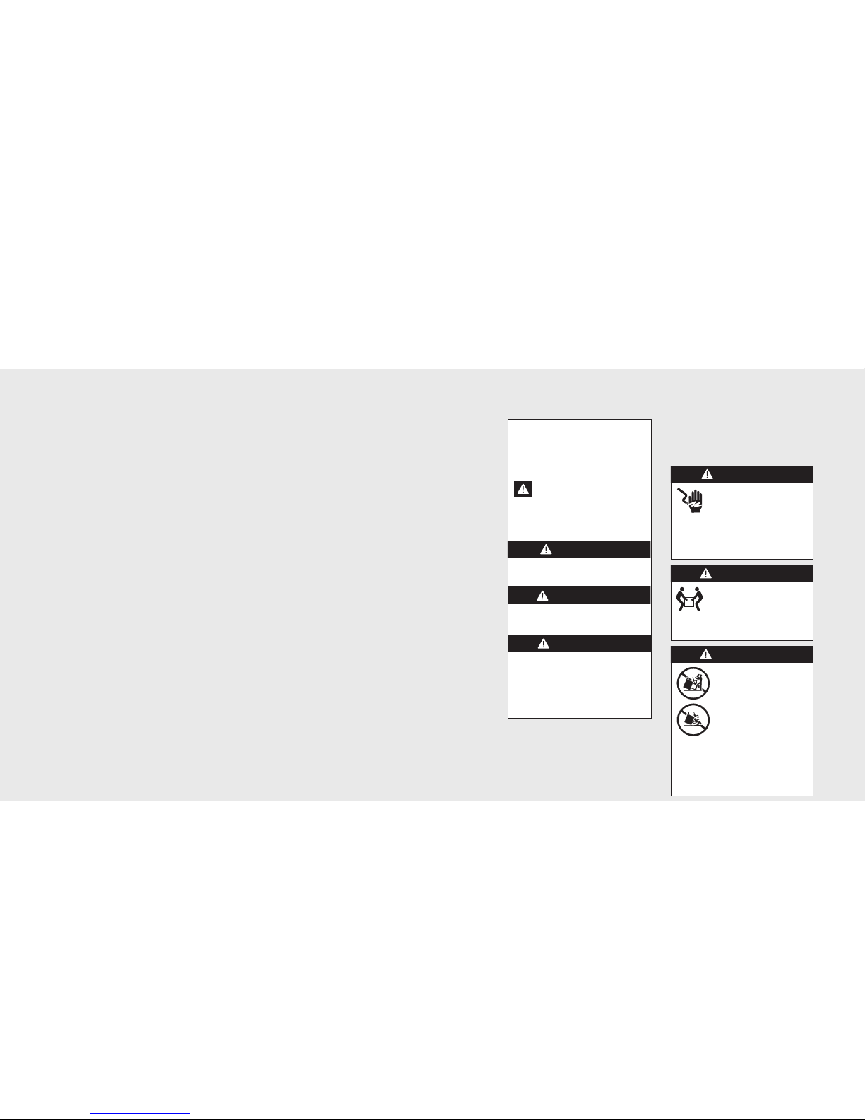
Your safety and the safety of others is
very important.
We have provided many important safety
messages in this manual and on your
appliance. Always read and obey all
safety messages.
This is the safety alert symbol. This
symbol alerts you to hazards that
can kill or hurt you and others.
All safety messages will be preceded by
the safety alert symbol and the word
“DANGER,” “WARNING” or “CAUTION.”
These words mean:
Hazards or unsafe practices
which WILL result in severe personal
injury or death
DANGER
Hazards or unsafe practices
which COULD result in severe personal
injury or death
Hazards or unsafe practices which
COULD result in minor personal injury or
property damage.
All safety messages will identify the
hazard, tell you how to reduce the chance
of injury, and tell you what can happen if
the instructions are not followed.
WARNING
CAUTION
–Read and Follow!
• The installer must leave these instructions
with the consumer who should retain for
local inspector’s use and for future reference.
In Canada: Installation must be in accordance
with the current CSA C22.1 Canadian
Electrical Codes Part 1 and/or local codes.
DANGER
Electrical shock hazard.
To avoid risk of electrical shock,
personal injury or death; verify
your appliance has been
properly grounded in accordance with
local codes or in absence of codes, with
the National Electrical Code (NEC).
ANSI/NFPA 70-latest edition.
WARNING
Moving hazard.
To avoid risk of severe
personal injury; this appliance
requires two or more personnel while
handling and moving. Possible use of
appliance moving devices is recommended.
WARNING
Tipping hazard.
Toreduce the risk of the
appliance tipping, it must be
securedby a properly installed
anti-tip bracket(s). To make sure
the bracket has been installed
properly, look behind the range
with a flashlight to verify proper
installation engaged in the rear
top leftcorner of the range.
• THIS RANGE CAN TIP.
• INJURIES TO PERSONS CAN RESULT.
• INSTALLANTI-TIP DEVICE PACKED
WITH RANGE.
• SEE INSTALLATION INSTRUCTIONS.
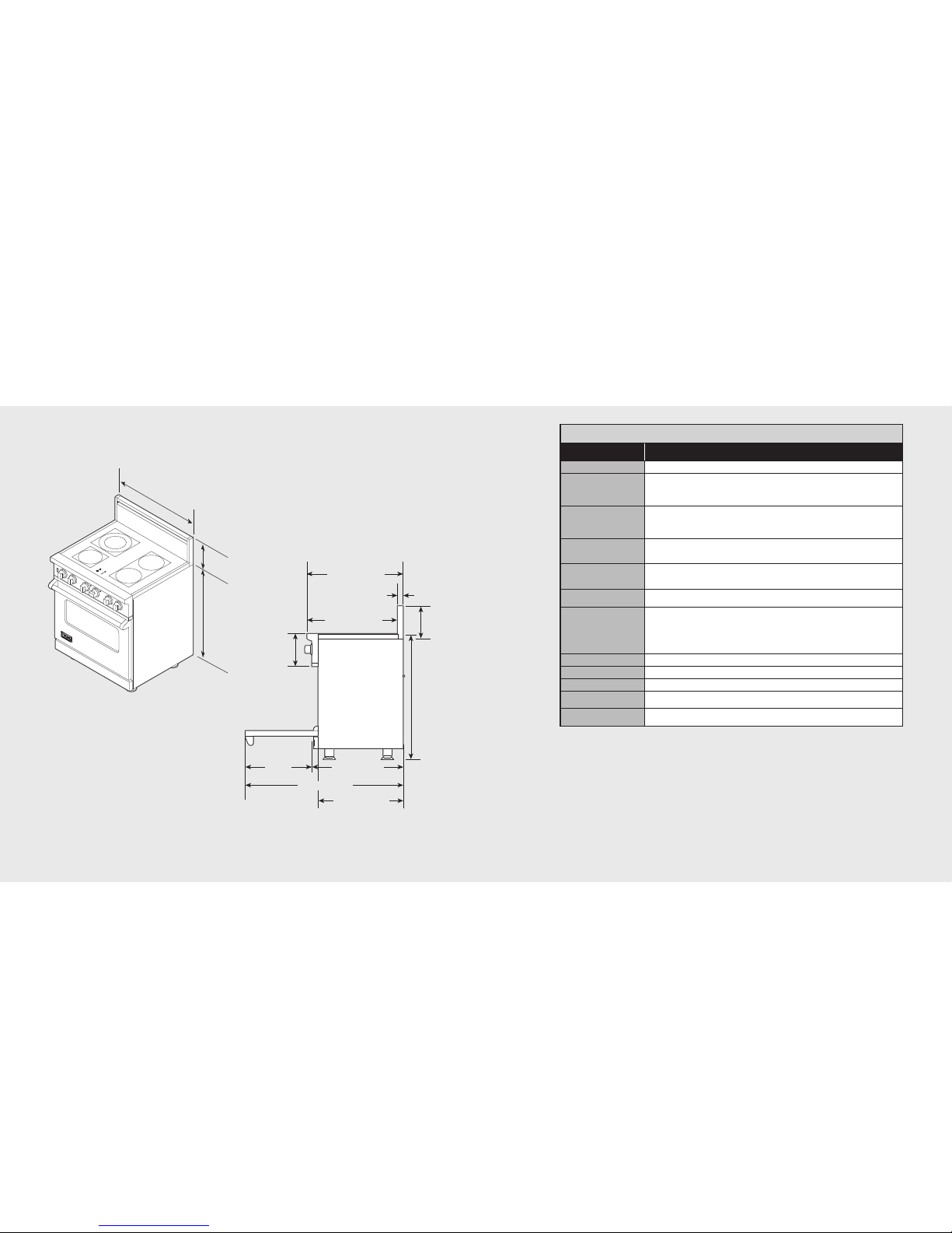
Specifications
5
Dimensions
4
Electric 30” Range
Electric 30” Range
Description
VESC530-4B
Overall width
29-7/8” (75.9 cm)
Overall height To top of glass frame
35-7/8” (91.1 cm) min.
37” (94.0 cm) max.
Legs adjust 1-1/8” (2.9 cm)
Overall depth from
rear
To end of side panel—24-5/16” (61.8 cm)
To front of door—25-3/4” (65.4 cm)
To end of landing ledge—28-1/16” (71.3 cm)
To end of door handle—28-11/16” (72.9 cm)
Additions to base
height
To top of island trim—add 1-1/4” (3.2 cm)
To top of backguard—add 8” (20.3 cm)
To top of high-shelf—add 23-1/2” (59.7 cm)
Electrical
requirements
240-208 VAC, 60 Hz electrical connection box on product, connect with locally
supplied 3-wire, flexible cord or “pigtail” rated 60 amp 125-250 VAC minimum.
Cord must be agency approved for use with household electric ranges.
Maximum amp usage 240V—59.0 amps
208V—51.3 amps
Surface element rating
Left front
Left rear (dual element)
Right front
Bridge
Right rear
1,500 watts
2,500 watts/1000 watts
1,800 watts
800 watts
1,800 watts
Oven interior width
25-5/16” (64.6 cm)
Oven interior height
16-1/2” (41.9 cm)
Oven interior depth
AHAM 16-13/16” (42.7 cm) Overall—19-1/2” (49.5 cm)
Oven volume Total oven capacity—4.7 cu. ft.
Measure to AHAM standards 4.1 cu. ft.
Approximate
shipping weight
426 lbs. (193.2 kg)
2
9
-
7
/
8
”
(
7
5
.
9
c
m
)
3
5
-
7
/
8
”
(
9
1
.
1
c
m
)
m
i
n
.
t
o
3
7
”
(
9
4
c
m
)
m
a
x
.
8
”
(
2
0
.
3
c
m
)
*
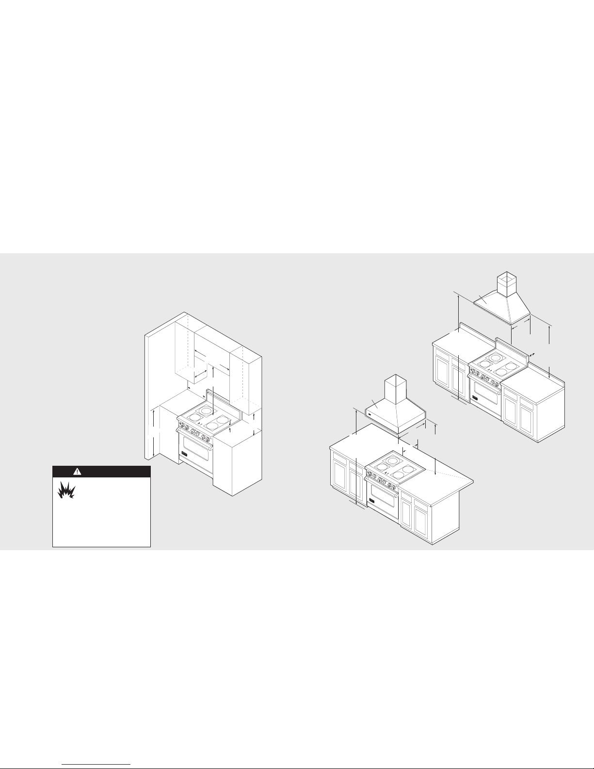
Minimum clearances from adjacent combustible construction
• Cooking surface andbelow, i.e., 36” (91.4 cm) and below
o Sides—0”
o Rear—0” with backguard or highshelf;0” withisland trim and noncombustible rearwall; 6” (15.2 cm) with island
trim and combustible rear wall.
• Above cooking surface, i.e. above 36" (91.4 cm)
o Sides—6” (15.2 cm)
o Within 6” (15.2 cm) side clearance, wall cabinets no deeper than 13” (33.0 cm) must be minimum 18” (45.7 cm)
above cooking surface.
o Wall cabinetsdirectly above product must be minimum 36” (91.4 cm) for open top burnersabove cooking surface.
25-3/4” (65.4 cm)
45-1/8” (114.6 cm)
19-3/8”
(49.2 cm)
8-1/8”
(20.6 cm)
26-7/16” (67.2 cm)
1-5/8”
(4.1 cm)
8”
(20.3 cm)
35-7/8”
(20.3 cm) min.
to
37”
(94 cm) max.
24-5/16” (61.8 cm)
28-1/16” (71.2 cm)
*Note: Unit shown with standard 8” (20.3 cm) backguard.
4
2
”
m
in
.
(
1
0
6
.
7
c
m
)
1
3
”
m
a
x
.
(
3
3
.
0
c
m
)
6
”
m
in
.
(
1
5
.
2
c
m
)
1
8
”
m
in
.
(
4
5
.
7
c
m
)
3
/
8
”
(
0
.
9
5
c
m
)
3
6
”
(
9
1
.
4
c
m
)
2
9
-
7
/
8
”
(
7
5
.
9
c
m
)
Clearance Dimensions (Wood/Composite Overlay)
7
Clearance Dimensions (Proximity to Cabinets)
6
• This range may be installed directly
adjacent to existing 36” (91.4 cm) high
base cabinets.
IMPORTANT: The side trim MUST be
3/8” (.95 cm) above the adjacent base
cabinet countertop. This can be
accomplished by raising the unit using
the adjustment spindles on the legs.
• The range CANNOT be installed
directly adjacent to sidewalls, tall
cabinets, tall appliances, or other
side vertical surfaces above 36”
(91.4 cm) high. There must be a
minimum of 6” (15.2 cm) side
clearance from the range to such
combustible surfaces above the
36” (91.4 cm) counter height.
• Within the 6” (15.2 cm) side
clearance to combustible vertical
surfaces above 36” (91.4 cm), the
maximum wall cabinet depth
must be 13” (33.0 cm) and wall
cabinets within this 6” (15.2 cm)
side clearance must be 18”
(45.7 cm) above the 36”
(91.4 cm) high countertop.
• Wall cabinets above the range must be a
minimum of 42” (106.7 cm) above the
range cooking surface for the full width
of the range. This minimum height
requirement does not apply if a range
hood is installed over the cooking surface.
The bottom of a standard hood should be
30” (76.2 cm) min. to 36” (91.4 cm) max.
above the countertop. This would typically
result in the bottom of the hood being
66” (167.6 cm) to 72” (182.9 cm) above the
floor. Refer to the range hood installation
instructions for additional information. These
dimensions provide for safe and efficient
operation of the hood.
6
6
”
m
in
.
(
1
6
7
.
6
c
m
)
t
o
7
2
”
m
a
x
.
(
1
8
2
.
9
c
m
)
6
6
”
m
in
.
(
1
6
7
.
6
c
m
)
t
o
7
2
”
m
a
x
.
(
1
8
2
.
9
c
m
)
2
4
”
(
6
1
.
0
c
m
)
o
r
2
7
”
(
3
8
.
6
c
m
)
3
0
”
(
7
6
.
2
c
m
)
6
”
(
1
5
.
2
c
m
)
W
o
o
d
/
C
o
m
p
o
si
t
e
O
v
e
r
l
a
y
W
o
o
d
/
C
o
m
p
o
si
t
e
O
v
e
r
l
a
y
3
0
”
m
in
.
(
7
6
.
2
c
m
)
t
o
3
6
”
m
a
x
.
(
9
1
.
4
c
m
)
0
”
(
0
c
m
)
3
0
”
m
in
.
(
7
6
.
2
c
m
)
t
o
3
6
”
m
a
x
.
(
9
1
.
4
c
m
)
Wall Installation
Island Installation
Note: Minimum clearance for back wall is 0” with
backguard or high-shelf.
Note: If a range hood is installed, wall cabinets
above the range have a different minimum
clearance height.
Note: 6” (15.2 cm) min. with island trim and
combustible rear wall. 0” with island trim
and non-combustible rear wall.
Note: Minimum clearance for back wall
is 0” with backguard or high-shelf.
CAUTION
Burn hazard.
To avoid risk of personal injury;
the use of cabinets for storage
above the appliance may result
in a potential burn hazard. Combustible
items may ignite, metallic items may
become hot and cause burns. If a cabinet
storage is to be provided the risk can be
reduced by installing a rangehood that
projects horizontally a minimum 5” (12.7 cm)
beyond the bottom of cabinets.
 Loading...