

Viking F20050 EN Use & Installation Manual
F20500 EN
41010897
(081308J)
Viking Range Corporation
111 Front Street
Greenwood, Mississippi 38930 USA
(662) 455-1200
For product information,
call 1-888-VIKING1 (845-4641)
or visit the Viking Web site at
vikingrange.com
Viking Use/Installation Guide
Undercounter/Freestanding Wine Cellars

3
GENERAL INFORMATION
UUnn ppaacckk
1. Remove banding from bottom of carton. Lift carton up and off of the wine cellar
2. Remove all tape and packaging material from the outside and inside of the cabinet.
3. Keep all carton packaging until your wine cellar has been thoroughly inspected and found to be in good condition.
AARREEAA RREEQQUUIIRREEMMEENNTTSS
1. Place unit so the front side will be completely unobstructed to provide proper air flow. The unit may be closed in
on the top and three sides, but the front
MMUUSSTT BBEE
unobstructed for air circulation and proper operation.
Installation should be such that the cabinet can be moved for servicing if necessary.
2. Unit should be in a well ventilated area with temperature above 55°F (13°C) and below 110°F (43°C). Best results
are obtained at temperatures between 65°F (18°C) and 80°F (27°C) for built-in models and 65°F (18°C) and 90°F
(32°C) for freestanding models.
3. Provisions for electricity should be determined before placing unit in proper place.
A
B
C
UUNNDDEERRCCOOUUNNTTEERR CCAABBIINNEETT CCUUTTOOUUTT
IMPORTANT - PLEASE READ AND FOLLOW
••
Before beginning, please read these instructions completely and carefully.
• Do not remove per manently affixed labels, warnings, or plates from the product. This may void the warranty.
• Please observe all local and national codes and ordinances.
• Please ensure that this product is properly grounded.
• The installer should leave these instructions with the consumer who should retain for local inspector’s use and for
future reference.
WARNING
::
TToo rreedduuccee tthhee rriisskk ooff ffiirree,, eelleeccttrriiccaall sshhoo cckk,, oorr iinnjjuurryy wwhheenn uussiinngg yyoouurr wwiinnee cceellllaarr,, ffoollllooww bbaassiicc pprreeccaauuttiioonnss iinncclluuddiinngg tthhee
ffoolllloowwiinngg::
•FOR YOUR SAFETY•
DO NOT STORE OR USE GASOLINE OR OTHER FLAMMABLE VAPORS AND LIQUIDS IN THE VICINITY OF THIS OR
ANY OTHER APPLIANCE. THE FUMES CAN CREATE A FIRE HAZARD OR EXPLOSION.
IItt iiss yyoouurr rreessppoonnssiibbii lliittyy tt oo bbee ssuurree yyoouurr wwiinnee cceellllaarr iiss::
•located so the front is not blocked to restrict incoming or discharge air flow.
•properly leveled.
•located in a well ventilated area.
•connected to the proper kind of outlet, with the correct electric supply and grounding. A 115 volt, 60 Hz, 15 amp
fused electrical supply is required.
NNOOTTEE::
Time delay fuse or circuit breaker is recommended.
•not used by anyone unable to operate it properly.
•used only for its intended purpose.
•properly maintained.
•SAVE THESE INSTRUCTIONS•
SUFFOCATION HAZARD
Remove doors from your old refrigeration unit.
Failure to do so can result in child entrapment,
which can cause death or brain damage.
IMPORTANT: Child entrapment and suffocation are not problems of the
past. Junked or abandoned refrigeration products are still dangerous,
even if they will sit for “just a few days.” If you are getting rid of your
refrigeration product, please follow the instructions below to help prevent
accidents.
BEFORE YOU THROW AWAY YOUR OLD REFRIGERATION UNIT:
•Take off the doors.
•Leave the shelves in place so that children may not easily climb inside.
PROPER DISPOSAL OF YOUR OLD REFRIGERATION UNIT
2
DANGER
24” W. Models
15” W. Models
*Add 1/4” (.64 cm) to cutout width if door is recessed between
cabinets.
A 15” (38.1 cm)* 24” (61.0 cm)*
B
Min. 34 1/2” (87.6 cm)
Max. 35 1/8” (89.2 cm)
Min. 34 1/2” (87.6 cm)
Max. 35 1/8” (89.2 cm)
C 24” (61.0 cm) 24” (61.0 cm)
UUnn iittss CCeerrttiiffiieedd ffoorr OOuuttddoooorr UUssee -- ((ssttaaiinnlleessss sstteeeell oouutteerr ccaabbiinneett))
1. Place unit so the front side will be completely unobstructed to provide proper air flow. The unit may be closed in
on the top and three sides, but the front
MMUUSSTT BBEE
unobstructed for air circulation and proper operation.
Installation should be such that the cabinet can be moved for servicing if necessary.
2. Unit should be in a well ventilated area with temperature above 40°F (4.4°C) and below 110°F (43°C). Best results
are obtained at temperatures between 60°F (16°C) and 100°F (38°C).
3. Provisions for electricity should be determined before placing unit in proper place.
54
SPECIFICATIONS/DIMENSIONS
PROFESSIONAL - 15” W. Models
BBaassiicc EElleeccttrriicc DDaatta
a
•
115 VAC/60 Hz
•
Maximum amps - 3.0
•
Approximate Shipping Weight - 110 lbs. (49.5 kg)
SPECIFICATIONS/DIMENSIONS
DESIGNER - 15” W. Models
BBaassiicc EElleeccttrriicc DDaatta
a
•
115 VAC/60 Hz
•
Maximum amps - 3.0
•
Approximate Shipping Weight - 110 lbs. (49.5 kg)
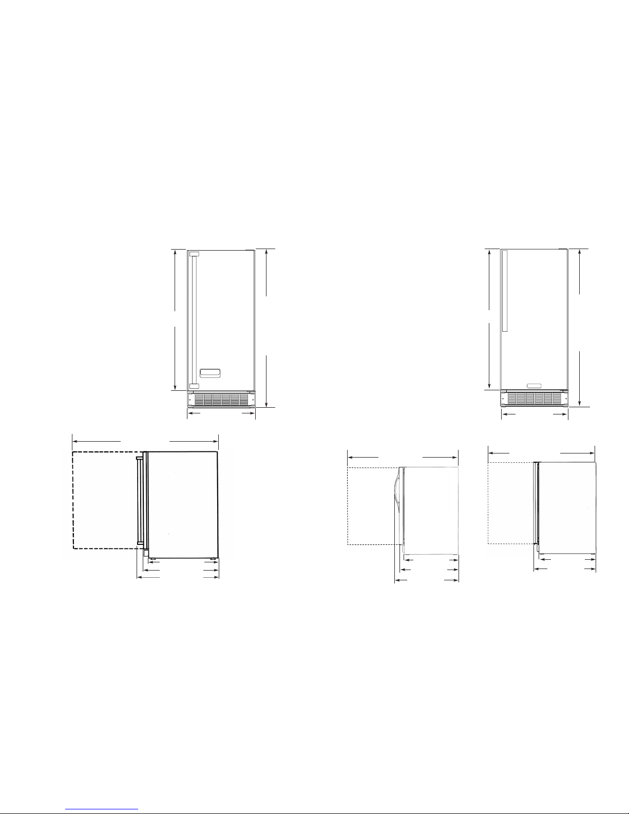
Front View
Side View
30 3/4”
(78.1 cm)
Min. 34 1/4”
(87.0 cm)
to
Max. 35”
(88.9 cm)
(with leveling
legs fully
extended.)
14 3/4” (37.5 cm)
21 3/16” (53.8 cm)
23 5/8” (60.0 cm)
26 1/8” (66.4 cm)
37 3/16” (94.5 cm)
Front View
Side View
DUWC
Side View
DFUW
30 3/4”
(78.1 cm)
Min.
34 1/4”
(87.0 cm)
Max.
35”
(88.9 cm)
(with leveling
legs fully
extended.)
14 3/4” (37.5 cm)
21 3/16” (53.8 cm)
23 5/8” (60.0 cm)
24 5/8” ( 62.5 cm)
21 3/16” (53.8 cm)
23 7/16” (59.5 cm)
37 3/16” (94.5 cm)
37 3/16” (94.5 cm)
(to front of locally supplied
custom panel
7
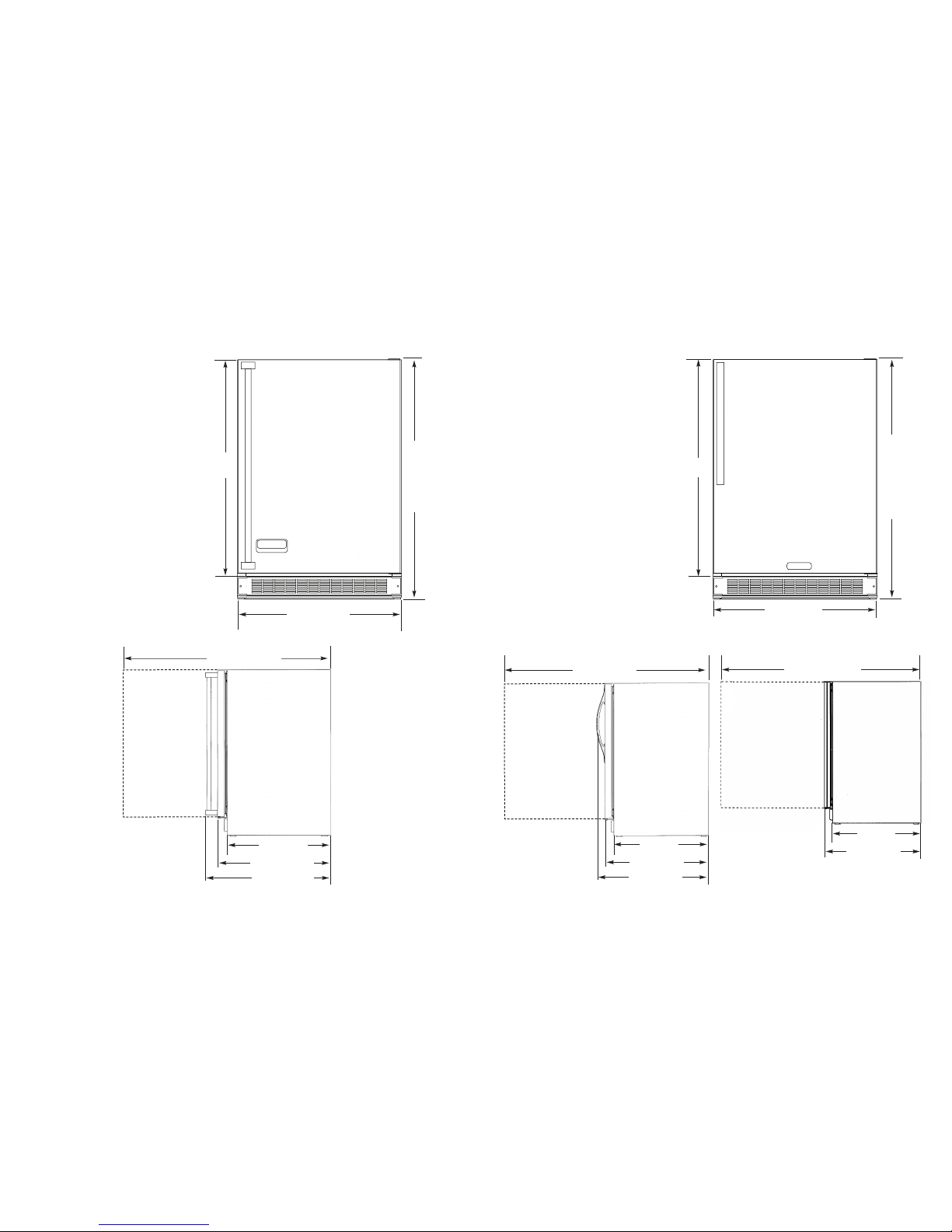
SSPPEECCIIFFIICCAATTIIOONNSS//DDIIMMEENNSSIIOONNSS
DESIGNER - 24” W. Models
BBaassiicc EElleeccttrriicc DDaattaa
•115 VAC/60 Hz
•Maximum amps - 3.3
•Approximate shipping weight - 140 lbs (63.2 kg)
Front View
30 3/4”
(
78.1 cm)
Min.
34 1/4”
(87.0 cm)
M
ax.
35”
(88.9 cm)
with leveling
legs fully
extended
23 7/8” (60.6 cm)
Side View
DUWC
22” (55.9 cm)
24 3/8” (61.9 cm)
25 3/8” ( 64.5 cm)
47 1/4” (120.0 cm)
Side View
DFUW
22” (55.9 cm)
24 3/16” (61.4 cm)
47 1/4” (120.0 cm)
(to front of locally supplied
custom panel
6
SPECIFICATIONS/DIMENSIONS
PROFESSIONAL - 24” W. Models
BBaassiicc EElleeccttrriicc DDaatta
a
•
115 VAC/60 Hz
•
Maximum amps - 3.3
•
Approximate Shipping Weight - 140 lbs. (63.2 kg)
Min. 34 1/4”
(87.0 cm)
t
o
M
ax 35”
(88.9 cm) with
leveling legs
fully
extended
30 3/4”
(78.1 cm)
23 7/8” (60.6 cm)
47 1/4” (120.0 cm)
22” (55.9 cm)
24 3/8” (61.9 cm)
26 7/8” (68.3 cm)
Front View
Side View
98
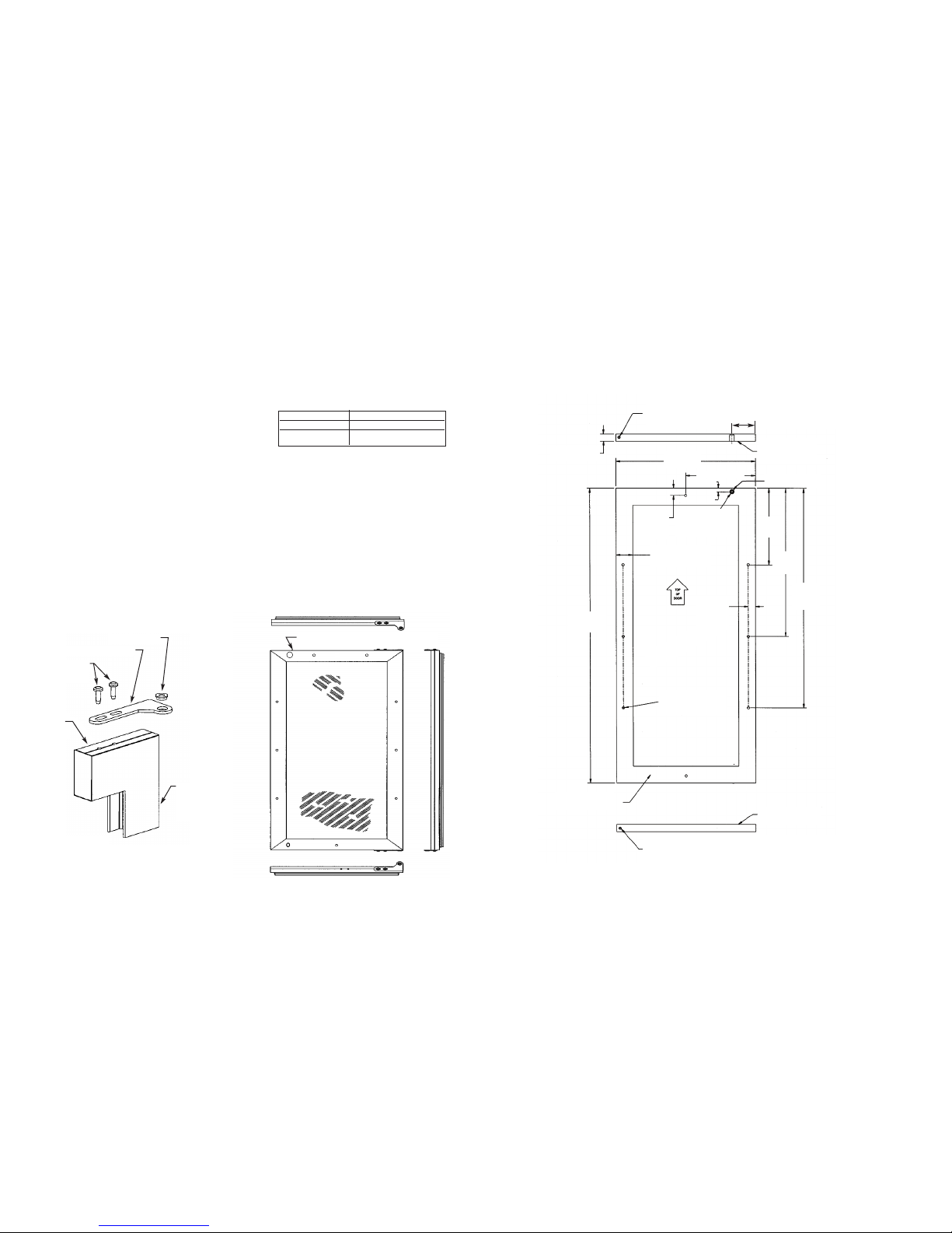
CCUUSSTTOOMM WWOOOODD FFRRAAMMEE IINNSSTTAALLLLAATTIIOONN IINNSSTTRRUUCCTTIIOONNSS
((DDFFUUWW MMooddeell))
Note: Weight of wood panel must not exceed 20 lbs.
WWoooodd SSccrreewws
s
1
. A #10 pan head wood screw should be used to properly secure the wood frame. A total of 10 screws will be needed.
2
. Only use pan head screws.
3. DO NOT select a screw that is longer than the wood thickness at
the screw locations.
4. Use recommended pilot holes for the frame material. (See chart)
WWoorrkkiinngg MMaatteerriiaall WWoooodd SSccrreeww SSiizzee ##1100
Hardwood 3/32 (0.24 cm)
Softwood 5/64 (0.20 cm)
AAsssseemmbbll iinngg DDoooorr HHiinnggee BBrraacckkeettss
(Disregard if hinge brackets are already attached)
1. Attach the top and bottom door hinge brackets to the door with the #10-32 machine screws and a 1/8” allen head
driver as shown in Figure 1 below.
2. Press in the shoulder bushings to the top and bottom door hinge brackets. Make certain that the shoulder is to the
outside of the door as shown in Figure 1 below.
3. Test fit the door to the unit to make certain door will hang correctly. The door is hung correctly when the top of the
door is parallel to the top of the unit. (See Figure 2) Adjustments can be made by loosening the door hinge
machine screws and moving the door hinge brackets on the door.
4. Tighten all four (4) machine screws after adjustments have been made.
5. Remove the door from the unit by removing the units top hinge set screw and angling the door off of the bottom
hinge pin.
Figure 1
Shoulder Bushing
Door Hinge Bracket
#10-32 Machine
Screw
Door Hinge
Screw Holes
Door Front
Surface
TTyyppiiccaall TToopp aanndd BBoottttoomm
DDoooorr HHiinnggee BBrraacckkeett
AAsssseemmbbllyy
Figure 2
This surface parallel to the unit.
(Right hinge door shown.)
Selecting and Preparing the Wood Frame - 15” W. DFUW Model
FFOORR AA 33--11//22”” TTOOEE KKIICCKK
((CCOOVVEERRSS TTHHEE EENNTTIIRREE DDOOOORR EEXXTTRRUUSSIIOONN))
((LLEEFFTT HHIINNGGEE))
1/4” X 3/8” Deep hinge screw clearance hole
-Locate and drill using door hinge hole after the door has been aligned
to the unit and when the wood is positioned on door.
1/4” X 3/8” Deep hinge screw clearance hole. Locate and drill using
door hinge hole after the door has been aligned to the unit and
when the wood is positioned on door.
M
ounting surface
(
Non-face) side
Mounting surface
(non-face) side
Mounting surface
(non-face) side
M
in. 5/8” (1.7 cm)
M
ax. 3/4” (1.9 cm)
1
4 5/16”
(
36.4 cm)
7 5/32” (18.2 cm)
23/32”
(1.8 cm) TYP
1
23/32” (4.4) cm min.
width to cover door
e
xtrusion
23/32”
(1.8 cm)
TYP
B
A
CK
V
IEW
O
F
O
V
ER
L
A
Y
PA
N
EL
30 5/16”
(77.0 cm)
Pre-drilled pilot holes 8 places
7
13/16”
(
19.8 cm)
TYP
15 5/32”
(38.5 cm)
TYP
22 1.2”
(57.2 cm)
TYP
13/16” (2.1 cm)
counterbore 7/16”
(
1.1 cm) deep
1
5/32” (1.2 cm)
D
ia. hole
15./2” (1.2 cm)
3 7/32”
(
8.1 cm)
 Loading...