

Page 1
May 7, 2014
Deluge Valves 218a
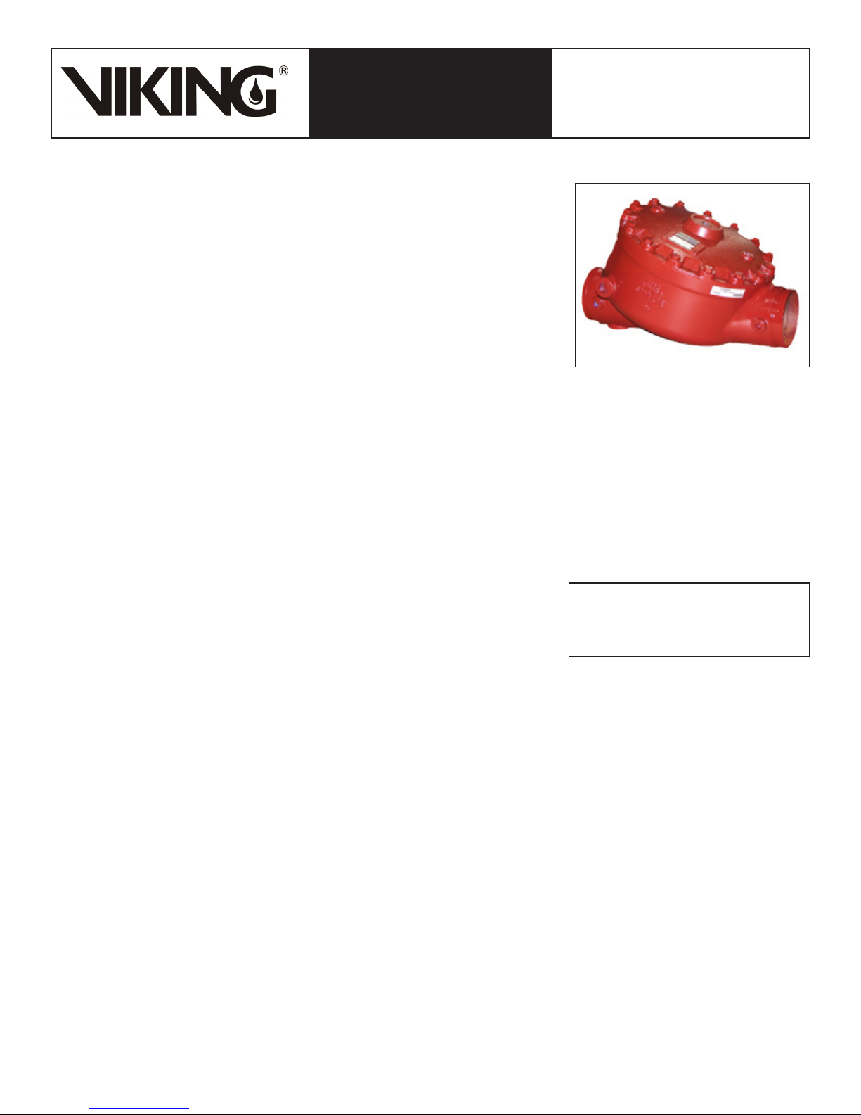
DELUGE VALVE, MODEL F-1
TECHNICAL DATA
The Viking Corporation, 210 N Industrial Park Drive, Hastings MI 49058
Telephone: 269-945-9501 Technical Services: 877-384-5464 Fax: 269-818-1680 Email: techsvcs@vikingcorp.com
1. DESCRIPTION
The Viking Model F-1 Deluge Valve is a quick opening, differential diaphragm and flood
valve with one moving mechanism. The Deluge Valve is used to control water flow in
Deluge and Preaction sprinkler systems. The valve is held closed by system water pressure trapped in the priming chamber; keeping the outlet chamber and system piping
dry. In fire conditions, when the releasing system operates, pressure is released from
the priming chamber. The Deluge Valve clapper opens to allow water to flow into the
system piping.
Features:
Field replaceable Diaphragm and Seat Rubbers
1.
Designed for installation in the horizontal or vertical position
2.
Designed to be reset without opening the valve
3.
Compatible with Hydraulic, Pneumatic and/or Electric Release Systems
4.
NOTE: FOR PART NUMBERS OF ACCESSORIES, REFER TO VIKING LIST PRICE SCHEDULE.
2. LISTINGS AND APPROVALS:
U.L. Listed - Guide No. VLFT & VLJH
C-UL Listed
FM Approved - Deluge Sprinkler Systems, Preaction Sprinkler Systems, Refrigerated Area Sprinkler Systems
American Bureau of Shipping (ABS) - Certificate No. 05-HS502910C-PDA
NYC Department of Buildings - MEA 89-92-E Vol XXXI
CE - Pressure Equipment Directive 97/23/EC
STRAIGHT THROUGH STYLE
2-1/2” (DN65) - 8” (DN200)
3. TECHNICAL DATA
Specifications:
Maximum Working Water Pressure: 250 PSI (17.4 bar)
Style: Straight through
Connections: See Table 1.
Factory tested: to 500 psi (34.5 bar)
Valve differential: 2:1 (priming chamber to inlet chamber)
Priming chamber supply restriction (required): 0.0625” (1.6 mm)
Color of Valve: Red
Friction loss: Refer to Table 1.
Cv Factor: Refer to Table 1.
Material Standards:
Refer to Figure 2.
Ordering Information:
Part Numbers - Refer to Table 1
8” - Manufactured since 2002
4” & 6” - Manufactured since 2003
2-1/2” & 3” - Manufactured since 2004
ACCESSORIES:
Refer to Current VIKING PRICE LIST for Part Numbers.
A Conventional Trim Trim package for use with the Model F-1 Deluge Valve. The trim package includes the VALVE ACCESSORY
1.
PACKAGE and the fittings and nipples shown on the Viking Deluge Valve Conventional Trim Chart Trim Chart for the valve used.
Trim Charts are provided in trim packages and the Viking Engineering and Design Data book. For optional factory assembled
“modular” trim packages, refer to the Viking list price schedule or contact the manufacturer.
A Deluge VALVE ACCESSORY PACKAGE includes required trim components. This package is needed when Viking Trim
2.
Packages are not used.
Auxiliary Components are required for specific valve functions. For complete operating trim requirements, refer to system data
3.
for the system used. System data is provided in the Viking Engineering and Design Data book.
Additional accessories are available and may be required for system operation or supervision. Refer to the system description and
technical data for complete operating trim requirements for the system used.
Viking Technical Data may be found on
The Viking Corporation’s Web site at
http://www.vikinggroupinc.com.
The Web site may include a more recent
edition of this Technical Data Page.
Form No. F_110802
Replaces page 218a-j, dated April 15, 2011.
(Updated friction loss and weight values fo DN150 FF)
Page 2
Deluge Valves 218b
May 7, 2014
DELUGE VALVE, MODEL F-1
TECHNICAL DATA
The Viking Corporation, 210 N Industrial Park Drive, Hastings MI 49058
Telephone: 269-945-9501 Technical Services: 877-384-5464 Fax: 269-818-1680 Email: techsvcs@vikingcorp.com
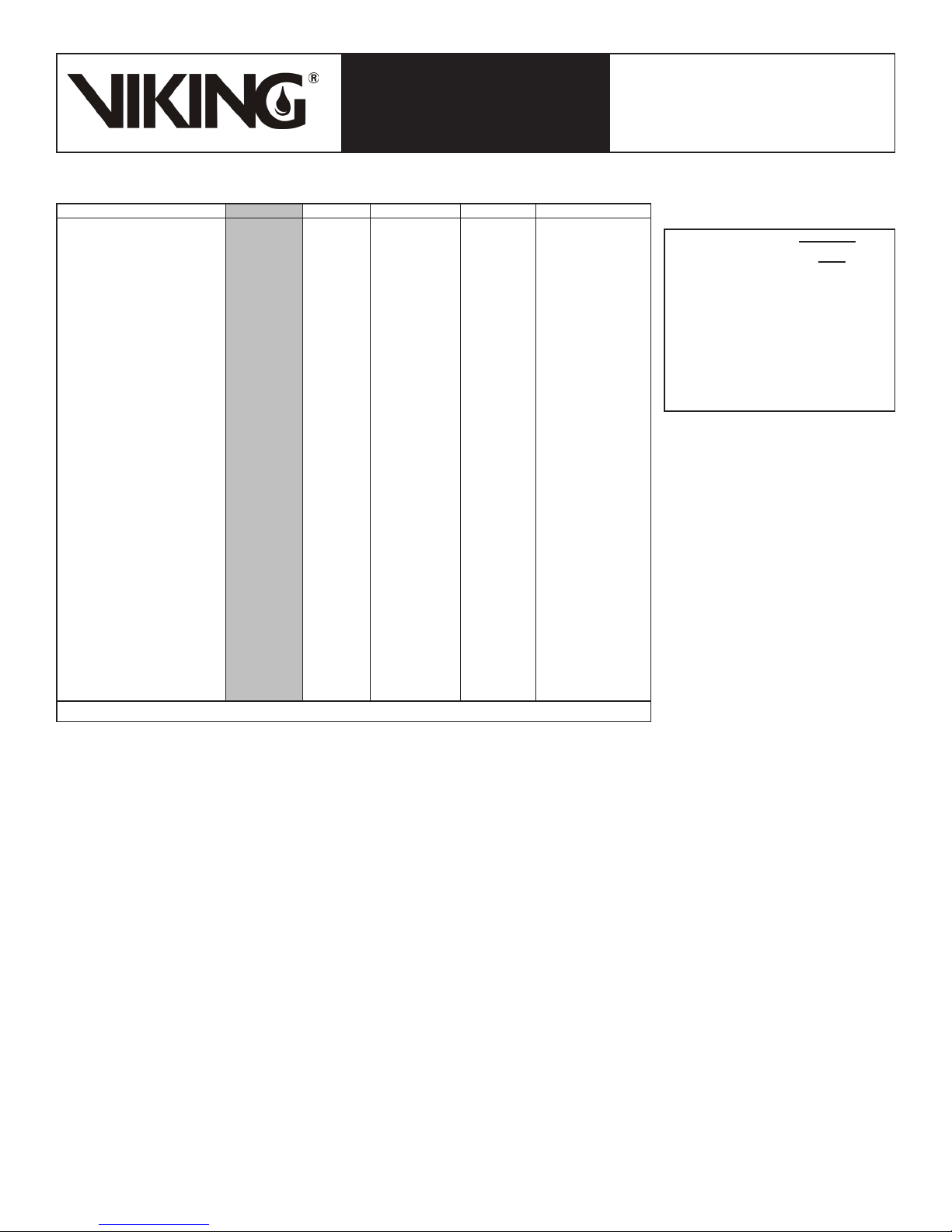
DESCRIPTION Nominal Size Part Number Friction Loss* Cv Factor Shipping Weight
Threaded
Flange/Flange
Flange/Groove
Flange Drilling / Pipe O.D.
Groove/Groove
*Expressed in equivalent length of Schedule 40 pipe based on Hazen & Williams C=120
4. INSTALLATION (Refer to Figure 1 identification of trim components.)
A. General Instruction
Viking Straight Through Deluge Valves may be installed in the horizontal or vertical position.
1.
The valve must be installed in an area not subject to freezing temperatures or physical damage.
2.
The valve must be trimmed according to current Viking Trim Charts and appropriate instructions for the system used. Trim Charts
3.
are printed in the Viking Engineering and Design Data book, and are provided with trim packages.
Remove all plastic protectors from the openings of the Deluge Valve.
a.
Apply a small amount of pipe joint compound or tape to the external threads of all pipe connections required. Take care not to
b.
allow any compound, tape, or other foreign matter inside any of the nipples or openings of the valve or trim components.
Viking Model F-1 Deluge Valve Conventional Trim Charts are provided with Trim Packages and in the Viking Engineering and
c.
Design Data book.
Verify that all system components are rated for the water working pressure of the system.
d.
Hydrostatic Test:
The Model F-1 Deluge Valve is manufactured and listed for use at a maximum Water Working Pressure of 250 PSI (17.2 bar). The
valve is factory tested at 500 PSI (34.5 bar). Model F-1 Deluge Valves may be hydrostatically tested at 300 PSI (20.7 bar) and/or 50
PSI (3.4 bar) above the normal Water Working Pressure, for limited periods of time (two hours), for the purpose of acceptance by the
Authority Having Jurisdiction. If air testing is required, do not exceed 60-PSI (4.1 bar) air pressure.
NOTE: NEVER CONDUCT THE HYDROSTATIC TEST AGAINST THE PRESSURE OPERATED RELIEF VALVE. (P.O.R.V.) TEMPORARILY REMOVE THE P.O.R.V. FROM THE TRIM AND PLUG TRIM OPENINGS WHILE CONDUCTING THE HYDROSTATIC TEST.
TRIM NOTE: DISCHARGE PIPING FROM THE AUXILIARY DRAIN VALVE, THE FLOW TEST VALVE, AND ALL SYSTEM DRAINS
SHOULD BE KEPT SEPARATE. DO NOT CONNECT THE OUTLET OF THE DRIP CHECK TO ANY OTHER DRAIN.
The priming line must be connected upstream of the system water supply main control valve or to a constant source of water at
4.
a pressure equal to the system water supply.
Pipe O.D.
NPT 65 mm 2½" 12401 12 ft. (3.6 m) 155 67 lbs. (30 kg)
Flange Drilling
ANSI 3" 12014 12 ft. (3.6 m) 155 82 lbs. (37 kg)
ANSI 4" 11953 21 ft. (6.5 m) 428 146 lbs. (66 kg)
ANSI 6" 11955 39 ft. (11.9 m) 839 271 lbs. (123 kg)
ANSI 8" 11991 57 ft. (17.4 m) 1577 466 lbs. (212 kg)
ANSI/Japan 6" 11964 39 ft. (11.9 m) 839 271 lbs. (123 kg)
PN10/16 DN80 12026 12 ft. (3.6 m) 155 82 lbs. (37 kg)
PN10/16 DN100 11965 21 ft. (6.5 m) 428 127 lbs. (58 kg)
PN10/16 DN150 11956 39 ft. (11.9 m) 839 271 lbs. (123 kg)
PN10 DN200 11995 57 ft. (17.4 m) 1577 418 lbs. (190 kg)
PN16 DN200 11999 57 ft. (17.4 m) 1577 466 lbs. (212 kg)
ANSI / 89 mm 3" 12018 12 ft. (3.6 m) 155 75 lbs. (34 kg)
ANSI / 114 mm 4" 11952 21 ft. (6.5 m) 428 136 lbs, (62 kg)
ANSI / 168 mm 6" 11954 39 ft. (11.9 m) 839 261 lbs. (118 kg)
PN10/16 / 89 mm DN80 12030 12 ft. (3.6 m) 155 75 lbs. (34 kg)
PN10/16 / 114 mm DN100 11958 21 ft. (6.5 m) 428 136 lbs. (62 kg)
PN10/16 / 165 mm DN150 12640 39 ft. (11.9 m) 839 261 lbs. (118 kg)
PN10/16 / 168 mm DN150 11954 39 ft. (11.9 m) 839 261 lbs. (118 kg)
Pipe O.D.
73 mm 2½" / DN65 12403 12 ft. (3.6 m) 155 67 lbs. (30 kg)
76 mm DN80 12729 12 ft. (3.6 m) 155 67 lbs. (30 kg)
89 mm 3" / DN80 12022 12 ft. (3.6 m) 155 64 lbs. (29 kg)
114 mm 4" / DN100 11513 21 ft. (6.5 m) 428 127 lbs. (58 kg)
165 mm DN150 11910 39 ft. (11.9 m) 839 245 lbs. (111 kg)
168 mm 6" / DN150 11524 39 ft. (11.9 m) 839 245 lbs. (111 kg)
219 mm 8" / DN200 11018 57 ft. (17.4 m) 1577 403 lbs. (183 kg)
STRAIGHT THROUGH STYLE
2-1/2” (DN65) - 8” (DN200)
∆P
Q= Cv
Q= Flow
Cv= Flow Factor (GPM/1 PSI ∆P)
∆P= Pressure Loss through Valve
S= Specific Gravity of Fluid
Table 1 - Valve
Part Numbers and
Specifications
√
S
Page 3

May 7, 2014
Deluge Valves 218c
DELUGE VALVE, MODEL F-1
TECHNICAL DATA
The Viking Corporation, 210 N Industrial Park Drive, Hastings MI 49058
Telephone: 269-945-9501 Technical Services: 877-384-5464 Fax: 269-818-1680 Email: techsvcs@vikingcorp.com
After the Deluge Valve is set, operation of the Deluge Valve requires the release of priming water from the priming chamber. This
5.
may be by automatic or manual operation of the release system. Viking Deluge Valves are compatible with hydraulic, pneumatic,
and electric release systems. For specific Trim arrangements refer to Trim Charts and System Data describing the system being
installed. Trim Charts are printed in the Viking Engineering and Design Data book, and are provided with trim packages. System
Data sheets are printed in the Viking Engineering and Design Data book.
Hydraulic Release Systems: See Figures 3-6 for the maximum allowable elevation of hydraulic release piping above the
a.
Deluge Valve. If the maximum height of hydraulic release piping exceeds the limit shown in Figures 3-6 for the valve used,
use a Pneumatic or Electric Release System.
Pneumatic Release Systems: A Viking Pneumatic Actuator is required between the release system connection provided on
b.
deluge valve trim and pneumatic release system piping.
Electric Release Systems: Solenoid Valves, System Control Panels, and Electrical Detectors must be compatible. Consult
c.
appropriate listing and/or approval guides.
NOTE: FOR OPERATION AT WATER PRESSURES IN EXCESS OF 175 PSI (12.1 BAR), A 250 PSI (17.2 BAR) RATED SOLENOID VALVE
MUST BE USED. REFER TO APPROPRIATE VIKING TECHNICAL DATA PAGE FOR TYPE OF SYSTEM USED.
CAUTION: OPERATION OF VIKING DELUGE VALVES BY PRESSURIZING THE PRIMING CHAMBER WITH AIR PRESSURE OR ANY
OTHER PRESSURIZED GAS IS NOT RECOMMENDED OR APPROVED.
STRAIGHT THROUGH STYLE
2-1/2” (DN65) - 8” (DN200)
B. Placing the Valve in Service
For Deluge Valves equipped with Conventional Deluge Valve Trim, follow steps 1 through 10 (and 11 & 12 if applicable) below.
Verify:
1.
The system Main Water Supply Control Valve (D.1) is closed and the Deluge Valve is trimmed according to current Viking Trim
a.
Charts and schematic drawings for the system used.
The system has been properly drained.
b.
Auxiliary Drain (B.13) is open.
c.
The Emergency Release (B.9) is closed.
d.
The system water supply piping is pressurized up to the closed Main Water Supply Control Valve (D.1) and the priming line
e.
is pressurized up to the closed Priming Valve (B.1).
For Systems equipped with:
2.
Hydraulic Release Systems:
a.
Verify that all releasing devices are set and that any Inspector’s Test Valve and/or auxiliary drain valves are closed.
i.
Open Priming Valve (B.1).Allow the hydraulic release system to fill. When priming pressure gauge (B.7) indicates that the
ii.
release piping and priming chamber pressure is equal to system supply pressure, proceed to step 3.
Proceed to step 3.
iii.
Pneumatic Release Systems:
b.
Set the release system.
i.
Open Priming Valve (B.1).
ii.
Proceed to step 3.
iii.
Electric Release Systems:
c.
Open Priming Valve (B.1).
i.
Set the electric release system.
ii.
Proceed to step 3.
iii.
Open Flow Test Valve (B.11).
3.
Partially open Main Water Supply Control Valve (D.1).
4.
When full flow develops from the Flow Test Valve (B.11), close the Flow Test Valve. Verify that there is no flow from the open
5.
Auxiliary Drain (B.13).
Close Auxiliary Drain (B.13).
6.
Fully open and secure the Main Water Supply Control Valve (D.1).
7.
Verify that the Alarm Shut-off Valve (B.6) is open and that all other valves are in their normal** operating position.
8.
Depress the plunger of Drip Check (B.14). No water should flow from the Drip Check when the plunger is pushed.
9.
Check for, and repair all leaks.
10.
On new installations, those systems that have been placed out of service, or where new equipment has been installed, trip test
11.
the system to verify that all equipment functions properly. Refer to INSPECTION, TESTS AND MAINTENANCE paragraph 6-II-C:
ANNUAL Trip Test instructions.
CAUTION! PERFORMING A TRIP TEST RESULTS IN OPERATION OF THE DELUGE VALVE. WATER WILL FLOW INTO THE SPRINKLER PIPING. TAKE NECESSARY PRECAUTIONS TO PREVENT DAMAGE.
After completing a trip test, perform SEMI-ANNUAL maintenance.
12.
Page 4

Deluge Valves 218d
May 7, 2014
DELUGE VALVE, MODEL F-1
TECHNICAL DATA
The Viking Corporation, 210 N Industrial Park Drive, Hastings MI 49058
Telephone: 269-945-9501 Technical Services: 877-384-5464 Fax: 269-818-1680 Email: techsvcs@vikingcorp.com
STRAIGHT THROUGH STYLE
2-1/2” (DN65) - 8” (DN200)
Figure 1 - Conventional Trim Components
A.1 Deluge Valve B.9 Emergency Release
B.1 Priming Valve (Normally Open) B.10 Alarm Test Valve (Normally Closed)
B.2 Strainer B.11 Flow Test Valve (Normally Closed)
B.3 1/16" Restricted Orifice B.12 Water Supply Pressure Water Gauge and Valve
B.4 Spring Loaded Check Valve B.13 Auxiliary Drain Valve (Normally Closed)
B.5 Pressure Operated Relief Valve (PORV) B.14 Drip Check Valve
B.6 Alarm Shut Off Valve (Normally Open) B.15 Drain Cup
B.7 Priming Pressure Water Gauge and Valve D.1 Water Supply Control Valve
B.8 Drain Check Valve
Horizontal ValveVertical Valve
Page 5

May 7, 2014
Deluge Valves 218e
DELUGE VALVE, MODEL F-1
TECHNICAL DATA
The Viking Corporation, 210 N Industrial Park Drive, Hastings MI 49058
Telephone: 269-945-9501 Technical Services: 877-384-5464 Fax: 269-818-1680 Email: techsvcs@vikingcorp.com
C. Valve Removed From Service
NOTE: WHEN A VALVE HAS BEEN REMOVED FROM SERVICE AND IS SUBJECT TO FREEZING OR WILL BE OUT OF SERVICE FOR
AN EXTENDED PERIOD OF TIME, ALL WATER MUST BE REMOVED FROM THE PRIMING CHAMBER, TRIM PIPING, WATER SUPPLY
PIPING AND OTHER TRAPPED AREAS.
5. OPERATION (Refer to Figure 2.)
The Viking Model F-1 Deluge Valve has an inlet chamber, an outlet chamber and a priming chamber. The inlet chamber and outlet
chamber are separated from the priming chamber by the clapper (5) and diaphragm (6).
In the set condition:
System pressure is supplied to the priming chamber through a restricted priming line (trim) equipped with a check valve. System water
supply pressure trapped in the priming chamber holds the clapper (5) on seat (2) due to area differential design. Clapper (5) separates
the inlet chamber from the outlet chamber, keeping the outlet chamber and system piping dry.
In fire conditions:
When the release system operates, pressure is released from the priming chamber faster than it is supplied through the restricted
priming line. Water supply pressure in the inlet chamber forces the clapper (5) off from seat (2), allowing water to flow through the outlet
and into the system and alarm devices.
For Deluge Valves equipped with Conventional Trim:
When the deluge valve operates, the air side of the PORV looses pressure, causing the PORV to operate. When the PORV operates, it
continually vents the priming chamber to prevent the deluge valve from resetting even if the open releasing devices close. The deluge
valve can only be reset after the system is taken out of service, and the outlet chamber of the deluge valve and associated trim piping
is depressurized and drained.
STRAIGHT THROUGH STYLE
2-1/2” (DN65) - 8” (DN200)
6. INSPECTIONS, TESTS AND MAINTENANCE
I. Inspection
It is imperative that the system is inspected and tested on a regular basis. The frequency of the inspections may vary due to contaminated water supplies, corrosive water supplies or corrosive atmospheres. Also, the alarm devices, detection systems or other
connected trim may require a more frequent schedule. For minimum maintenance and inspection requirements, refer to NFPA 25. In
addition, the Authority Having Jurisdiction may have additional maintenance, testing, and inspection requirements that must be followed. The following recommendations are minimum requirements. (For additional information, refer to Viking Trim Charts and System
Data describing systems with the release system used.)
A. Weekly:
Weekly visual inspection of the Viking Deluge Valve is recommended.
Verify that the Main Water Supply Control Valve (D.1) is open and that all other valves are in their normal** operating position
1.
and appropriately secured.
Check for signs of mechanical damage, leakage, and/or corrosive activity. If detected, perform maintenance as required. If neces-
2.
sary, replace the device.
Verify that the valve and trim are adequately heated and protected from freezing and physical damage.
3.
II. Tests
A. Quarterly Water Flow Alarm Test
Notify the Authority Having Jurisdiction and those in the area affected by the test.
1.
To test the local electric alarm (if provided) and/or mechanical water motor alarm (if provided), OPEN the alarm test valve (B.10)
2.
in the deluge valve trim.
Electric alarm pressure switches (if provided) should activate.
a.
Electric local alarms should be audible.
b.
The local water motor gong should be audible.
c.
If equipped with remote station alarm signaling devices, verify that alarm signals were received.
d.
When testing is complete, CLOSE the alarm test valve (B.10).
3.
Verify:
4.
All local alarms stop sounding and alarm panels (if provided) reset.
a.
All remote station alarms reset.
b.
Supply piping to water motor alarm properly drains.
c.
Verify that the alarm shut-off valve (B.6) is OPEN, and the alarm test valve (B.10) is CLOSED.
5.
Verify that the outlet chamber is free of water. No water should flow from the drip check (B.14) when the plunger is pushed.
6.
Notify the Authority Having Jurisdiction and those in the affected area that testing is complete.
7.
Page 6

Deluge Valves 218f
May 7, 2014
DELUGE VALVE, MODEL F-1
TECHNICAL DATA
The Viking Corporation, 210 N Industrial Park Drive, Hastings MI 49058
Telephone: 269-945-9501 Technical Services: 877-384-5464 Fax: 269-818-1680 Email: techsvcs@vikingcorp.com
B. Quarterly Main Drain Test
Notify the Authority Having Jurisdiction and those in the area affected by the test.
1.
Record pressure reading from the water supply pressure gauge (B.12).
2.
Verify that the outlet chamber of the deluge valve is free of water. No water should flow from the drip check (B.7) when the plunger
3.
is pushed.
Fully OPEN the flow test valve (B.11).
4.
When a full flow is developed from the flow test valve (B.11), record the residual pressure from the water supply pressure gauge
5.
(B.12).
When the test is complete, SLOWLY CLOSE the flow test valve (B.11).
6.
Compare test results with previous flow information. If deterioration of the water supply is detected, take appropriate steps to
7.
restore adequate water supply.
Verify:
8.
Normal water supply pressure has been restored to the inlet chamber, the priming chamber, and the release system. The
a.
pressure on the priming chamber water pressure gauge should equal the system water supply pressure.
All alarm devices, and valves are secured in normal** operating position.
b.
Notify the Authority Having Jurisdiction that the test is complete. Record and/or provide notification of test results as required by
9.
the Authority Having Jurisdiction.
** For normal operating position, refer to Figure 1 and/or Trim Charts and System Data for the system used.
C. Annual Trip Test:
CAUTION! PERFORMING THIS TEST RESULTS IN OPERATION OF THE DELUGE VALVE. WATER WILL FLOW INTO THE SPRINKLER
PIPING AND FROM ANY OPEN SPRINKLERS AND/OR NOZZLES. TAKE NECESSARY PRECAUTIONS TO PREVENT DAMAGE.
Notify the Authority Having Jurisdiction and those in the area affected by the test.
1.
Fully open the flow test valve (B.11) to flush away any accumulation of foreign material.
2.
Close the flow test valve (B.11).
3.
Trip the system by operating the release system. Allow a full flow to pass through the deluge valve. Water flow alarms should
4.
operate.
When test is complete:
5.
Close the main water supply control valve (D.1).
a.
Close the priming valve (B.1).
b.
Open the auxiliary drain valve (B.13).
c.
Open all system main drains and auxiliary drains. Allow the system to drain completely.
d.
Perform SEMI-ANNUAL maintenance. Refer to paragraph 6.III.B SEMI-ANNUAL MAINTENANCE.
6.
Place the system in service. Refer to Item 4.B, INSTALLATION: PLACING THE VALVE IN SERVICE.
7.
NOTE: DELUGE VALVES SUPPLIED BY BRACKISH WATER, SALT WATER, FOAM, FOAM/WATER SOLUTION, OR ANY OTHER CORROSIVE WATER SUPPLY, SHOULD BE FLUSHED WITH GOOD QUALITY FRESH WATER BEFORE BEING RETURNED TO SERVICE.
Notify the Authority Having Jurisdiction that the test is complete. Record and/or provide notification of test results as required by
8.
the Authority Having Jurisdiction.
III. Maintenance
NOTICE: THE OWNER IS RESPONSIBLE FOR MAINTAINING THE FIRE PROTECTION SYSTEM AND DEVICES IN PROPER OPERATING CONDITION. THE DELUGE VALVE MUST BE KEPT FROM FREEZING CONDITIONS AND PHYSICAL DAMAGE THAT COULD
IMPAIR ITS OPERATION.
Where difficulty in performance is experienced, the valve manufacturer or authorized representative shall be contacted if any field
adjustment is to be made.
WARNING: ANY SYSTEM MAINTENANCE WHICH INVOLVES PLACING A CONTROL VALVE OR DETECTION SYSTEM OUT OF SERVICE MAY ELIMINATE THE FIRE PROTECTION CAPABILITIES OF THAT SYSTEM. PRIOR TO PROCEEDING, NOTIFY ALL AUTHORITIES HAVING JURISDICTION. CONSIDERATION SHOULD BE GIVEN TO EMPLOYMENT OF A FIRE PATROL IN THE AFFECTED AREAS.
STRAIGHT THROUGH STYLE
2-1/2” (DN65) - 8” (DN200)
A. After Each Operation:
Sprinkler systems that have been subjected to a fire must be returned to service as soon as possible. The entire system must be
1.
inspected for damage, and repaired or replaced as necessary.
Deluge Valves and trim that have been subjected to brackish water, salt water, foam, foam/water solution, or any other corrosive
2.
water supply should be flushed with good quality fresh water before being returned to service.
Perform SEMI-ANNUAL maintenance after every operation.
3.
Page 7

May 7, 2014
Deluge Valves 218g
DELUGE VALVE, MODEL F-1
TECHNICAL DATA
The Viking Corporation, 210 N Industrial Park Drive, Hastings MI 49058
Telephone: 269-945-9501 Technical Services: 877-384-5464 Fax: 269-818-1680 Email: techsvcs@vikingcorp.com
B. Semi-Annual Maintenance:
Remove the system from service. (Refer to Deluge or Preaction System Data that describes systems with the release system
1.
used for additional information.)
Close the Main Water Supply Control Valve (D.1) and Priming Valve (B.1).
a.
Open the Auxiliary Drain Valve (B.13).
b.
Relieve pressure in the priming chamber by opening the Emergency Release Valve (B.9).
c.
Inspect all trim for signs of corrosion and/or blockage. Clean and/or replace as required.
2.
Clean and/or replace all strainer screens (including B.2).
3.
Refer to Item 4-B, INSTALLATION: PLACING THE VALVE IN SERVICE.
4.
C. Every Fifth Year
Internal inspection of Deluge Valves is recommended every five years unless inspections and tests indicate more frequent internal
1.
inspections are required. Refer to DISASSEMBLY instructions provided below.
Internal inspection of strainers and restricted orifices is recommended every five years unless inspections and tests indicate more
2.
frequent internal inspections are required.
Record and provide notification of inspection results as required by the Authority Having Jurisdiction.
3.
D. Valve Disassembly (Refer to Figure 2)
Remove the valve from service (see the release system description and Technical Data for additional information). Close the main
1.
control valve and open the main drain valve. Release the pressure in the priming chamber by opening the Emergency Release
Valve.
Remove trim as required to allow removal of cover (4).
2.
Remove screws (9).
3.
Lift cover (4) from body (1).
4.
Remove clapper assembly (No. 3, 5, 6, 7, 9, 10, 11) by lifting it from the body (1).
5.
Inspect seat (2). If replacement is necessary, remove screws (12). Remove old seat (2) and o-ring (13). Replace with new seat
6.
(2) and o-ring (13). Replace screws (12).
To replace the diaphragm rubber (6), remove the circle of screws (10). Remove the clamp ring (3) and remove the diaphragm
7.
rubber (6).
To replace the seat rubber assembly (7), clapper assembly (3, 5, 6, 7, 9, 10, 11) must be removed from the valve. Remove the
8.
circle of screws (12). Seat rubber assembly (7) can be removed.
NOTE: PRIOR TO INSTALLING A NEW CLAPPER RUBBER (6) OR SEAT RUBBER ASSEMBLY (7), MAKE CERTAIN THAT ALL SURFACES ARE CLEAN AND FREE OF FOREIGN MATTER. THE PLATED SEAT (2) MUST BE SMOOTH AND FREE OF NICKS, BURRS OR
INDENTATIONS.
STRAIGHT THROUGH STYLE
2-1/2” (DN65) - 8” (DN200)
E. Valve Reassembly
Prior to reassembly, flush the valve of all foreign matter.
1.
To reassemble, reverse disassembly procedure.
2.
7. AVAILABILITY
The Viking Model F-1 Deluge Valve is available through a network of domestic and international distributors. See the Viking Corp. Web
site for closest distributor or contact The Viking Corporation.
8. GUARANTEES
For details of warranty, refer to Viking’s current list price schedule or contact Viking directly.
Page 8

Deluge Valves 218h
May 7, 2014
DELUGE VALVE, MODEL F-1
TECHNICAL DATA
The Viking Corporation, 210 N Industrial Park Drive, Hastings MI 49058
Telephone: 269-945-9501 Technical Services: 877-384-5464 Fax: 269-818-1680 Email: techsvcs@vikingcorp.com
STRAIGHT THROUGH STYLE
2-1/2” (DN65) - 8” (DN200)
Figure 2 - Replacement Parts
ITEM
2-1/2” (DN65)
NO.
& 3” (DN80)
1 -- -- -- -- Body Ductile Iron 1 1 1 1
2 * * * * Seat Brass 1 1 1 1
3 02493B 02378B 05704B 10514 Ring Clamp, Upper Diaphragm Brass Casting 1 1 1 1
4 -- -- -- -- Cover Ductile Iron 65-45-12 1 1 1 1
5 08846N 08844N 08570N 10518N/B Clapper
6 12012 11560 11561 10510 Upper Diaphragm EPDM - ASTM D-2000 1 1 1 1
7 02497B 02382B 02176B 10512 Rubber Seat Assembly EPDM - ASTM D-2000 1 1 1 1
8 -- -- -- -- Data Plate Aluminum Etched 1 1 1 1
02169A Screw, H.H.C.1, 1/2-13 x 1-1/4 (32) Steel, SAE-Grade 5, ASTM A449 10
9
02496A Screw, R.H.3., 10-24 x 3/8 (9.5) Stainless Steel UNS-S30200 6
10
02494A Screw, R.H.3., 10-24 x 1/2 (12.7) Stainless Steel UNS-S30200 6
11
12
13 * * * * O-Ring EPDM 1 1 1 1
14 -- -- -- 11570 Eye Bolt, 5/8-11-UNC Carbon Steel 1
15 F01256 Nut, 5/8-11-UNC Stainless Steel 1
-- Indicates replacement part not available
* Indicates part available only in sub-assembly listed below
2, 12,
3, 5-7,
9-11
*Note: Includes o-ring lubricant to be added to ring groove in seat.
1
Hex Head Cap Screw 2 Socket Head Cap Screw, (8” Valve - #10 & 11 must be S.H.C. for clearance with seat) 3 Round Head, Phillips Drive Screw
14711-3 14711-4 14711-6 14711-8 Seat Replacement Kit
13
13488 13490 13492 13484 Clapper Assembly Kit
PART NUMBER
4”
(DN100)
02200A Screw, H.H.C1., 1/2-13 x 1 1/2 (38) Steel, SAE-Grade 5, ASTM A307-90 12
02383A Screw, H.H.C1., 5/16-18 x 1/2 (13) Stainless Steel UNS-S30400 8
02383A Screw, H.H.C1., 5/16-18 x 1/2 (13) Stainless Steel UNS-S30400 6
* Screw, R.H.3., 10-24 x 5/8 (16) Stainless Steel UNS-S30200 4
6”
(DN150)
05707A 05707A Screw, H.H.C1., 5/8-11 x 1 3/4 (44) Steel, SAE Grade 5, ASTM A307-90 15 16
07932 Screw, H.H.C1., 3/8-16 x 1/2 (13) Stainless Steel UNS-S30400 12
02454A Screw, H.H.C1., 3/8-16 x 5/8 (16) Stainless Steel UNS-S30400 12
* Screw, H.H.C1., 5/16-18 x 1/2 (13) Stainless Steel UNS-S30400 8
8”
(DN200)
11022 Screw, S.H.C2., 3/8-16 x 3/4 (19.1) Stainless Steel UNS-S31600 12
11021 Screw, S.H.C2., 3/8-16 x 1/2 (12.7) Stainless Steel UNS-S30400 12
* * Screw, S.H.C2., 1/4-20 x 3/4 (19.1) Stainless Steel UNS-S31600 8 6
DESCRIPTION MATERIAL
Ductile Iron 65-45-12, PTFE Powder
Coated
SUB-ASSEMBLY
*
2-1/2” (DN65)
& 3” (DN80)
NO. REQ’D.
4”
(DN100)
1 1 1 1
6”
(DN150)
8”
(DN200)
Page 9

May 7, 2014
0.00
20.00
40.00
60.00
80.00
100.00
120.00
140.00
20 40 60 80 100 120 140 160 175 200 225 250
System Supply Pressure (PSI)
Maximum Pilot Line Height (FT)
0.00
20.00
40.00
60.00
80.00
100.00
120.00
140.00
160.00
20 40 60 80 100 120 140 160 175 200 225 250
System Supply Pressure (PSI)
Maximum Pilot Line Height (FT)
Deluge Valves 218i
DELUGE VALVE, MODEL F-1
TECHNICAL DATA
The Viking Corporation, 210 N Industrial Park Drive, Hastings MI 49058
Telephone: 269-945-9501 Technical Services: 877-384-5464 Fax: 269-818-1680 Email: techsvcs@vikingcorp.com
Maximum Allowable Pilot Heights for Select Equivalent Lengths of Hydraulic Release Piping.
For valves with 1/16” (1.6 mm) Restricted Orifice
Graphs are based on 1/2” (15 mm) pilot sprinklers installed on 1/2” (15 mm) Schedule 40 galvanized released piping.
If the maximum height of hydraulic release piping exceeds the limits shown on the graph, use pneumatic or electric release system
————— Equivalent Length 100 Ft.
- - - - - - - - Equivalent Length 500 Ft.
— — — — Equivalent Length 1000 Ft.
STRAIGHT THROUGH STYLE
2-1/2” (DN65) - 8” (DN200)
Figure 3 - 2-1/2” (DN65) & 3”
(DN80) Model F-1 Deluge Valves
————— Equivalent Length 100 Ft.
- - - - - - - - Equivalent Length 500 Ft.
— — — — Equivalent Length 1000 Ft.
Figure 4 - 4” (DN100)
Model F-1 Deluge Valves
Page 10

Deluge Valves 218j
0.00
50.00
100.00
150.00
200.00
250.00
20 40 60 80 100 120 140 160 180 200 225 250
System Supply Pressure (PSI)
Maximum Pilot Line Height (FT)
0.00
20.00
40.00
60.00
80.00
100.00
120.00
140.00
160.00
180.00
200.00
20 40 60 80 100 120 140 160 175 200 225 250
System Supply Pressure (PSI)
Maximum Pilot Line Height (FT)
May 7, 2014
DELUGE VALVE, MODEL F-1
TECHNICAL DATA
The Viking Corporation, 210 N Industrial Park Drive, Hastings MI 49058
Telephone: 269-945-9501 Technical Services: 877-384-5464 Fax: 269-818-1680 Email: techsvcs@vikingcorp.com
Maximum Allowable Pilot Heights for Select Equivalent Lengths of Hydraulic Release Piping.
For valves with 1/16” (1.6 mm) Restricted Orifice
Graphs are based on 1/2” (15 mm) pilot sprinklers installed on 1/2” (15 mm) Schedule 40 galvanized released piping.
If the maximum height of hydraulic release piping exceeds the limits shown on the graph, use pneumatic or electric release system
————— Equivalent Length 100 Ft.
- - - - - - - - Equivalent Length 500 Ft.
— — — — Equivalent Length 1000 Ft.
STRAIGHT THROUGH STYLE
2-1/2” (DN65) - 8” (DN200)
————— Equivalent Length 100 Ft.
- - - - - - - - Equivalent Length 500 Ft.
— — — — Equivalent Length 1000 Ft.
Form No. F_110802
Figure 5 - 6” (DN150)
Model F-1 Deluge Valves
Figure 6 - 8” (DN200)
Model F-1 Deluge Valves
Replaces page 218a-j, dated April 15, 2011.
(Updated friction loss and weight values fo DN150 FF)
 Loading...