

Page 1

ESFR Pre-primed Single Interlock Preaction
Cold Storage System
Technical Manual for Design, Installation,
Operation and Maintenance
March 7, 2008
Form No. F_122807
Page 2
Page II
ESFR PRE-PRIMED SINGLE
TECHNICAL DATA
The Viking Corporation, 210 N Industrial Park Road, Hastings MI 49058
Telephone: 269-945-9501 Technical Services 877-384-5464 Fax: 269-945-4495 Email: [email protected]
INTERLOCK PREACTION
COLD STORAGE SYSTEM
March 7, 2008
Table of Contents Page
I. SYSTEM DESCRIPTION 4
1. System Considerations 4
2. System Makeup 4
II. SYSTEM DESIGN 6
1. Hydraulic Calculations 6
2. Determining the Required Volume of Propylene Glycol 17
3. Typical Storage Arrangements 18
4. Designing the Detection System 26
III. INSTALLATION AND COMPONENT FUNCTIONS 27
1. Water Supply Control Valve 28
2. Grooved Couplings 28
3. Deluge Valve with Conventional Trim 29
A. Water Flow Pressure Switches (PS-10) 31
4. Electric Release Trim 32
®
5. Easy Riser
Check Valve with Cold Storage Trim 33
A. Cold Storage Trim with Automatic Pressure Control System 34
1. Supervisory Pressure Switch (PS-40) 34
6. Digital Pressure Switch 35
A. Description 35
B. Technical Data 35
C. Operating Modes 37
D. Installation 37
1. Electrical Connection 37
E. Inspections, Tests and Maintenance 38
7. Propylene Glycol Solution Reclaim Tank 39
®
8. Bypass Easy Riser
Check Valve with Bypass Trim 40
9. Downstream System Isolation Valve 41
10. CS-1 Tank & Pump Unit 42
A. Description 42
B. Technical Data 44
C. Installation 44
1. Handling 44
2. Location 44
3. Piping and Connections 44
4. Electrical Connections 45
5. Start Up 45
Page 3
March 7, 2008
ESFR PRE-PRIMED SINGLE
TECHNICAL DATA
The Viking Corporation, 210 N Industrial Park Road, Hastings MI 49058
Telephone: 269-945-9501 Technical Services 877-384-5464 Fax: 269-945-4495 Email: [email protected]
INTERLOCK PREACTION
COLD STORAGE SYSTEM
Page III
Table of Contents Continued Page
D. CS-1 Control Scheme 49
1. Pump Operation 49
2. System Solenoid Valve Operation 49
3. Level Switch Relay Coil Operation 49
E. Filling the Reservoir Tank 49
1. Gravity Fill 49
2. Pump Assist Fill 50
F. Filling Systems 50
G. Operating in Maintenance Mode: Automatic 52
H. Inspections, Tests and Maintenance 53
11. Air / Vacuum Vent 53
A. Installation 53
B. Ordering Information 54
C. Inspections, Tests and Maintenance 54
12. Firefi ghter Eliminator 56
A. Description 56
B. Technical Data 56
C. Inspections, Tests and Maintenance 56
IV. WIRING 57
1. Wiring Circuit 1 58
2. Wiring Circuit 2 59
3. Wiring Circuit 3 60
4. Wiring Circuit 4 85
V. SYSTEM OPERATION 90
Normal Condition 90
High Pressure Condition 92
Low Pressure Condition 94
Fire Condition 96
Broken Pipe Condition 98
VI. SYSTEM INSPECTIONS, TESTS AND MAINTENANCE 100
1. Solution Test Valves 102
2. Alarm Test Connection 102
3. Flow Test Valve 102
4. Service Procedures 103
APPENDIX A: ORDERING A COMPLETE SYSTEM 105
APPENDIX B: PIPING ESTIMATING TOOL 108
Page 4

Page 4
March 7, 2008
ESFR PRE-PRIMED SINGLE
TECHNICAL DATA
INTERLOCK PREACTION
COLD STORAGE SYSTEM
The Viking Corporation, 210 N Industrial Park Road, Hastings MI 49058
Telephone: 269-945-9501 Technical Services 877-384-5464 Fax: 269-945-4495 Email: [email protected]
I. SYSTEM DESCRIPTION
The Viking ESFR Pre-Primed Single Interlock Preaction Cold Storage System is a fixed fire protection
system designed for installation in refrigerated, cold storage and unheated warehouse applications
with rack storage of Class II commodity on wood pallets. This system effectively prevents frost plugs
associated with systems that supervise the piping network with air. The single interlock preaction system piping network is supervised with a propylene glycol solution. When using this system for single-,
double- and multiple-row rack storage, Viking K25.2 ESFR sprinklers are used at the ceiling only and
no in-rack sprinklers are required.
1. System Considerations
All materials installed on the system shall be compatible with propylene glycol solution.
•
Where the minimum temperature in the area being protected is 8 °F (-13.3 °C) or above,
•
Firefighter Eliminator C 35% percent by volume propylene glycol factory premixed solution
must be used.
Where the minimum temperature in the area is between 8 °F (-13.3 °C) and -21 °F (-29.4 °C),
•
firefighter Eliminator F 50% percent by volume propylene glycol factory premixed solution
must be used.
The minimum ambient temperature where the system can be used is -21 °F (-29.4 °C). This
•
is not an average temperature; it is the lowest temperature within the area.
The system piping configuration shall be designed in a tree configuration only. The
•
mains and branch lines should not be looped together. Grid systems are NOT allowed. The
piping system shall be pitched to drain completely. The branch lines shall be pitched at ¼”
per 10 ft (4 mm/m) run of pipe and the mains shall be pitched ½” per 10 ft (4 mm/m) run of
pipe.
2. System Makeup
Each Viking ESFR Pre-Primed Single Interlock Preaction Cold Storage System requires the following components for proper operation:
Water Supply Control Valve
•
Deluge Valve with Conventional Deluge Valve Trim
•
Electric Release Trim with Solenoid Valve
•
®
Primary Easy Riser
•
Control Trim
Bypass Easy Riser
•
Digital Supervisory Pressure Switch
•
CS-1 Tank and Pump Package
•
Viking VFR-400 Release Control Panel
•
Reclaim tank for Automatic Pressure Control System
•
System Reclaim Tank (Recommended)
•
AV-1 Automatic Air Vent (One for each high point recommended)
•
Firefighter Eliminator Propylene Glycol Solution
•
K25.2 ESFR Pendent Sprinklers (Viking VK510)
•
**Please see Appendix A for Material Selection
Check Valve with Cold Storage Trim including Automatic Pressure
®
Check Valve with Bypass Trim
Page 5

March 7, 2008
ESFR PRE-PRIMED SINGLE
TECHNICAL DATA
INTERLOCK PREACTION
COLD STORAGE SYSTEM
The Viking Corporation, 210 N Industrial Park Road, Hastings MI 49058
Telephone: 269-945-9501 Technical Services 877-384-5464 Fax: 269-945-4495 Email: [email protected]
Page 5
Figure 1 - Viking ESFR Pre-Primed Single Interlock Preaction
Cold Storage System
Page 6
Page 6
ESFR PRE-PRIMED SINGLE
TECHNICAL DATA
The Viking Corporation, 210 N Industrial Park Road, Hastings MI 49058
Telephone: 269-945-9501 Technical Services 877-384-5464 Fax: 269-945-4495 Email: [email protected]
This system shall be designed by qualified fire protection professionals in conjunction with the
requirements listed in this technical data, NFPA 13, and those of the authority having jurisdiction.
The system designer must read and apply all of the following design requirements.
INTERLOCK PREACTION
COLD STORAGE SYSTEM
March 7, 2008
II. SYSTEM DESIGN
1. Hydraulic Calculations
Two hydraulic calculations are required for the system:
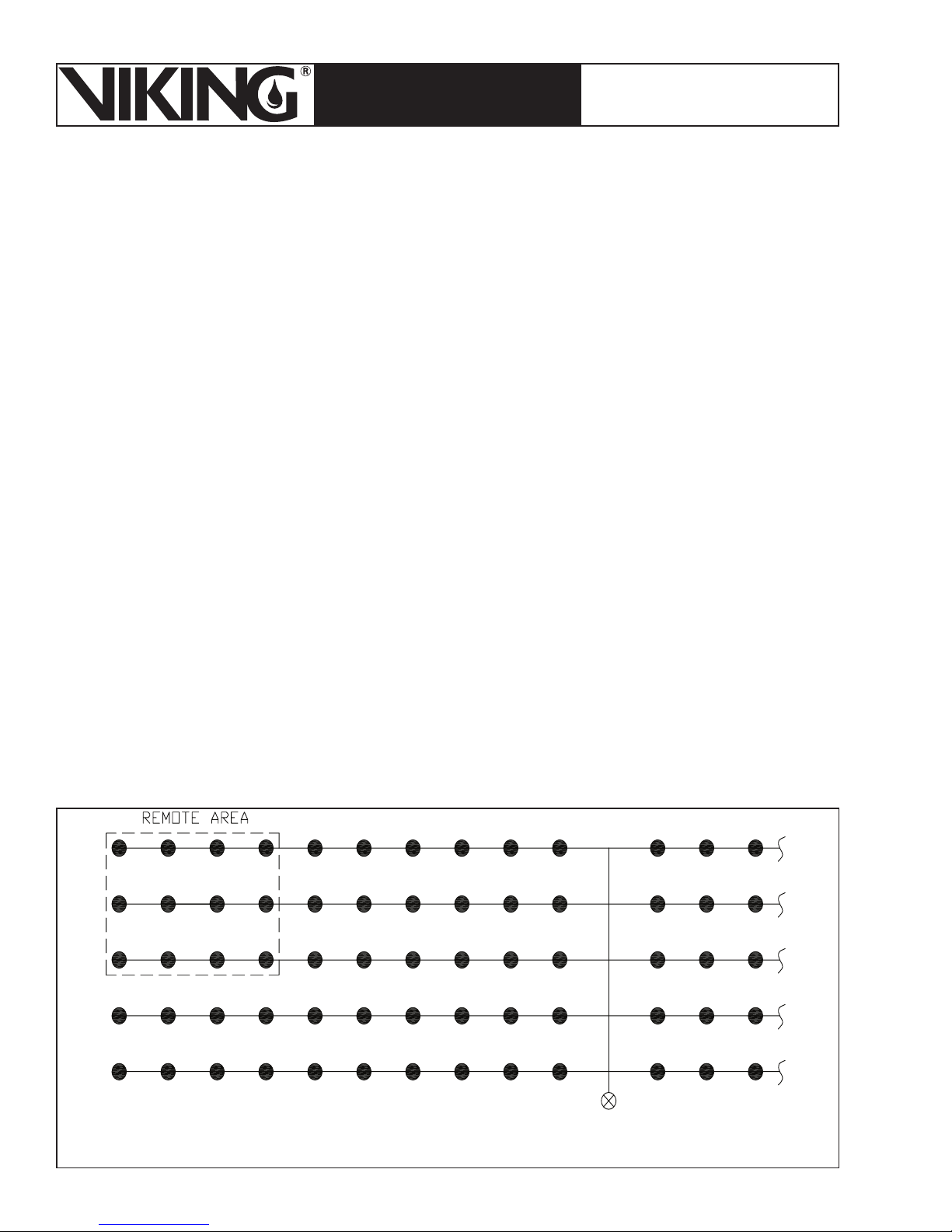
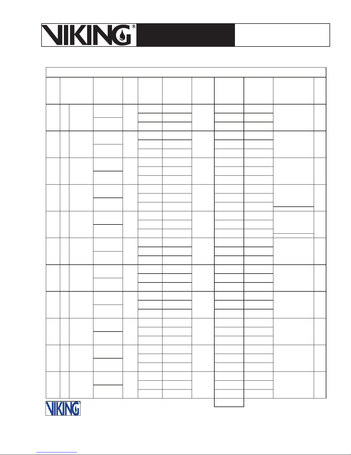
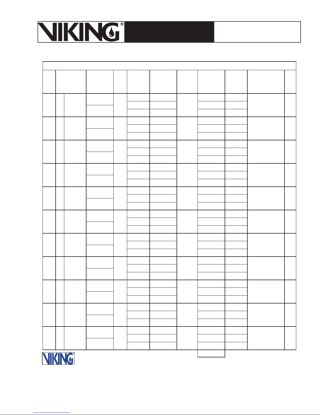
The first calculation shall be with the 12 Viking VK510 K25.2 ESFR’s assuming they are flowing
water. This calculation shall include 4 sprinklers on the 3 most hydraulically remote branch lines
discharging at the minimum design pressure for the system. This calculation shall use the Hazen
Williams formula. See examples in Figures 3 & 4.
The second calculation shall include 6 Viking VK510 K25.2 ESFR’s flowing propylene glycol
solution. The calculation shall include 4 sprinklers on the most hydraulically remote branch line
and 2 sprinklers on the second most hydraulically remote branch line discharging at the minimum
design pressure required for the system. This calculation shall use the Darcy-Weisbach formula.
See examples in Figures 6-8.
Full-scale fire testing has demonstrated that the propylene glycol solution will be expelled from
the system by the time 6 sprinklers are operating in a fire condition. The 6-head sprinkler calculation using the Darcy-Weisbach formula is used to ensure that the piping has been sized properly
and the water supply is adequate for the more viscous liquid. Because the propylene glycol will
have a dramatically different viscosity at the colder temperature expected in this application, friction loss through the piping network will be significantly higher than water.
When conducting hydraulic calculations, a good rule of thumb is to increase pipe size when
friction loss has reached .3 PSI per foot of pipe. By setting up the spreadsheet described in
Appendix B, a quick estimation of the difference in friction loss will assist in determining if the
desired pipe size will be adequate. The final pipe sizes will need to be confirmed through the
actual hydraulic calculations.
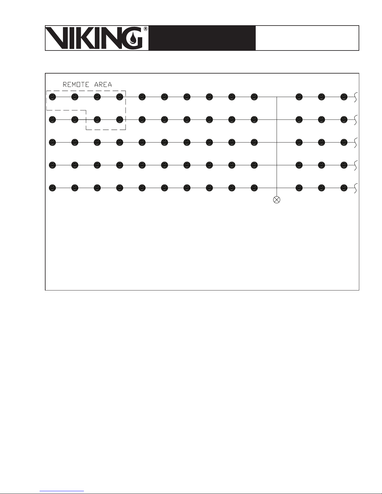
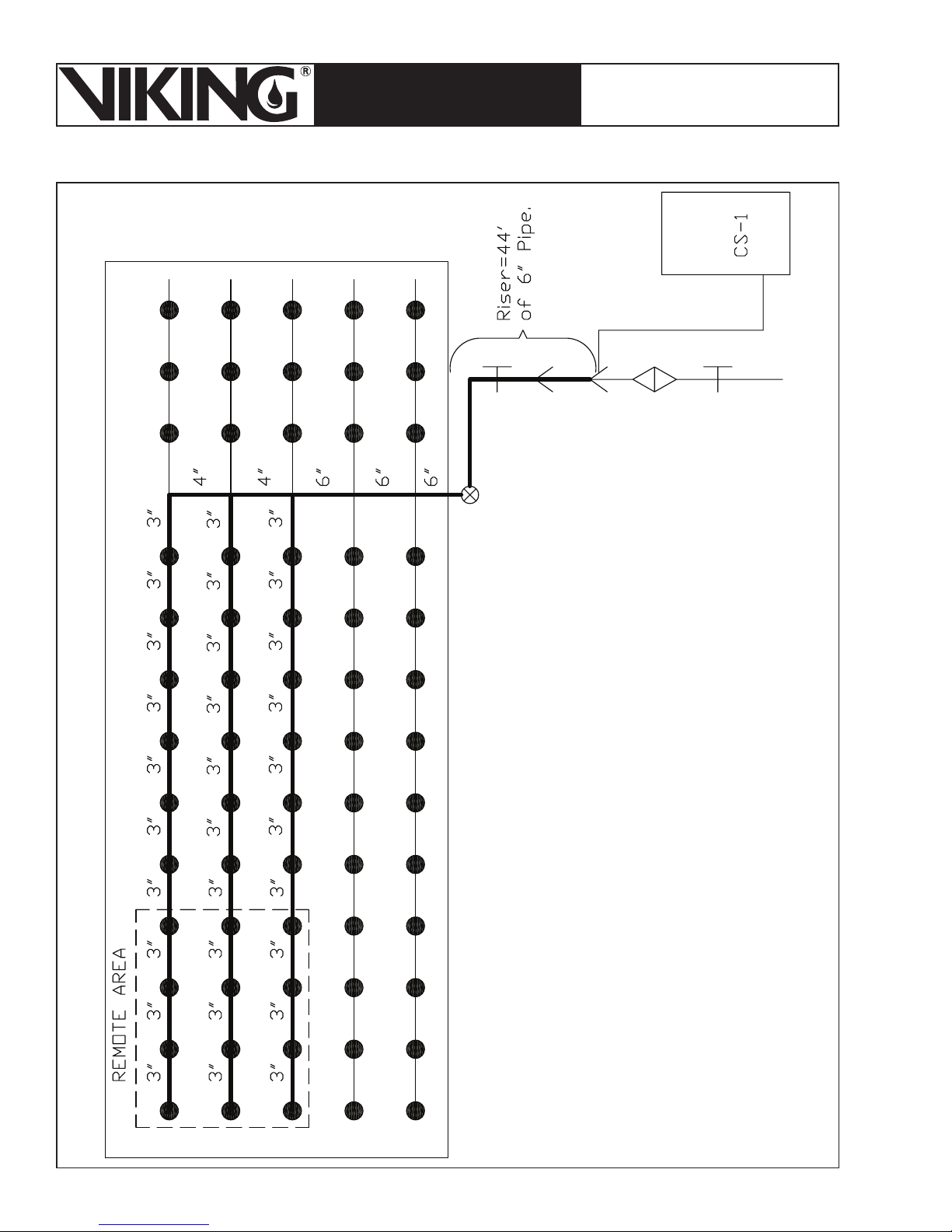
Figure 2 - Example of Remote Area for Hazen Williams Calculation
Center Feed Tree
Page 7
March 7, 2008
ESFR PRE-PRIMED SINGLE
TECHNICAL DATA
INTERLOCK PREACTION
COLD STORAGE SYSTEM
The Viking Corporation, 210 N Industrial Park Road, Hastings MI 49058
Telephone: 269-945-9501 Technical Services 877-384-5464 Fax: 269-945-4495 Email: [email protected]
CONTRACT NAME_ABC Freezer -20 Degrees Class II Commodity____________________________ SHEET__1___OF__2___
Page 7
NOZZLE
IDENT.
AND
LOCATION
STEP NO.
1 Spkr #1
FLOW IN
q
Q 195.2
2 Spkr #2
q 195.6
Q 390.8
3 Spkr # 3
q 197.6
Q 588.4
4 Spkr # 4
q 201.9
Q 790.3
To
5
Bottom of
Riser
Nipple
q
Q 790.3
q
QTPf
6 RN-1
q
Q 790.3
7RN-2
q 794.3
Q 1584.6
8RN-3
q 796.7
Q 2381.3
9
To Top of
Riser
q
Q 2381.3
To
10
Bottom of
Riser
q
Q 2381.3
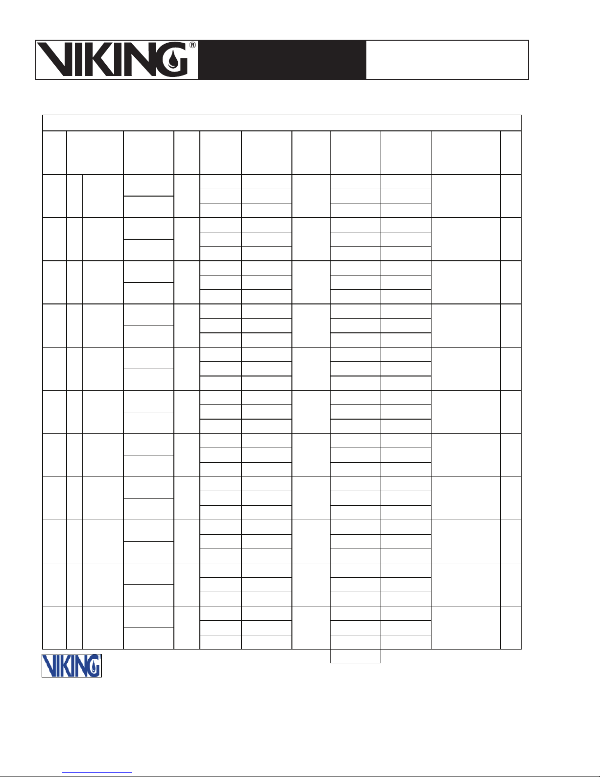
Figure 3 - Hazen Williams Example Calculation of the
25,000 ft.
G.P.M.
PIPE
SIZE
Sch 10
3"
3.26
PIPE
FITTINGS
AND
DEVICES
EQUIV. PIPE
LENGTH
L 10-0
F
T 10-0
FRICTION
LOSS P.S.I./
FOOT
C120
0.03
L 10-0
3"
3.26
F
T 10-0
0.12
L 10-0
3"
3.26
F
T 10-0
0.27
L 31-3
3"
1- Tee F 20
3.29
T 51-3
0.48
L 2-0
3"
1- Tee
3.26
T 22
0.46
L Pt 98.2
FPePv
Sch
10
6"
6.357
L 10-0
F
0.01
L 10-0
6"
6.357
F
0.06
L
6"
6.357
F
1-LTR EL L 154
6"
6.357
1-Tee
F 47
0.13
2- CHK Vl L 37
6"
1- Deluge
6.357
1- Btr Fly T 128
2
Tree System Shown in Figure 9, Sheet 1
F 91
0.13
PRESSURE
SUMMARY
Pt 60 Pt
Pe
Pf .3
Pv
Pn
Pt 60.3 Pt
Pe Pv
Pf 1.2
Pn
Pt 61.5 Pt
Pe
Pv
Pf 2.7 Pn
Pt 64.2 Pt
Pe Pv
Pf 24.6 Pn
Pt 88
PeF 20
Pf 10.2
Pt
Pv
Pn
Pt
Pn
Pt 98.2 Pt
Pe Pv
Pf .1 PnT 10-0
Pt 98.3 Pt
Pe Pv
Pf .6 PnT 10-0
Pt 98.9 Pt
Pe Pv
Pf PnT
Pt 98.9 Pt
Pe Pv
Pf 27.8 PnT 201
Pt 126.7 Pt
Pe 19 Pv
Pf 17.7 Pn
Pt 163.4
NORMAL
PRESSURE
NOTES
Viking K 25.2
Hazen Williams
60
psi Required
Q=K√P
25.2
√60
Q=195.2
√60.3
Q=25.2
Q=195.6
Q=25.2√61.5
Q=197.6
Q=25.2√64.2
Q=201.9
Fitting Adj for
Diameter
15 x 1.34 = 20
Fitting Adj for
Diameter
15 x 1.34 = 20
√P
K=Q/
K=790.3/
√98.2
K=80.12
Q=K√P
Q=80.12
√98.3
Q=794.3
Q=K√P
Q=80.12
√98.9
Q=796.7
Fittings Adj for
Diameter
Elevation 43.75
.433 x 43.75
Fittings Adj for
Diameter
The Viking Corporation
Hastings, Michigan
Litho in U.S.A. Form 3017-HB
REF. STEP
Page 8
Page 8
March 7, 2008
ESFR PRE-PRIMED SINGLE
TECHNICAL DATA
INTERLOCK PREACTION
COLD STORAGE SYSTEM
The Viking Corporation, 210 N Industrial Park Road, Hastings MI 49058
Telephone: 269-945-9501 Technical Services 877-384-5464 Fax: 269-945-4495 Email: [email protected]
CONTRACT NAME__ABC Freezer -20 Degrees Class II Commodity ________________ SHEET__2___OF__2___
NOZZLE
IDENT.
AND
LOCATION
STEP NO.
11
Hose
Stream
12 To Street
FLOW IN
G.P.M.
q 250
Q 2631.3
q
Q 2631.3
q
Q
q
Q
q
Q
q
Q
q
Q
q
Q
q
Q
q
Q
q
Q
PIPE
SIZE
PIPE
FITTINGS
AND
DEVICES
EQUIV. PIPE
LENGTH
FRICTION
LOSS P.S.I./
FOOT
LPt
FPePv
CL-52
1-EL
8"
1 Gt vlv F 67 Pe Pv
8.385
1- Tee
TPfPn
L 100 Pt 163.4
T 167 Pf 4.5 Pn
C 140
0.02
L Pt 168
FPePv
TPfPn
LPt
FPePv
TPfPn
LPt
FPePv
TPfPn
LPt
FPePv
TPfPn
LPt
FPePv
TPfPn
LPt
FPePv
TPfPn
LPt
FPePv
TPfPn
LPt
FPePv
TPfPn
LPt
FPePv
TPfPn
Pt
PRESSURE
SUMMARY
NORMAL
PRESSURE
Pt
Pt
Pt
Pt
Pt
Pt
Pt
Pt
Pt
Pt
Pt
NOTES
48 x 1.33 x 1.05
fittings adj
for C factor
and diameter
ystem Demand
S
gpm
2631
@
168 psi
The Viking Corporation
Hastings, Michigan
Litho in U.S.A. Form 3017-HB
REF. STEP
Figure 4 - Hazen Williams Example Calculation of the
25,000 ft.
2
tree system shown in Figure 9, Sheet 2
Page 9
March 7, 2008
ESFR PRE-PRIMED SINGLE
TECHNICAL DATA
INTERLOCK PREACTION
COLD STORAGE SYSTEM
The Viking Corporation, 210 N Industrial Park Road, Hastings MI 49058
Telephone: 269-945-9501 Technical Services 877-384-5464 Fax: 269-945-4495 Email: [email protected]
Page 9
Typically, when a partial branch line is required in the hydraulic calculations, the sprinklers closer to
the cross main will be used, as shown above. The calculation of the closer sprinklers will result in less
friction loss and a smaller pressure demand on the branch line. At the cross main, a K factor for the
branch lines will need to be determined. The lower pressure requirement will result in a larger K factor and thus require more water on the partial branch line, typically making the closer sprinklers more
demanding.
Figure 5 - Example of Remote Area for Darcy-Weisbach Calculation
Center Feed Tree
Page 10

Page 10
March 7, 2008
ESFR PRE-PRIMED SINGLE
TECHNICAL DATA
INTERLOCK PREACTION
COLD STORAGE SYSTEM
The Viking Corporation, 210 N Industrial Park Road, Hastings MI 49058
Telephone: 269-945-9501 Technical Services 877-384-5464 Fax: 269-945-4495 Email: [email protected]
Darcy-Weisbach Method for Calculating Friction in Piping:
Most hydraulic calculation software used in the sprinkler industry today has the option for conducting
the piping friction loss calculations with the Darcy-Weisbach method. The reason for conducting the
additional 6 sprinkler head calculation is to verify that the available water supply pressure is adequate
for the initial discharge of propylene glycol solution. The example calculations provided in Figures 68 illustrate the difference in results that can occur when calculating for the more viscous propylene
glycol solution versus the standard Hazen-Williams calculation for water illustrated in Figures 3-4.
For those not familiar with the Darcy-Weisbach method below is the basic procedure that is used to
conduct the calculation. This is intended only to provide the designer with an understanding of the
concepts of the method. It is not practical that the calculation be done by hand as this would be much
too time consuming and subject to potential errors.
2
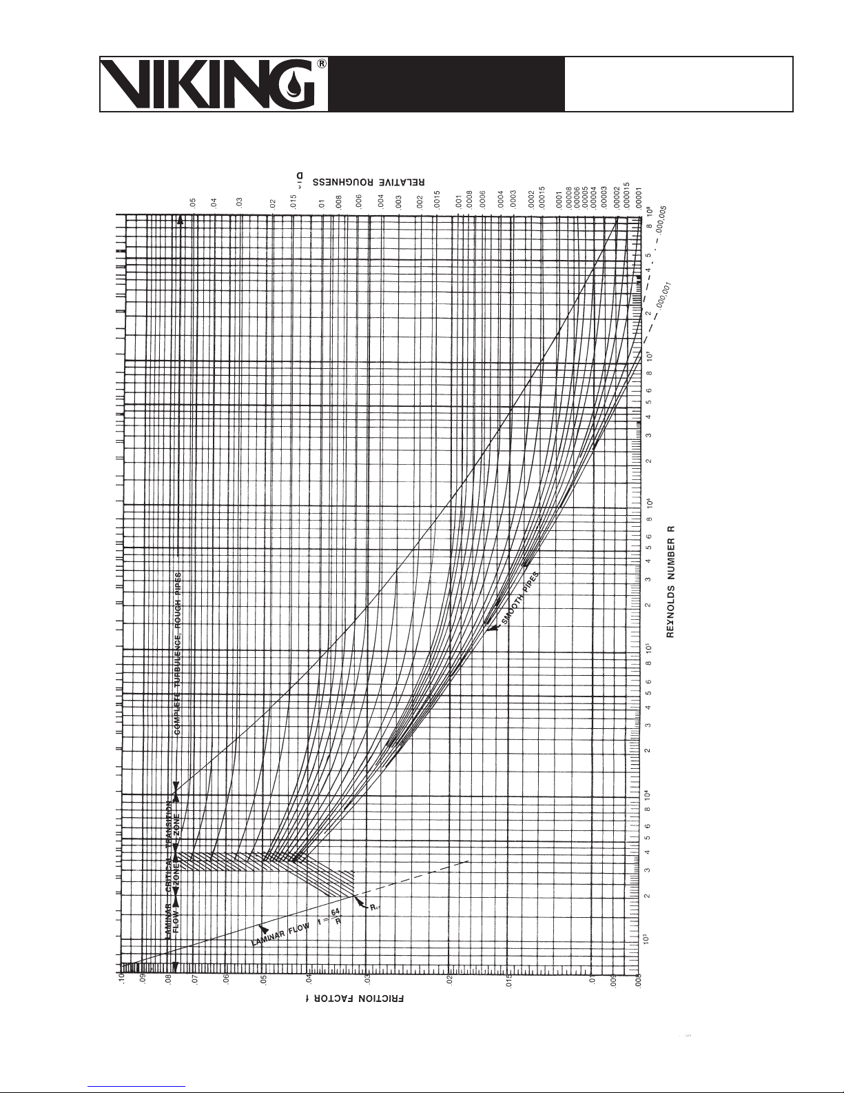
The Darcy-Weisbach Formula as found in most text is written as: h= (f) (l) (v)
h=friction loss (ft of head)
f=friction factor (from Moody Diagram-Figure 10)
l=length of pipe (ft)
v=velocity (ft/sec)
d=diameter of pipe (ft)
2
g=gravitational constant (32.2 ft/sec
)
/ (d) (2) (g)
This formula can be rearranged and simplified to:
2/d5
When the calculated Reynolds Number (Re) is >2000 =0.000216 fLρQ
When the calculated Reynolds Number (Re) is <2000 =0.000273 μLQ/d
=Friction Loss (psi)
4
=Friction Loss (psi)
Where:
Re=50.6Qρ/dμ
Q=flow (gpm)
3
ρ=density (lbs/ft
)
d=internal pipe diameter (in)
D=internal pipe diameter (ft)
L=pipe length (ft)
μ=dynamic viscosity (cps)
ε= .00033 for steel pipe
f=friction factor, If Re > 2000, use Moody Diagram (Figure 10). If Re < 2000, f = 64/Re.
Procedure:
1. Calculate Reynolds Number (Re) = 50.6Qρ/dμ
2. Calculate relative roughness of pipe = ε/D
ε= .00033 (ft)
D=internal pipe diameter (ft)
3. Use Moody Diagram (Figure 10) to find “f” if Re > 2000. If Re < 2000, f = 64/Re.
4. Use fiction loss in hydraulic calculation.
Page 11
March 7, 2008
Page 11
ESFR PRE-PRIMED SINGLE
TECHNICAL DATA
INTERLOCK PREACTION
COLD STORAGE SYSTEM
The Viking Corporation, 210 N Industrial Park Road, Hastings MI 49058
Telephone: 269-945-9501 Technical Services 877-384-5464 Fax: 269-945-4495 Email: [email protected]
CONTRACT NAME_ABC Freezer -20 Degrees Class II Commodity___________________________ SHEET__1___OF__3___
NOZZLE
IDENT.
AND
LOCATION
STEP NO.
1 Spkr #1
2 Spkr #2
3 Spkr #3
4 Spkr #4
To
5
Bottom of
Riser
Nipple
6 RN-1
7 RN-2
8
To Top of
Riser
To
9
Bottom of
Riser
10
Hose
Stream
FLOW IN
G.P.M.
q
Q 195.2
q 196.4
Q 391.6
q 201.2
Q 592.8
q 210.6
Q 803.4
q
Q 803.4
q
Q
q
Q 803.4
q 540
Q 1343.4
q
Q 1343.4
q
Q 1343.4
q 250
Q 1593.4
PIPE
SIZE
Sch 10
3"
3.26
PIPE
FITTINGS
AND
DEVICES
EQUIV. PIPE
LENGTH
L 10-0 Pt 60
FPePv
T 10-0 Pf .8 Pn
FRICTION
LOSS P.S.I./
FOOT
0.08
L 10-0 Pt 60.8
3"
3.26
FPePv
T 10-0 Pf 3.0 Pn
0.3
L 10-0 Pt 63.8
3"
3.26
FPePv
T 10-0 Pf 6.1 Pn
0.61
L 31-3 Pt 69.9
3"
1-Tee F 20 Pe Pv
3.26
T 51-3 Pf 52 Pn
1.03
L 2-0 Pt 121
3"
1-Tee F 20 Pe Pv
3.26
T 22-0 Pf 22.6 Pn
1.03
L Pt 143.6
FPePv
Sch
10
6"
6.357
TPfPn
L 10-0 Pt 143.6
FPePv
T 10-0 Pf .4 Pn
0.04
L Pt 144
6"
6.357
FPePv
TPfPn
1- LTR EL L 154-0 Pt 144
6"
1- Tee F 47-0 Pe Pv
6.357
T 201-0 Pf 21 Pn
0.1
2- Chk Vl L 37 Pt 165
1- Deluge F 91 Pe 19 Pv
1- Btr Fly T 128 Pf 12.8 Pn
0.1
L Pt 196.8
FPePv
TPfPn
Pt 196.8
PRESSURE
SUMMARY
NORMAL
PRESSURE
Pt
Pt
Pt
Pt
Pt
Pt
Pt
Pt
Pt
Pt
Pt
NOTES
Viking K 25.2
y Weisbach
Darc
psi Required
60
Q=K√P
√60
25.2
Q=195.2
Q=25.2√60.8
Q=196.4
Q= 25.2√63.8
Q=201.2
Q=25.2√69.9
Q=210.6
Fitting Adj for
Diameter
15 x 1.34 = 20
Fitting Adj for
Diameter
15 x 1.34 = 20
K=Q/√P
√143.6
K=803.4/
K=67
Q=K√P
√144
Q=45
Q=540
K 45 from
Sheet 3 of 3
Fitting Adj for
Diameter
Elevation 43.7
.433 x 43.75
19
Fittin
Diameter
The Viking Corporation
Hastings, Michigan
Litho in U.S.A. Form 3017-HB
psi
g Adj for
5
REF. STEP
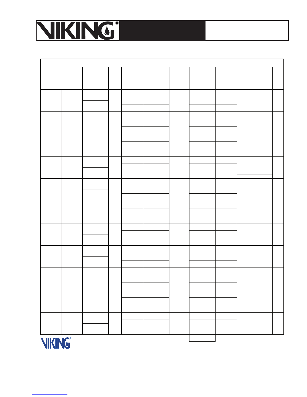
Figure 6 - Darcy-Weisbach Example Calculation of the
25,000 ft.
2
Tree System Shown in Figure 9, Sheet 1
Page 12
Page 12
March 7, 2008
ESFR PRE-PRIMED SINGLE
TECHNICAL DATA
INTERLOCK PREACTION
COLD STORAGE SYSTEM
The Viking Corporation, 210 N Industrial Park Road, Hastings MI 49058
Telephone: 269-945-9501 Technical Services 877-384-5464 Fax: 269-945-4495 Email: [email protected]
CONTRACT NAME_ABC Freezer -20 Degrees Class II Commodity__________________________ SHEET__2___OF__3___
NOZZLE
IDENT.
AND
LOCATION
STEP NO.
11 To Street
FLOW IN
G.P.M.
q
1593.4 1-Tee T
PIPE
SIZE
CL-52
8"
8.385
PIPE
FITTINGS
AND
DEVICES
1-El L 1
1- GT Vl F 67 Pe Pv
q
Q
q
Q
q
Q
q
Q
q
Q
q
Q
q
Q
q
Q
q
Q
q
Q
EQUIV. PIPE
LENGTH
00 Pt 196.8 Pt 48 x 1.33 x 1.05
167 Pf 6.4
LPt 20
FRICTION
LOSS P.S.I./
FOOT
C 140
0.03
PRESSURE
SUMMARY
3.2
NORMAL
PRESSURE
Pn
Pt
NOTES
Fittings Adj
Adj for C Factor
and Diameter
FPePv
TPfPn
LPt
FPePv
TPfPn
LPt
Pt
ystem Demand
S
1593 gpm
@
203 psi
Pt
FPePv
TPfPn
LPt
Pt
FPePv
TPfPn
LPt
Pt
FPePv
TPfPn
LPt
Pt
FPePv
TPfPn
LPt
Pt
FPePv
TPfPn
LPt
Pt
FPePv
TPfPn
LPt
Pt
FPePv
TPfPn
LPt
Pt
FPePv
TPfPn
Pt
The Viking Corporation
Hastings, Michigan
Litho in U.S.A. Form 3017-HB
REF. STEP
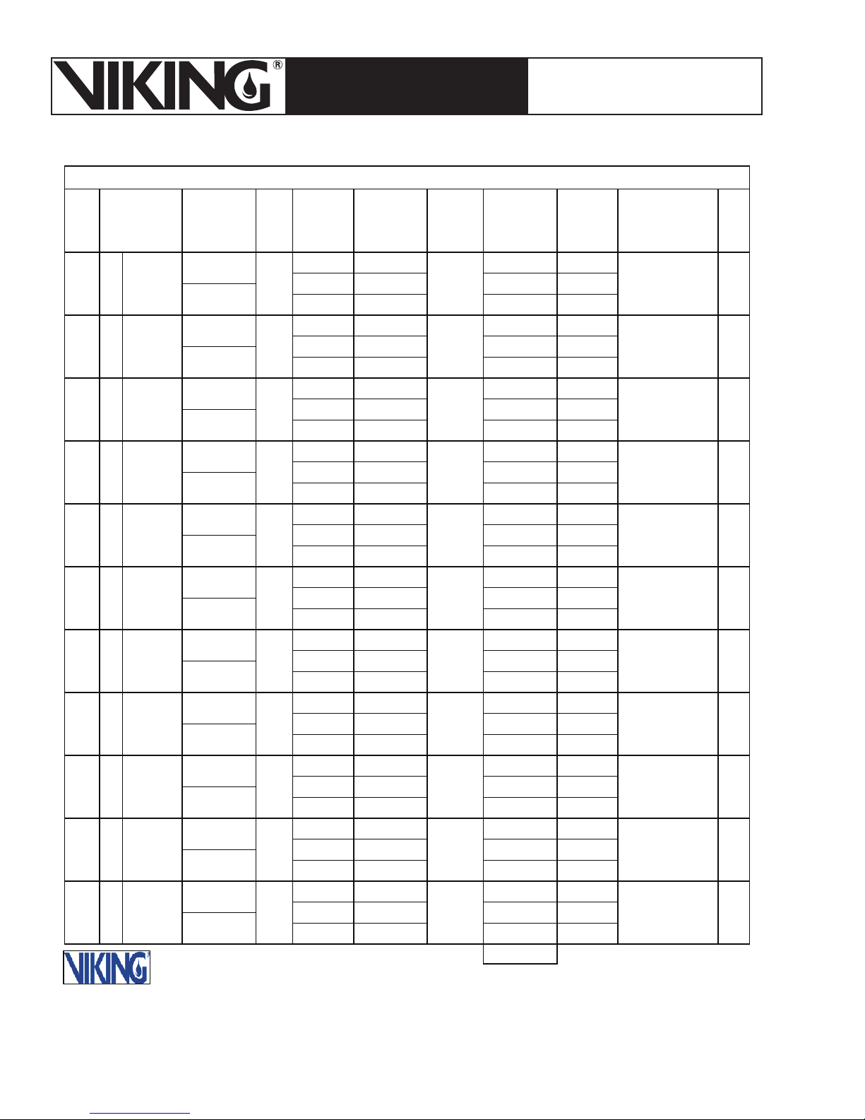
Figure 7 - Darcy-Weisbach Example Calculation of the
2
25,000 ft.
Tree System Shown in Figure 9, Sheet 2
Page 13
March 7, 2008
Page 13
ESFR PRE-PRIMED SINGLE
TECHNICAL DATA
INTERLOCK PREACTION
COLD STORAGE SYSTEM
The Viking Corporation, 210 N Industrial Park Road, Hastings MI 49058
Telephone: 269-945-9501 Technical Services 877-384-5464 Fax: 269-945-4495 Email: [email protected]
CONTRACT NAME__ABC Freezer -20 Degrees Class II Commodity___________________________ SHEET__3___OF__3___
NOZZLE
IDENT.
AND
LOCATION
STEP NO.
12 Spkr #5
13 Spkr#6
FLOW IN
G.P.M.
q
Q 195.2 T 10-0 Pf .8
q 196.4
Q 391.6
PIPE
SIZE
Sch
10
3"
3.26
3"
3.26
PIPE
FITTINGS
AND
DEVICES
1-Tee F 20-0 Pe Pv
q
Q
q
Q
q
Q
q
Q
q
Q
q
Q
q
Q
q
Q
q
EQUIV. PIPE
LENGTH
L 10-0 Pt 60 Pt
FPePv
L 28-9 Pt 60.8
T 48-9 Pf 14.9 Pn
L Pt 75.7
FPePv
TPfPn
LPt
FPePv
TPfPn
LPt
FPePv
TPfPn
LPt
FPePv
TPfPn
LPt
FPePv
TPfPn
LPt
FPePv
TPfPn
LPt
FPePv
TPfPn
LPt
FPePv
TPfPn
LPt
FPePv
QT
FRICTION
LOSS P.S.I./
FOOT
PRESSURE
SUMMARY
0.08
0.3 Diameter
Pf Pn
Pt
NORMAL
PRESSURE
Pn
Pt
Pt
Pt
Pt
Pt
Pt
Pt
Pt
Pt
Pt
NOTES
Q=K√P
Q=25.2√60
Q=195.2
Q=K√P
Q=25.2√60.8
Q=195.2
Fittin
g Adj for
K=
Q/√P
K=391.6/
The Viking Corporation
Hastings, Michigan
Litho in U.S.A. Form 3017-HB
K=45
√75.7
REF. STEP
Figure 8 - Darcy-Weisbach Example Calculation of the
25,000 ft.
2
Tree System Shown in Figure 9, Sheet 3
Page 14
Page 14
March 7, 2008
ESFR PRE-PRIMED SINGLE
TECHNICAL DATA
INTERLOCK PREACTION
COLD STORAGE SYSTEM
The Viking Corporation, 210 N Industrial Park Road, Hastings MI 49058
Telephone: 269-945-9501 Technical Services 877-384-5464 Fax: 269-945-4495 Email: [email protected]
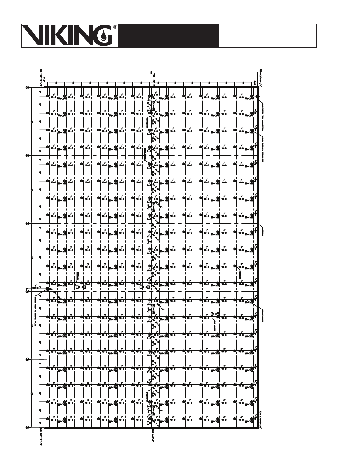
Figure 9 - Plan
View of 25,000
Square Foot
System
Page 15
March 7, 2008
Page 15
ESFR PRE-PRIMED SINGLE
TECHNICAL DATA
INTERLOCK PREACTION
COLD STORAGE SYSTEM
The Viking Corporation, 210 N Industrial Park Road, Hastings MI 49058
Telephone: 269-945-9501 Technical Services 877-384-5464 Fax: 269-945-4495 Email: [email protected]
Figure 10 -
Moody Diagram
Page 16
Page 16
March 7, 2008
ESFR PRE-PRIMED SINGLE
TECHNICAL DATA
INTERLOCK PREACTION
COLD STORAGE SYSTEM
The Viking Corporation, 210 N Industrial Park Road, Hastings MI 49058
Telephone: 269-945-9501 Technical Services 877-384-5464 Fax: 269-945-4495 Email: [email protected]
Figure 11 - Calculating the
Propylene Glycol Volume
Page 17
March 7, 2008
ESFR PRE-PRIMED SINGLE
TECHNICAL DATA
The Viking Corporation, 210 N Industrial Park Road, Hastings MI 49058
Telephone: 269-945-9501 Technical Services 877-384-5464 Fax: 269-945-4495 Email: [email protected]
INTERLOCK PREACTION
COLD STORAGE SYSTEM
Page 17
2. Determining the Required Volume of Propylene Glycol
The system design area (12 sprinklers: 4 on each of the 3 hydraulically most remote branch lines)
and bulk main to the primary Easy Riser® Check Valve (lines in bold) at the base of the riser is
limited to a total volume of 1,100 gallons.* Additional mains and sprinkler lines attached to the
sprinkler system, but not in the direct path to the base of the riser, do not need to be considered
in the volume restriction.
The actual volume of propylene glycol solution for the sprinkler system is determined by adding
all the sprinkler piping together. Additional propylene glycol is added to this total for the CS-1
Tank and supply lines to the riser.
Table 1
From NFPA 13 - Table A.7.2.3 -
Capacity of 1 ft. of Pipe (Based on Actual Internal Pipe Diameter)
Nominal
Pipe
Pipe
Diameter
in. mm
Schedule 40
(gal)
Schedule 10
(gal)
3/4 20 0.028 - 3 80 0.383 0.433
1 25 0.045 0.049 3½ 90 0.513 0.576
1¼ 32 0.078 0.085 4 100 0.660 0.740
1½ 40 0.106 0.115 5 125 1.040 1.144
2 50 0.174 0.190 6 150 1.501 1.649
2½ 65 0.248 0.283 8 200 2.66
For SI units, 1 in. = 25.4 mm; 1 ft. = 0.3048 m; 1 gal = 3.785 L.
a
Schedule 80.
b
0.134 wall pipe.
c
0.188 wall pipe.
Nominal
Pipe
Diameter
in. mm
Pipe
Schedule 40
(gal)
a
Schedule 10
(gal)
b
c
2.776
Example:
Assume 100 ft² spacing, 10 ft between the sprinklers and 10 ft between the branch lines.
•
Schedule 10 Pipe.
•
3” Pipe = 300’ x .433 = 129.9 gal.
4” Pipe = 20’ x .740 = 14.8 gal.
6” Pipe = 74’ x 1.649 = 120.0 gal.
Total Volume = 247 gal.
* Note: Based on the installation history of this system, systems near 25,000 ft2 in area, with long runs on feed main, typically
begin to approach the 1,100 gallon restriction, or begin to demand excessive pressures in the Darcy-Weisbach calculation.
This history can be used as an estimating tool, however, the actual system volume must be calculated.
Page 18
Page 18
ESFR PRE-PRIMED SINGLE
TECHNICAL DATA
The Viking Corporation, 210 N Industrial Park Road, Hastings MI 49058
Telephone: 269-945-9501 Technical Services 877-384-5464 Fax: 269-945-4495 Email: [email protected]
INTERLOCK PREACTION
COLD STORAGE SYSTEM
March 7, 2008
3. Typical Storage Arrangements
Definitions:
Class II Commodity - A Class II commodity shall be defined as a noncombustible product that
is in slatted wooden crates, solid wood boxes, multiple layered corrugated cartons or equivalent
combustible packaging material with or without pallets.
Longitudinal Flue Space - The space between the rows of storage perpendicular to the direction of loading.
Transverse Flue Space - The distance between rows of storage parallel to the direction of loading.
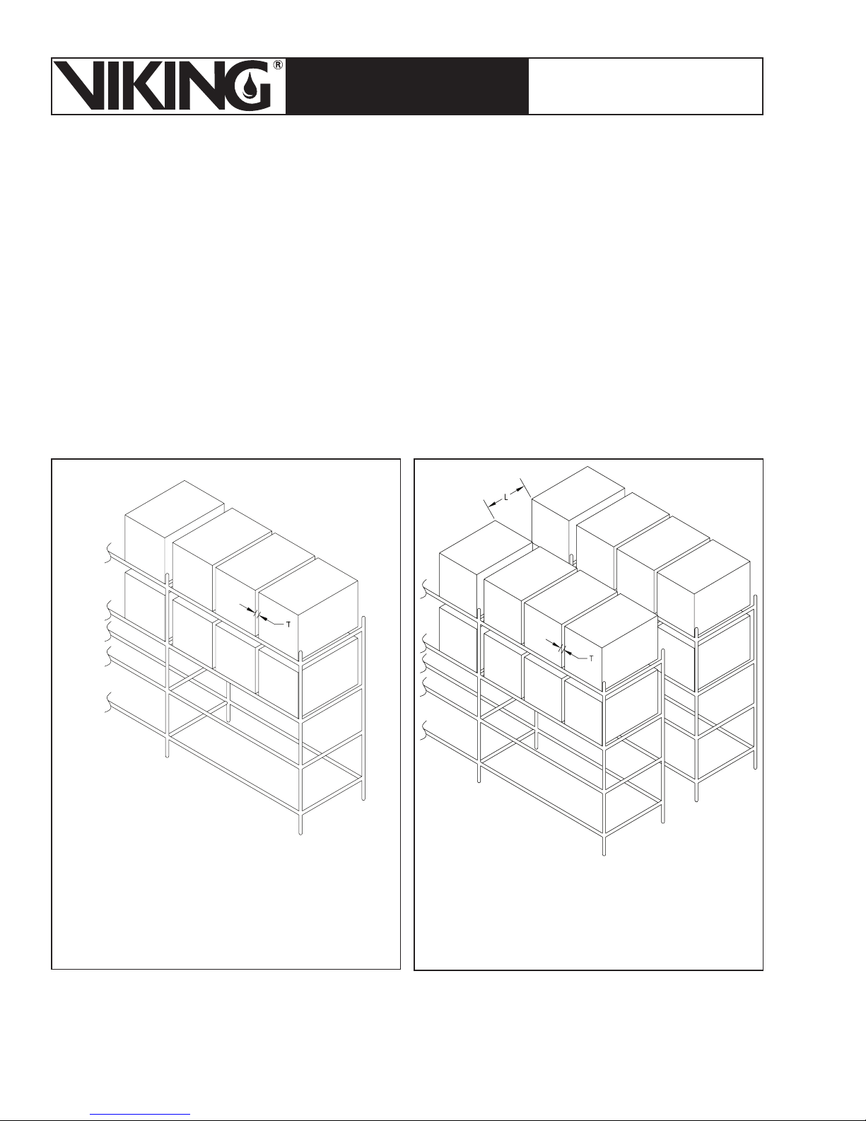
L = Longitudinal Flue Space
T = Transverse Flue Space
Figure 12 - Single Row Rack Storage
Racks that have no longitudinal fl ue space
and that have width up to 6 ft, and aisles at
leas 3½ ft from any other storage.
Figure 13 - Double Row Rack Storage
Two single row racks placed back to back
having a combined width up to 12 ft with
aisles at least 3½ ft on each side.
Page 19

March 7, 2008
ESFR PRE-PRIMED SINGLE
TECHNICAL DATA
The Viking Corporation, 210 N Industrial Park Road, Hastings MI 49058
Telephone: 269-945-9501 Technical Services 877-384-5464 Fax: 269-945-4495 Email: [email protected]
INTERLOCK PREACTION
COLD STORAGE SYSTEM
Page 19
Figure 14 - Multiple Row Rack
Storage
Racks greater than 12 ft (3.7 m) wide or single or double row racks separated by aisles less
than 3½ ft (1.07 mm) wide having an overall width greater than 12 ft (3.7 m).
Notes:
The system is acceptable for use with Class I and Class II commodities only.
1.
For use with a maximum 50% by volume propylene glycol and water antifreeze solution with
2.
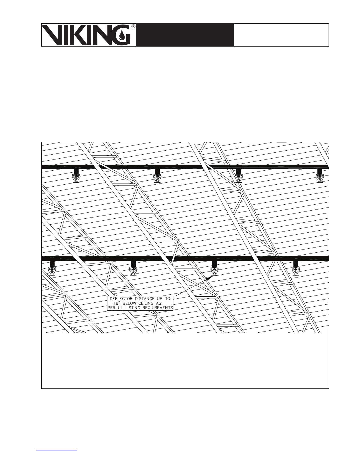
a maximum ceiling height of 40 ft (12.2 m) and a maximum Class II commodity height of 35 ft
(10.7 m) with a maximum deflector distance below the ceiling of 18” (457 mm). The minimum
starting pressure is 40 PSI (2.76 Bar).
For use with a maximum 50% by volume propylene glycol and water antifreeze solution with
3.
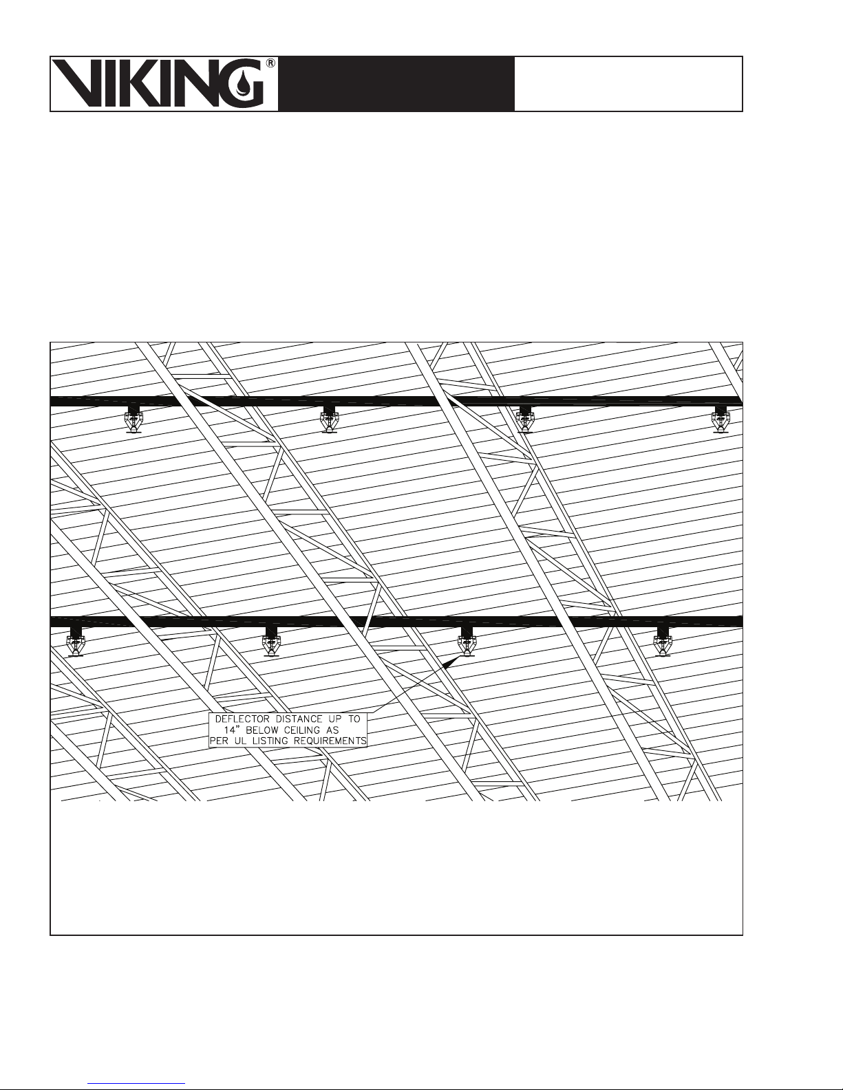
a maximum ceiling height of 45ft-3 in (13.8 m) and a maximum Class II commodity height
of 40 ft (12.2 m) with a maximum deflector distance below the ceiling of 14” (356 mm). The
minimum starting pressure is 60 PSI (4.14 Bar).
The VK510 ESFR’s shall be ordinary temperature 165 °F (74 °C) except where required to
4.
be intermediate temperature 205 °F (96 °C) due to close proximity to heating sources as
described in NFPA 13.
The system shall be designed so that the maximum operating pressure does not exceed 175
5.
PSI (12 Bar) at the ESFR sprinklers.
Only wood pallets are acceptable.
6.
Page 20
Page 20
March 7, 2008
ESFR PRE-PRIMED SINGLE
TECHNICAL DATA
INTERLOCK PREACTION
COLD STORAGE SYSTEM
The Viking Corporation, 210 N Industrial Park Road, Hastings MI 49058
Telephone: 269-945-9501 Technical Services 877-384-5464 Fax: 269-945-4495 Email: [email protected]
Figure 15 - Maximum ceiling height of 45 ft-3 in and a maximum height
of 40 ft with a maximum deflector distance below the ceiling of 14”
Page 21
March 7, 2008
Page 21
ESFR PRE-PRIMED SINGLE
TECHNICAL DATA
INTERLOCK PREACTION
COLD STORAGE SYSTEM
The Viking Corporation, 210 N Industrial Park Road, Hastings MI 49058
Telephone: 269-945-9501 Technical Services 877-384-5464 Fax: 269-945-4495 Email: [email protected]
Figure 16 - Maximum ceiling height of 40 ft and commodity height of
35 ft with a maximum deflector distance below the ceiling of 18”
Page 22

Page 22
March 7, 2008
ESFR PRE-PRIMED SINGLE
TECHNICAL DATA
INTERLOCK PREACTION
COLD STORAGE SYSTEM
The Viking Corporation, 210 N Industrial Park Road, Hastings MI 49058
Telephone: 269-945-9501 Technical Services 877-384-5464 Fax: 269-945-4495 Email: [email protected]
Table 2 - NFPA 13 Table A5.6.3.1, 2007 Edition
Table A.5.6.3.1 Examples of Class I Commodities Table A.5.6.3.1 Continued
Alcoholic Beverages
Cartoned or uncartoned
- Up to 20 percent alcohol in metal, glass, or ceramic containers
Appliances, Major (e.g., stoves, refrigerators)
- Not packaged, no appreciable plastic exterior
trim
Batteries
Dry cells (nonlithium or similar exotic metals)
- Packaged in cartons
Automobile
- Filled*
Bottles, Jars
Empty, cartoned
- Glass
Filled noncombustible liquids
- Glass, cartoned
- Plastic, cartoned [less than 5 gal (18.9 L)]
- Plastic, PET
Filled noncombustible powders
- Glass, cartoned
Canned Foods
In ordinary cartons
Cans
Metal
- Empty
Cement
Bagged
Coffee
Canned, cartoned
Fertilizers
Bagged
- Phosphates
File Cabinets
Metal
- Cardboard box or shroud
Fish or Fish Products
Frozen
- Nonwaxed, nonplastic packaging
Canned
- Cartoned
Frozen Foods
Nonwaxed, nonplastic packaging
Fruit
Fresh
- Nonplastic trays or containers
-With wood spacers
Ice Cream
Meat, Meat Products
- Bulk
- Canned, cartoned
- Frozen, nonwaxed, nonplastic containers
Metal Desks
-With plastic tops and trim
Milk
- Nonwaxed-paper containers
- Waxed-paper containers
- Plastic containers
Motors
- Electric
Nuts
- Canned, cartoned
Paints
Friction-top cans, cartoned
- Water-based (latex)
Plastic Containers
- Noncombustible liquids or semiliquids in plastic containers less than 5 gal (18.9 L) capacity
Poultry Products
- Canned, cartoned
- Frozen, nonwaxed, nonplastic containers
Salt
Bagged
Syrup
Drummed (metal containers)
Transformers
Dry and oil fi lled
Wire
Bare wire on metal spools on wood skids
*Most batteries have a polypropylene case and,
if stored empty, should be treated as a Group A
plastic. Truck batteries, even where fi lled, should
be considered a Group A plastic because of their
thicker walls.
Page 23

March 7, 2008
Page 23
ESFR PRE-PRIMED SINGLE
TECHNICAL DATA
INTERLOCK PREACTION
COLD STORAGE SYSTEM
The Viking Corporation, 210 N Industrial Park Road, Hastings MI 49058
Telephone: 269-945-9501 Technical Services 877-384-5464 Fax: 269-945-4495 Email: [email protected]
Table 3 - NFPA 13 Table A.5.6.3.2, 2007 Edition
Table A.5.6.3.2 Examples of Class II Commodities Table A.5.6.3.2 Continued
Alcoholic Beverages
Up to 20 percent alcohol in wood containers
Appliances, Major (e.g., stoves)
Corrugated, cartoned (no appreciable plastic trim)
Baked Goods
Cookies, cakes, pies
- Frozen, packaged in cartons*
Batteries
Dry cells (nonlithium or similar exotic metals) in
blister pack in cartons
Bottles, Jars
Filled noncombustible powders
- Plastic PET
Boxes, Crates
Empty, wood, solid walls
Fertilizers
Bagged
- Nitrates
Fish or Fish Products
Frozen
- Waxed-paper containers, cartoned
- Boxed or barreled
Frozen Foods
Waxed-paper containers, cartoned
Leather Hides
Baled
Light Fixtures
Nonplastic
- Cartoned
Marble
Artifi cial sinks, countertops
- Cartoned, crated
Meat, Meat Products
- Frozen, waxed-paper containers
- Frozen, expanded plastic trays
Pharmaceuticals
Pills, powders
- Glass bottles, cartoned
Nonfl ammable liquids
- Glass bottles, cartoned
Photographic Film
- Motion picture or bulk rolls of fi lm in polycarbon-
ate, polyethylene, or metal cans; polyethylene
bagged in cardboard boxes
Plastic Containers
Noncombustible liquids or semiliquids (such as
ketchup) in plastic containers with nominal wall
thickness of L/4 in. (6.4 mm) or less and larger
than 5 gal (18.9 L) capacity
Poultry Products
Frozen (on paper or expanded plastic trays)
Powders (ordinary combustibles - free fl owing)
In paper bags (e.g., fl our, sugar)
Salt
Packaged, cartoned
Shock Absorbers
Metal dust cover
Signatures
Book, magazines
- Solid array on pallet
Syrup
Barreled, wood
Wire
- Bare wire on wood or cardboard spools on
wood skids
- Bare wire on metal, wood, or cardboard spools
in cardboard boxes on wood skids
- Single- or multiple-layer PVC-covered wire on
metal spools on wood skids
- Insulated (PVC) cable on large wood or metal
spools on wood skids
Wood Products
Solid piles
- Lumber, plywood, particle board, pressboard
(smooth ends and edges)
*The product is in a plastic-coated package in a
corrugated carton. If packaged in a metal foil, it can
be considered Class I.
Page 24
Page 24
March 7, 2008
ESFR PRE-PRIMED SINGLE
TECHNICAL DATA
INTERLOCK PREACTION
COLD STORAGE SYSTEM
The Viking Corporation, 210 N Industrial Park Road, Hastings MI 49058
Telephone: 269-945-9501 Technical Services 877-384-5464 Fax: 269-945-4495 Email: [email protected]
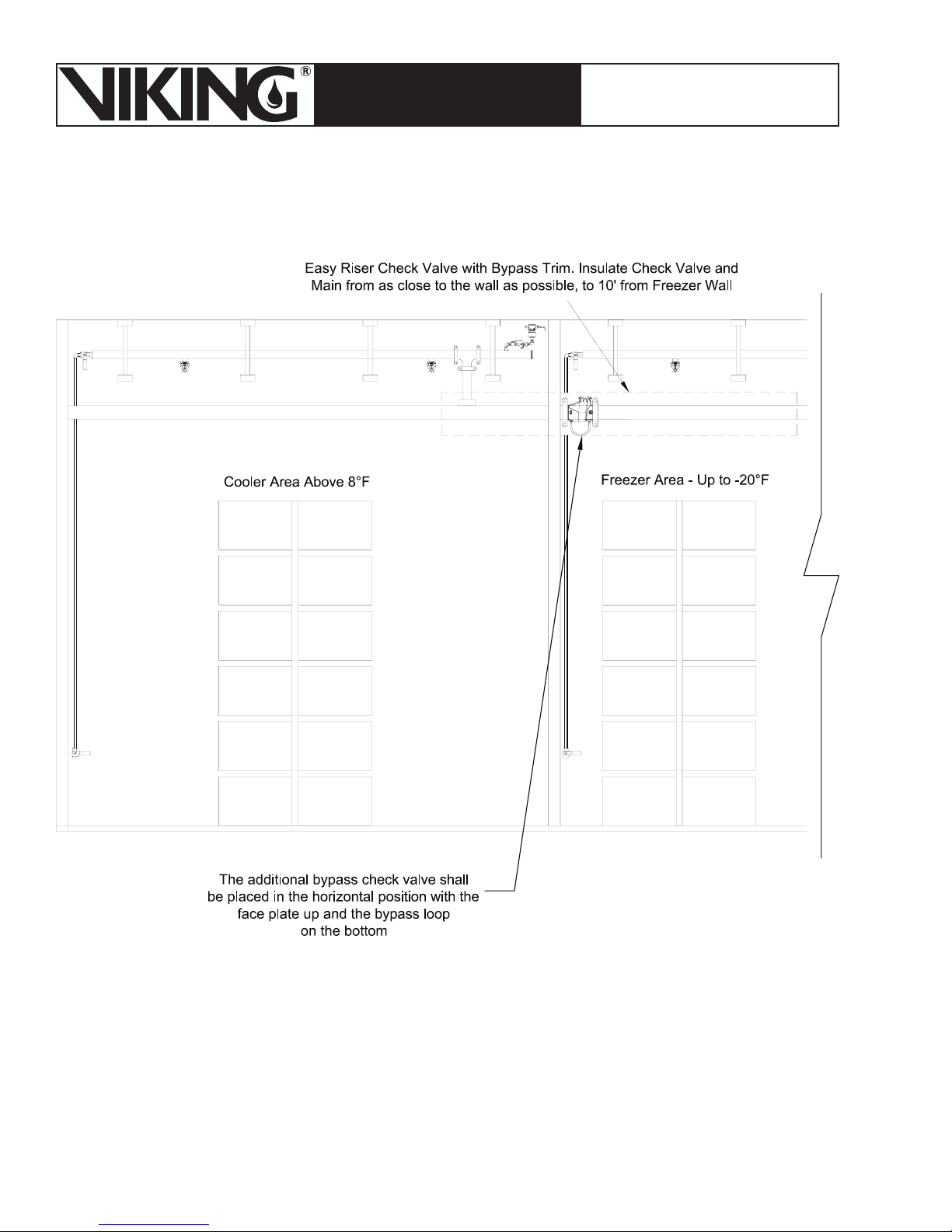
Figure 17 - Adjacent Freezer and Cooler
Where the building has separate cooler and freezer areas, it will be necessary to install additional
bypass check valves to prevent thermal transfer and frosting from one area to another.
Page 25

March 7, 2008
Page 25
ESFR PRE-PRIMED SINGLE
TECHNICAL DATA
INTERLOCK PREACTION
COLD STORAGE SYSTEM
The Viking Corporation, 210 N Industrial Park Road, Hastings MI 49058
Telephone: 269-945-9501 Technical Services 877-384-5464 Fax: 269-945-4495 Email: [email protected]
Page 26

Page 26
ESFR PRE-PRIMED SINGLE
TECHNICAL DATA
The Viking Corporation, 210 N Industrial Park Road, Hastings MI 49058
Telephone: 269-945-9501 Technical Services 877-384-5464 Fax: 269-945-4495 Email: [email protected]
INTERLOCK PREACTION
COLD STORAGE SYSTEM
March 7, 2008
4. Designing the Detection System
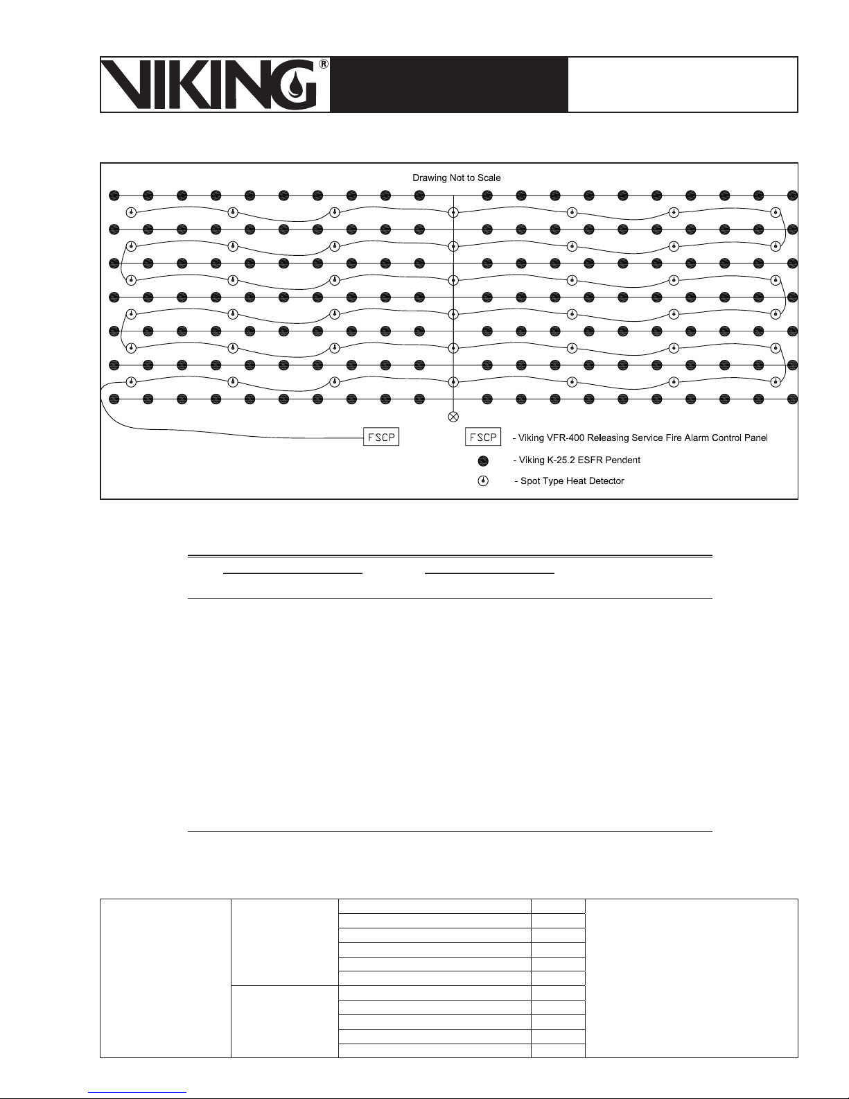
The detection system shall consist of low temperature “spot” type heat detectors, air sampling
smoke detection or beam smoke detection. Linear heat detection is not suitable for this system
and shall not be used.
Viking does not have a preferred manufacturer of initiating devices. Spot heat detectors are
typically not subject to compatibility issues with the release control panel. Viking considers all
listed and approved spot type heat detectors that the manufacturer determines is appropriate for
cold storage applications acceptable. The detection system shall be designed to allow the heat
detectors to operate prior to the Viking K25.2 ESFR sprinklers by selecting a lower temperature
rating and RTI for the heat detector. (NFPA 13 defines an ESFR Sprinkler as having a thermal
element with an RTI of 50 (meters sec.½) or less.) The heat detector manufacturer shall be contacted for the heat detector RTI information.
Air sampling systems are also considered acceptable for activation of the ESFR Cold Storage
System, and should be designed in accordance with the manufacturer’s instructions.
The detection system shall be designed in accordance with the requirements of NFPA 72.
5.6.2.3 Marking: Heat-sensing fire detectors shall be marked with their listed operating temperature. Spot-type heat detectors shall also be marked with their RTI (response time index). The
RTI marking requirements shall have an effective date of July 1, 2008.
5.6.5.5.1 On ceilings 10 ft to 30 ft (3 m to 9.1 m) high, heat detector linear spacing shall be
reduced in accordance with Table 5.6.5.5.1 prior to any additional reductions for beams, joists,
or slope, where applicable.
5.6.5.5.2 The minimum spacing of heat detectors shall not be required to be less than 0.4 times
the height of the ceiling.
Table 4 - Detector Classification from NFPA 72
Table 5.6.2.1.1 Temperature Classifi cation for Heat-Sensing Fire Detectors
Temperature
Classifi cation
Low* 100-134 39-57 80 28 Uncolored
Ordinary 135-174 58-79 115 47 Uncolored
Intermediate 175-249 80-121 155 69 White
High 250-324 122-162 230 111 Blue
Extra high 325-399 163-204 305 152 Red
Very extra high 400-499 205-259 380 194 Green
Ultra high 500-575 260-302 480 249 Orange
*Intended only for installation in controlled ambient areas. Units shall be marked to indicate maximum ambient installation
temperature.
Temperature Rating Range Maximum Ceiling Temperature Color
° F ° C ° F ° C
Code
Page 27
March 7, 2008
Page 27
ESFR PRE-PRIMED SINGLE
TECHNICAL DATA
INTERLOCK PREACTION
COLD STORAGE SYSTEM
The Viking Corporation, 210 N Industrial Park Road, Hastings MI 49058
Telephone: 269-945-9501 Technical Services 877-384-5464 Fax: 269-945-4495 Email: [email protected]
Figure 18 - Detection System
Table 5 - Spacing Reductions from NFPA 72
Table 5.6.5.5.1 Heat Detector Spacing Reduction Based on Ceiling Height
Ceiling Height Above Up to and Including Multiply Listed
mftmft
Spacing by
0 0 3.05 10 1.00
3.05 10 3.66 12 0.91
3.66 12 4.27 14 0.84
4.27 14 4.88 16 0.77
4.88 16 5.49 18 0.71
5.49 18 6.10 20 0.64
6.10 20 6.71 22 0.58
6.71 22 7.32 24 0.52
7.32 24 7.93 26 0.46
7.93 26 8.54 28 0.40
8.54 28 9.14 30 0.34
III. INSTALLATION AND COMPONENT FUNCTIONS
Note: All materials installed on the system shall be compatible with the propylene glycol solution.
PVC C
CPVC C
Table 6 -
Propylene
Glycol
Compatibility
Chart
Thermoplastics
Gaskets
Polyethylene (PE) B
Polyethylene Cross Linked (XLPE) A
Teflon A
ABS B
Viton A
EPDM A
Neoprene C
Buna N (Nitrile) A
Hypalon A
A = Excellent resistance
B = Fair
C = Poor
Information provided by The Noble
Company
Page 28
Page 28
ESFR PRE-PRIMED SINGLE
TECHNICAL DATA
The Viking Corporation, 210 N Industrial Park Road, Hastings MI 49058
Telephone: 269-945-9501 Technical Services 877-384-5464 Fax: 269-945-4495 Email: [email protected]
INTERLOCK PREACTION
COLD STORAGE SYSTEM
March 7, 2008
1. Water Supply Control Valve
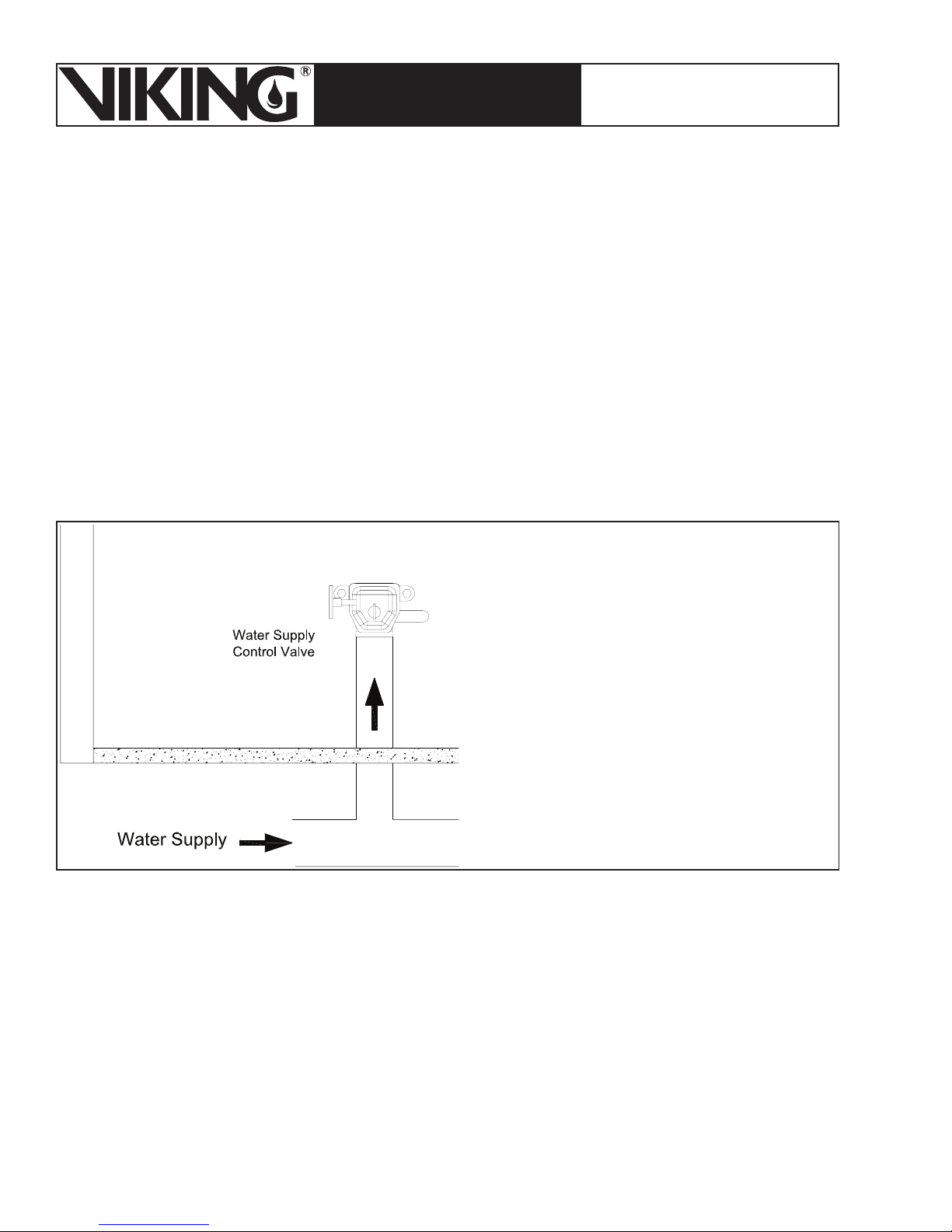
A listed indicating valve shall be installed on the upstream side of the deluge valve. The valve
shall not close in less than 5 seconds when operated at maximum possible speed from the fully
opened position. Valves shall conform to the requirements of NFPA 13 (8.16.1.1.2 2007 ed.):
8.16.1.1.2* Supervision.
8.16.1.1.2.1 Valves on connections to water supplies, sectional control and isolation valves, and
other valves in supply pipes to sprinklers and other fixed water-based fire suppression systems
shall be supervised by one of the following methods:
Central station, proprietary, or remote station signaling service
1)
Local signaling service that will cause the sounding of an audible signal at a constantly at-
2)
tended point
Valves locked in the correct position
3)
Valves located within fenced enclosures under the control of the owner, sealed in the open
4)
position, and inspected weekly as part of an approved procedure
Figure 19 - Water
Supply Control Valve
2. Grooved Couplings
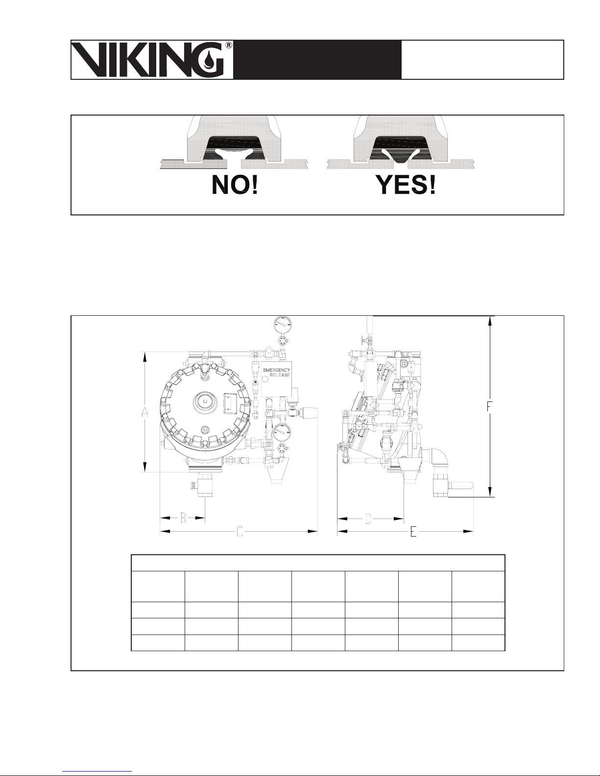
In order to prevent leaks and preserve the antifreeze solution, it is imperative that grooved pipe
ends are smooth, round, and free of burrs, flat spots, and weld seam imperfections. Also, pipes
should be capped to prevent contaminant during shipping, storage, etc. Verify that any gasket
materials used in couplings, etc. are compatible with the antifreeze solution. Refer to the antifreeze solution technical data page.
Where grooved couplings are used in the system, “flush seal” gasket, low temperature EPDM
rubber and lube are required. Gaskets: grade “E” EPDM, NSF-61 Certified, -40 °F to 230 °F (service temperature range) (-40 °F to 110 °F) recommended for water service, diluted acids, alkalys
solutions, oil-free air and many chemical services. GRUVLOK Xtrema Lubricant is required for
freezer applications. In order to pervent leaks and preserve the antifreeze solution, the grooved
pipe ends must be smooth, round, and free of burrs.
Page 29
March 7, 2008
ESFR PRE-PRIMED SINGLE
TECHNICAL DATA
The Viking Corporation, 210 N Industrial Park Road, Hastings MI 49058
Telephone: 269-945-9501 Technical Services 877-384-5464 Fax: 269-945-4495 Email: [email protected]
INTERLOCK PREACTION
COLD STORAGE SYSTEM
Page 29
Figure 20 - Grooved Couplings
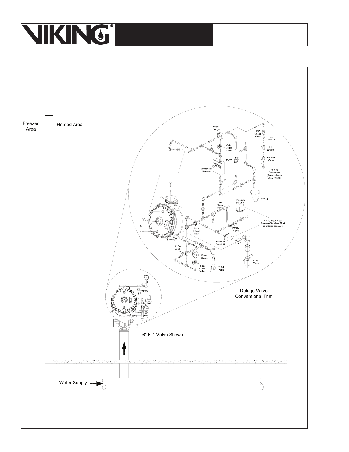
3. Deluge Valve with Conventional Trim
The ESFR Cold Storage System utilizes a Viking Model F-1 Deluge Valve. Refer to Viking
Technical data pages for Valve Specifications.
The Deluge V alve is to be installed using Deluge Valve Conventional Trim. Refer to the trim drawing on the following page for details.
Valve
Size
4” 19-1/2 7-1/4 28-1/2 13 22-7/16 34-5/8
6” 24-5/16 9-1/8 31-7/8 13-7/16 27-1/2 36-5/8
8” 29-1/2 11-1/4 35-5/16 14-1/4 19-7/8 39-1/4
Figure 21 - Valve and Trim Dimensions
ABCDEF
Page 30
Page 30
March 7, 2008
ESFR PRE-PRIMED SINGLE
TECHNICAL DATA
INTERLOCK PREACTION
COLD STORAGE SYSTEM
The Viking Corporation, 210 N Industrial Park Road, Hastings MI 49058
Telephone: 269-945-9501 Technical Services 877-384-5464 Fax: 269-945-4495 Email: [email protected]
Figure 22 - Deluge Valve and Trim
Page 31
March 7, 2008
Page 31
ESFR PRE-PRIMED SINGLE
TECHNICAL DATA
INTERLOCK PREACTION
COLD STORAGE SYSTEM
The Viking Corporation, 210 N Industrial Park Road, Hastings MI 49058
Telephone: 269-945-9501 Technical Services 877-384-5464 Fax: 269-945-4495 Email: [email protected]
NOTES: An alarm test connection is provided on the deluge valve trim. When testing the alarm,
the downstream isolation valve (illustrated in Figure 30) and antifreeze isolation valve (illustrated in Figure 33) must be shut before opening the test valve.
This is a precaution in case the deluge valve would inadvertently operate due to problems in
the trim components and cause water to enter the system causing possible contamination of
antifreeze. After testing of the alarm, restore the control valves to their normal operating position and open the antifreeze supply valve.
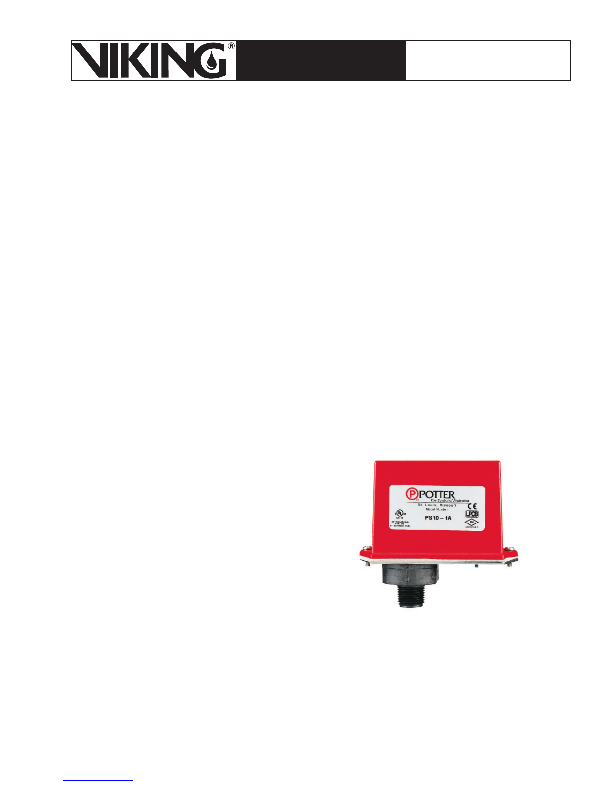
A. Water Flow Pressure Switches (PS-10)
Each system requires 2 water flow pressure switches that transmit an alarm after the system
has activated.
The Double Switch (PS-10-2A) Water Flow Pressure Switch (Switch #1) is installed on the
deluge valve conventional trim. In addition to transmitting an alarm signal, Switch #1 is wired
in conjunction with digital Switch #5 to prevent the solenoid valve on the CS-1 Tank and Pump
Unit from opening when the water flow switch is activated. This prevents propylene glycol from
entering the system when water is flowing.
The Single Switch (PS-10-1A) Water Flow Pressure Switch (Switch #2) is installed on the deluge valve conventional trim. Switch #2 is wired in conjunction with Digital Pressure Switch #4
in order to prevent the operation of the APCS during system operation.
Page 32
Page 32
March 7, 2008
ESFR PRE-PRIMED SINGLE
TECHNICAL DATA
INTERLOCK PREACTION
COLD STORAGE SYSTEM
The Viking Corporation, 210 N Industrial Park Road, Hastings MI 49058
Telephone: 269-945-9501 Technical Services 877-384-5464 Fax: 269-945-4495 Email: [email protected]
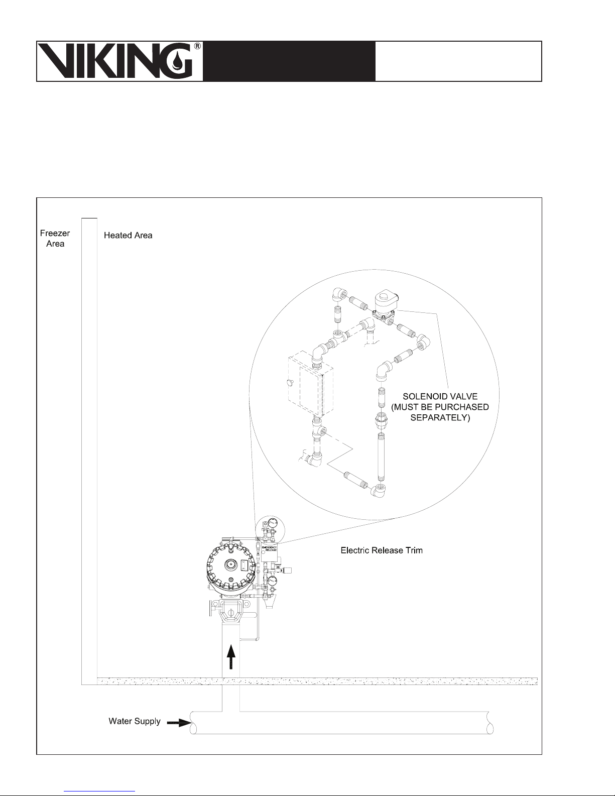
4. Electric Release Trim
A standard Deluge Electric Release Trim Package is required to be installed onto the Deluge
Conventional Trim. The Electric Release Trim Package includes all of the necessary pipe and
fittings to install the release solenoid to the Valve Trim. The Solenoid Valve is NOT included and
must be ordered separately.
Figure 23 - Electric Release Trim
Page 33
March 7, 2008
Page 33
ESFR PRE-PRIMED SINGLE
TECHNICAL DATA
INTERLOCK PREACTION
COLD STORAGE SYSTEM
The Viking Corporation, 210 N Industrial Park Road, Hastings MI 49058
Telephone: 269-945-9501 Technical Services 877-384-5464 Fax: 269-945-4495 Email: [email protected]
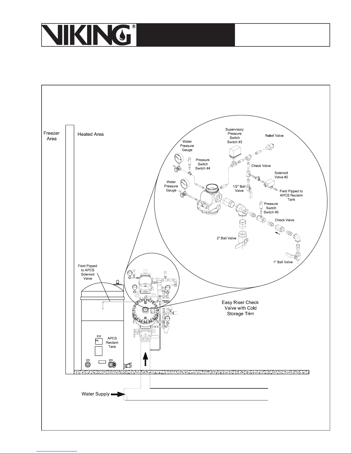
5. Easy Riser® Check Valve with Cold Storage Trim
Figure 24 - Easy Riser® Check Valve with Cold Storage Trim
Page 34
Page 34
March 7, 2008
ESFR PRE-PRIMED SINGLE
TECHNICAL DATA
INTERLOCK PREACTION
COLD STORAGE SYSTEM
The Viking Corporation, 210 N Industrial Park Road, Hastings MI 49058
Telephone: 269-945-9501 Technical Services 877-384-5464 Fax: 269-945-4495 Email: [email protected]
A. Cold Storage Trim with Automatic Pressure Control System
In cold storage areas where temperatures can fluctuate, over-pressurization of the system can
occur. The Automatic Pressure Control System (APCS) is used to prevent this from occurring.
The pressure relief valve (PRV) operates when the set point of 205 PSI (14.1 Bar) is reached.
Normal operation of the PRV includes operation at 90-105% of the set point and closing at 80%
of the set point. The Automatic Pressure Control System (APCS) is designed to maintain a safe
operating pressure below the set point of the PRV and above the maximum residual or static
pressure of water supply system or maximum set pressure of the system pressure switch.
The Automatic Pressure Control Trim is included with the Easy Riser® Cold Storage Trim and
installed on the primary Easy Riser® Check Valve.
The APCS includes an electronic digital pressure switch that includes a normally open SPST
switch that is set to close at a pressure below the PRV set point and open above the static
water supply or shut-off pressure of the riser system. A waterflow switch is to be installed on
the non-interruptible alarm port of the conventional trim on the deluge valve. A normally closed
solenoid valve is to be installed on the cold storage trim at the ¼” connection provided. A 115220 VAC, (50 or 60 Hz) GFI protected electrical power supply is to be provided directly to the
switch.
During normal operating condition, the propylene glycol within the system piping network is
pressurized to 50 PSI (3.45 Bar). The APCS uses a digital pressure switch (Switch #4) in
conjunction with a 120 VAC solenoid (Switch #2) to relieve pressure from the system when
the pressure exceeds 85 PSI (5.86 Bar). The digital pressure switch (#4) comes factory set to
operate and energize the solenoid (#2) at 85 PSI (5.86 Bar). The digital pressure switch will
change state and remove power from the solenoid (#2) at 75 PSI (5.17 Bar).
The digital pressure switch (#4) and solenoid (#2) are wired and powered from a dedicated
115-220 VAC (50 or 60 Hz) GFI protected power supply and routed through a water flow pressure switch (#2) as shown in Figure 39. These devices operate independently and are not
connected to either the release control panel or the CS-1 tank and pump unit. The normally
closed water flow pressure switch prevents the APCS from operating under normal water flow
conditions.
The pressure switch on the deluge valve will make the APCS inoperable when the detection
system causes the deluge valve to open. This prevents water flow from the APCS.
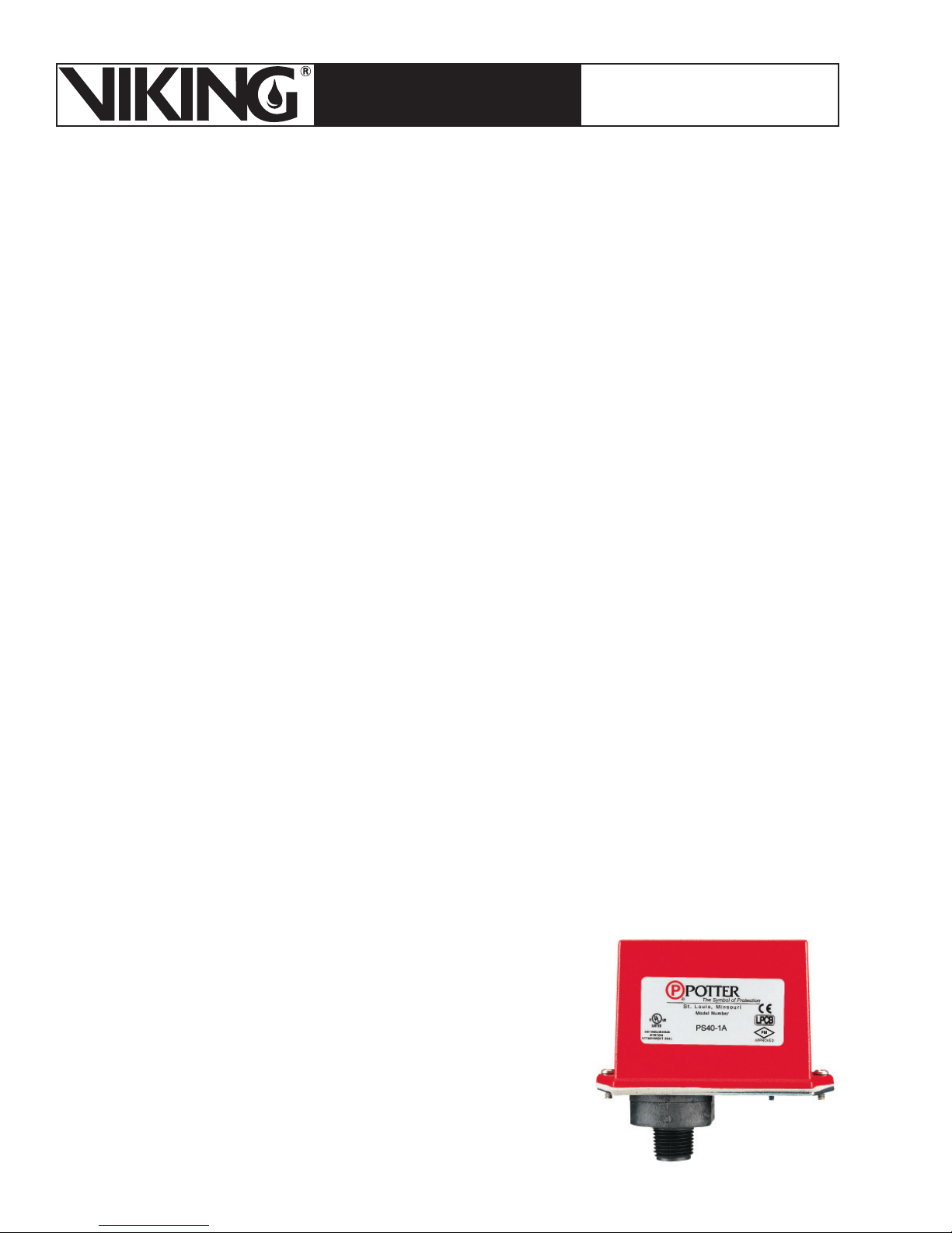
1. Supervisory Pressure Switch (PS-40)
The Automatic Pressure Control System includes a
PS-40 Supervisory Pressure Switch that is installed
on the primary Easy Riser
the appropriate supervisory circuit on the Viking VFR400 to annunciate a supervisory signal upon a low
pressure condition with the propylene glycol. It is
recommended to set the switch to activate at 30 PSI
(2.07 Bar).
®
Check Valve and wired to
Page 35
March 7, 2008
ESFR PRE-PRIMED SINGLE
TECHNICAL DATA
The Viking Corporation, 210 N Industrial Park Road, Hastings MI 49058
Telephone: 269-945-9501 Technical Services 877-384-5464 Fax: 269-945-4495 Email: [email protected]
INTERLOCK PREACTION
COLD STORAGE SYSTEM
Page 35
6. Digital Pressure Switch
A. Description
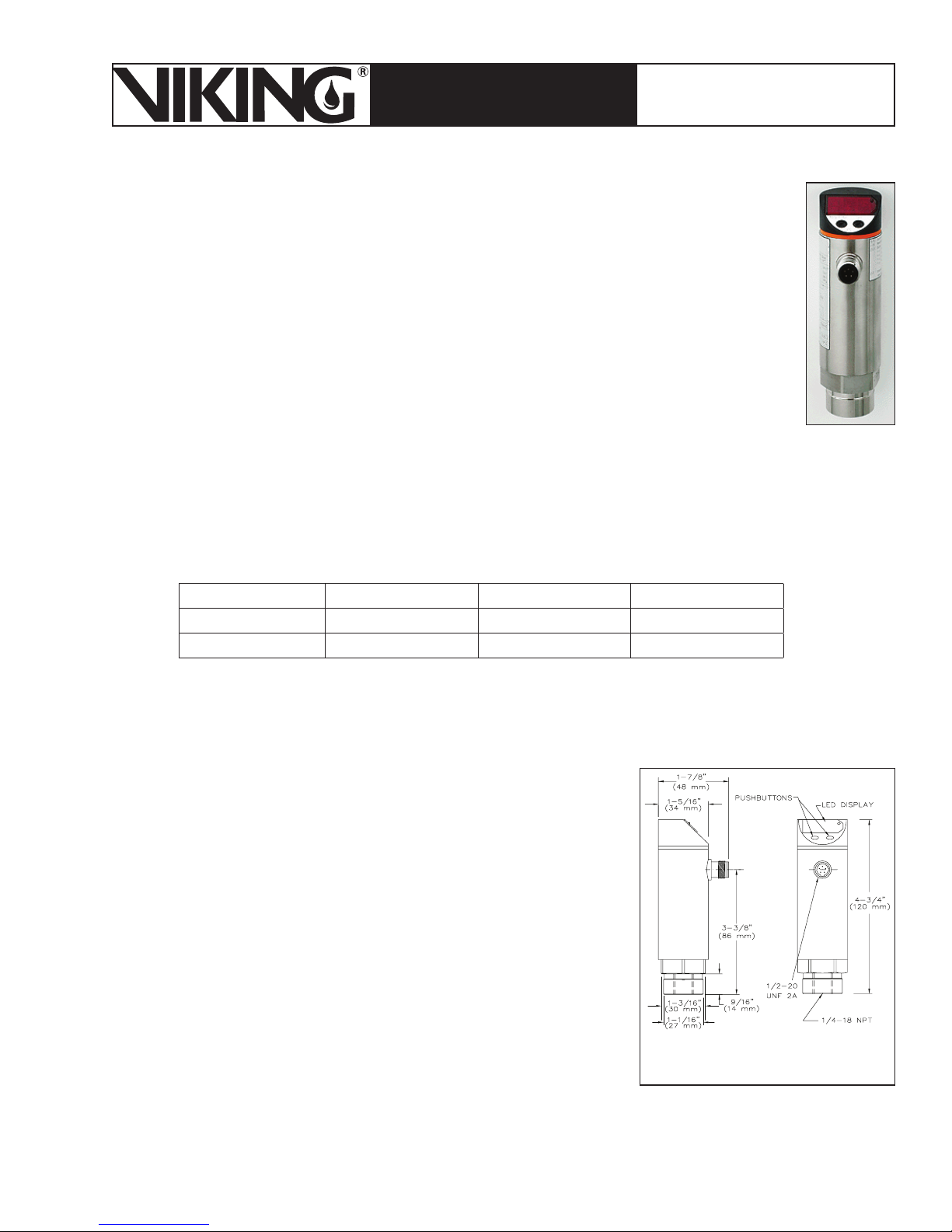
Viking Supervisory Pressure Switches (#4, 5, & 6) are factory programmed
electronic digital pressure switches installed in three locations of the ESFR Cold
Storage System. The pressure switches are designed to initiate an electric signal
at a predetermined low pressure setting or a predetermined high pressure setting
to maintain system antifreeze solution pressure, relieve high pressure or start the
CS-1 Pump. Viking Supervisory Pressure Switches are SPDT pressure transducer switches. The Switches show the current pressure on the LED display
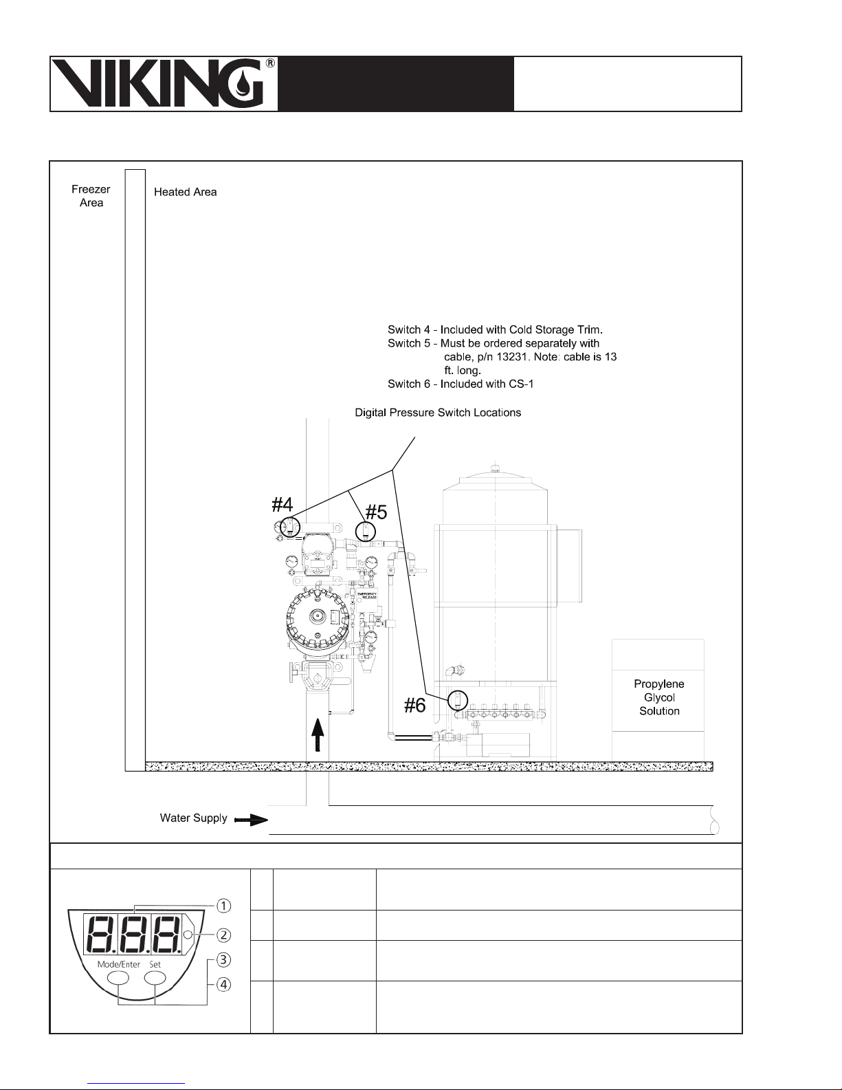
The pressure switches are used in each of the following locations (refer to Figure
25):
On the Automatic Pressure Control System (Switch #4) (Included with Cold Storage Trim)
•
On the system riser to control the solenoid valve (Switch #5) (Must be ordered separately)
•
On the CS-1 pump unit to control the pump (Switch #6) (Included with CS-1 Tank and
•
Pump)
B. Technical Data
Factory Settings: Switch # 4 (N/O) Switch # 5 (N/C) Switch # 6 (N/C)
Cut-Out: 75 PSI (5.17 Bar) 50 PSI (3.45 Bar) 75 PSI (5.17 Bar)
Cut-In: 85 PSI (5.86 Bar) 40 PSI (2.76 Bar) 45 PSI (3.1 Bar)
Specifications:
Dimensions: 1-7/8” (48 mm) W x 4-3/4” (120 mm) H (See Figure 25)
Pressure Connection: ¼” female NPT
Electrical Connection: ½” UNF-Connector, angled design
Maximum System Pressure: 175 PSI (12 Bar)
Voltage: 85-265 AC (45-65 HZ)
Current Rating [mA]:
2.5A @ 68 °F (20 °C)
1.5A @ 113 °F (45 °C)
1A @ 140 °F (60 °C)
0.25A @ 158 °F (70 °C)
Current Consumption: < 10 mA
Protection: IP65, Protection Class: II
Operating Temperature: -13 °F (-25 °C) to 176 °F (80 °C)
Not for use in hazardous locations
Cable Part Number 13231 is 13 ft (4 m) long
Material Standards:
Stainless Steel (303S22), ceramics; FPM (Viton)
Housing: EPDM/X (Santoprene), FPM (Viton), PA, Pocan, PC (Macrolon), Stainless Steel
(304S15)
Body: TPU (urethane)
Figure 25 - Switch
Dimensions
Page 36
Page 36
March 7, 2008
ESFR PRE-PRIMED SINGLE
TECHNICAL DATA
INTERLOCK PREACTION
COLD STORAGE SYSTEM
The Viking Corporation, 210 N Industrial Park Road, Hastings MI 49058
Telephone: 269-945-9501 Technical Services 877-384-5464 Fax: 269-945-4495 Email: [email protected]
Figure 26 - Digital Pressure Switch Locations
Figure 27: Controls and Visual Indication
1 LED display
2 LED red Switching status; lights if the output has switched
3 Mode/Enter button
4 Set button
Display of the system pressure, display of parameters
and parameter values.
Selection of the parameters and acknowledgment
of the parameter values.
Setting of the parameter values (scrolling by holding pressed;
incremental by pressing briefly)
Page 37

March 7, 2008
Page 37
ESFR PRE-PRIMED SINGLE
TECHNICAL DATA
INTERLOCK PREACTION
COLD STORAGE SYSTEM
The Viking Corporation, 210 N Industrial Park Road, Hastings MI 49058
Telephone: 269-945-9501 Technical Services 877-384-5464 Fax: 269-945-4495 Email: [email protected]
Nut: Brass, nickel plated
Wrench Flats: 30 mm
Ordering Information:
Part Numbers: Switch - 13057 (Must be ordered for Switch #5)
Cable - 13231
C. Operating Modes
Run Mode (normal operating mode):
When the supply voltage has been applied, the unit is in the Run mode. It monitors and switches the output according to the set parameters. The display shows the current system pressure.
The red LED indicates the switching state of the output.
Display Mode (indication of parameters and the set parameter values):
When the “Mode/Enter” button is pressed for a short time, the unit passes to the Display
mode. Internally it remains in the operating mode. The parameter names are scrolled with
each pressing of the “Mode/Enter” button. When the “Set” button is pressed for a short time,
the corresponding parameter value is displayed for approximately 15 seconds. Then the unit
returns to the Run mode.
Locking / Unlocking
The units are electronically locked to prevent unwanted adjustment of the set parameters;
Press (in Run mode) both setting buttons for 10 seconds. As soon as the indication goes out,
the unit is locked or unlocked. Units are delivered from the factory in the locked state. With the
unit in the locked state, “Loc” is indicated briefly when you try to change parameter values.
D. Installation
Before installing or removing a pressure switch, make sure that no pressure is applied
to the system.
1. When installing the switch, apply Teflon tape sealant to the male threads only.
2. Install the Supervisory Pressure Switch in the ¼” NPT connection. Use a wrench applied
to the wrench flats to tighten the unit. Do not over-tighten. Mount the switch in the upright
position (threaded connection down).
3. To wire the unit proceed as follows:
a. De-energize electrical circuits involved.
b. Connect cable (Viking Part No. 13213) to the ½” conduit opening provided.
c. Connect electrical circuitry for the signalling device and auxiliary equipment being con-
trolled by the switch. Refer to the wiring diagrams. Wire all devices to national and local
codes and requirements of the Authority Having Jurisdiction.
4. Energize the circuits.
1. Electrical Connection:
The unit must only be connected by a certified electrician. National and international regulations for the installation of electrical equipment must be observed. Caution: For the output
circuit, the same protective measures as for the supply circuit must be taken. A 115 VAC
(60 HZ) or 220 VAC (50 HZ) electrical power supply is to be provided directly to the switch
when used for APCS. Alternately, connect to the CS-1 panel. When used for system control, direct connection to the switch must be made with Viking Cable Part No. 13231.
Page 38

Page 38
March 7, 2008
ESFR PRE-PRIMED SINGLE
TECHNICAL DATA
INTERLOCK PREACTION
COLD STORAGE SYSTEM
The Viking Corporation, 210 N Industrial Park Road, Hastings MI 49058
Telephone: 269-945-9501 Technical Services 877-384-5464 Fax: 269-945-4495 Email: [email protected]
E. Inspections, Tests and Maintenance
Operate and test the Supervisory Pressure Switch after installation, prior to start-up, and periodically as required in the Viking technical data pages, the installation standards, and/or the Authority
Having Jurisdiction. Quarterly testing of Pressure Supervisory Switches is recommended. Refer
to ESFR Cold Storage System data page 45a-j for testing requirements and procedures.
NOTICE: The owner is responsible for maintaining the fire-protection system and devices in
proper operating condition. For minimum maintenance and inspection requirements, refer to
NFPA 25 and Viking’s ESFR Cold Storage System Manual.
1. Periodic Test and Maintenance
Caution: For auxiliary equipment controlled by operation of the switch, take the steps nec-
essary to prevent unwanted operation or shutdown of those devices when testing.
Warning: Any system maintenance that involves placing a control valve or detection
system out of service may eliminate the fire-protection capabilities of that system. Prior
to proceeding, notify all Authorities Having Jurisdiction. Consideration should be given to
employment of a fire patrol in the affected areas.
1. Refer to Viking technical data page 45a-j and the ESFR Cold Storage System Manual
for testing and maintenance instructions.
2. If test is satisfactory, reset all necessary equipment, and place the system in service.
2. Supervisory Switch Adjustment
Consult the ESFR Cold Storage System technical data pages for recommended pressure
settings for each location where the Supervisory Pressure Switch is installed on the system. The switches are factory set. If adjustment is necessary, proceed according to the
instructions given below.
1. If the unit is in the locked state, “Loc” is indicated briefly when you try to change parameter values, press (in Run mode) both setting buttons for 10 seconds. As soon as the
indication goes out, the unit is unlocked.
2. Verify pressure settings of the switch.
3. Test for proper operation of the device.
4. The unit can be electronically locked to prevent unwanted adjustment of the set parameters; Press (in Run mode) both setting buttons for 10 seconds. As soon as the indication goes out, the unit is locked. With the unit in the locked state, “Loc” is indicated briefly
when you try to change parameter values.
5. Reset all necessary equipment and place the system in service. Refer to the ESFR Cold
Storage System technical data pages.
Page 39
March 7, 2008
Page 39
ESFR PRE-PRIMED SINGLE
TECHNICAL DATA
INTERLOCK PREACTION
COLD STORAGE SYSTEM
The Viking Corporation, 210 N Industrial Park Road, Hastings MI 49058
Telephone: 269-945-9501 Technical Services 877-384-5464 Fax: 269-945-4495 Email: [email protected]
7. Propylene Glycol Solution Reclaim Tank
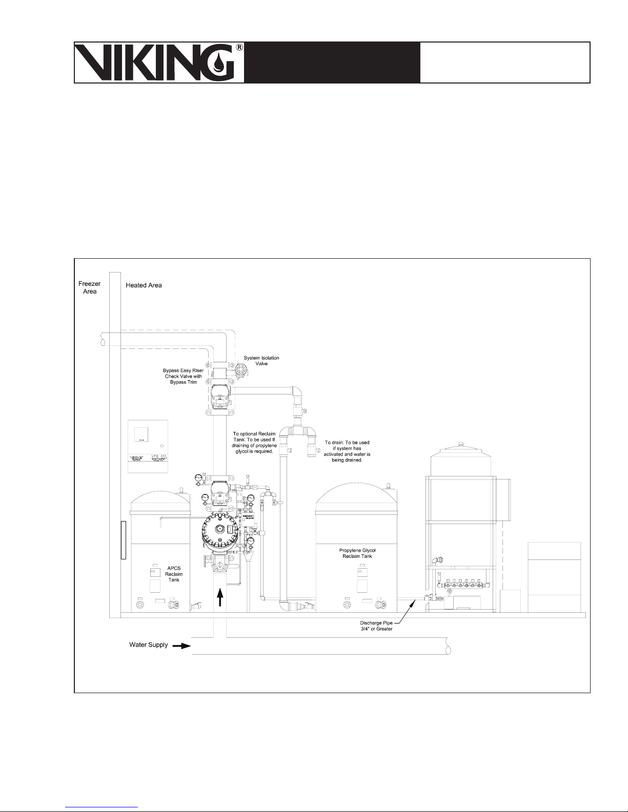
Viking recommends a reclaim tank with at least the capacity of the largest system be available for
system draining. The system drain piping should be arranged to discharge to the reclaim tank. In
addition, (1) smaller reclaim tank for all systems should be installed and connected to the pressure relief valve on the automatic pressure control system.
Figure 28 - Propylene Glycol Reclaim Tank
Page 40
Page 40
March 7, 2008
ESFR PRE-PRIMED SINGLE
TECHNICAL DATA
INTERLOCK PREACTION
COLD STORAGE SYSTEM
The Viking Corporation, 210 N Industrial Park Road, Hastings MI 49058
Telephone: 269-945-9501 Technical Services 877-384-5464 Fax: 269-945-4495 Email: [email protected]
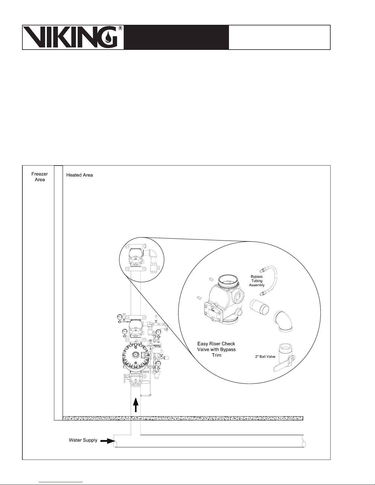
8. Bypass Easy Riser® Check Valve with Bypass Trim
A second Easy Riser® Check Valve is required to be installed above the Primary Easy Riser
Check Valve. The Isolation Check Valve is identical to the Primary Easy Riser Check Valve, but
requires bypass trim.
®
The bypass Easy Riser
area to a warm area or a warm area to a cold area in the case of installations in both coolers
and freezers. Frost is likely to occur on the piping downstream of the bypass Easy Riser Check
Valve. This piping and bypass check valve must be insulated with standard freezer insulation. In
situations where the valve is installed in the horizontal position, it must be installed with the face
plate facing up.
Check Valve is installed to “dead head” thermal transfer from a cold
Figure 29 - Easy Riser Check Valve with Bypass Trim
Page 41
March 7, 2008
ESFR PRE-PRIMED SINGLE
TECHNICAL DATA
The Viking Corporation, 210 N Industrial Park Road, Hastings MI 49058
Telephone: 269-945-9501 Technical Services 877-384-5464 Fax: 269-945-4495 Email: [email protected]
INTERLOCK PREACTION
COLD STORAGE SYSTEM
Page 41
A. Installation
The wiring diagram shown in Figure 39 should be used for installation of the switches and
solenoid valve. In order to wire the pressure switches and solenoid valve to the power supply,
a NEMA 4 junction box and conduit components are required from the junction box to solenoid valve. A special cable included with the package is required for connection to the digital
switch.
The electric power supply required is 115-220 VAC, 50 or 60 Hz GFI protected. The supply
wire from digital switch to solenoi valve shall be wired through the non-interupted N.C. alarm
pressure swtich. See Figure 39 diagram.
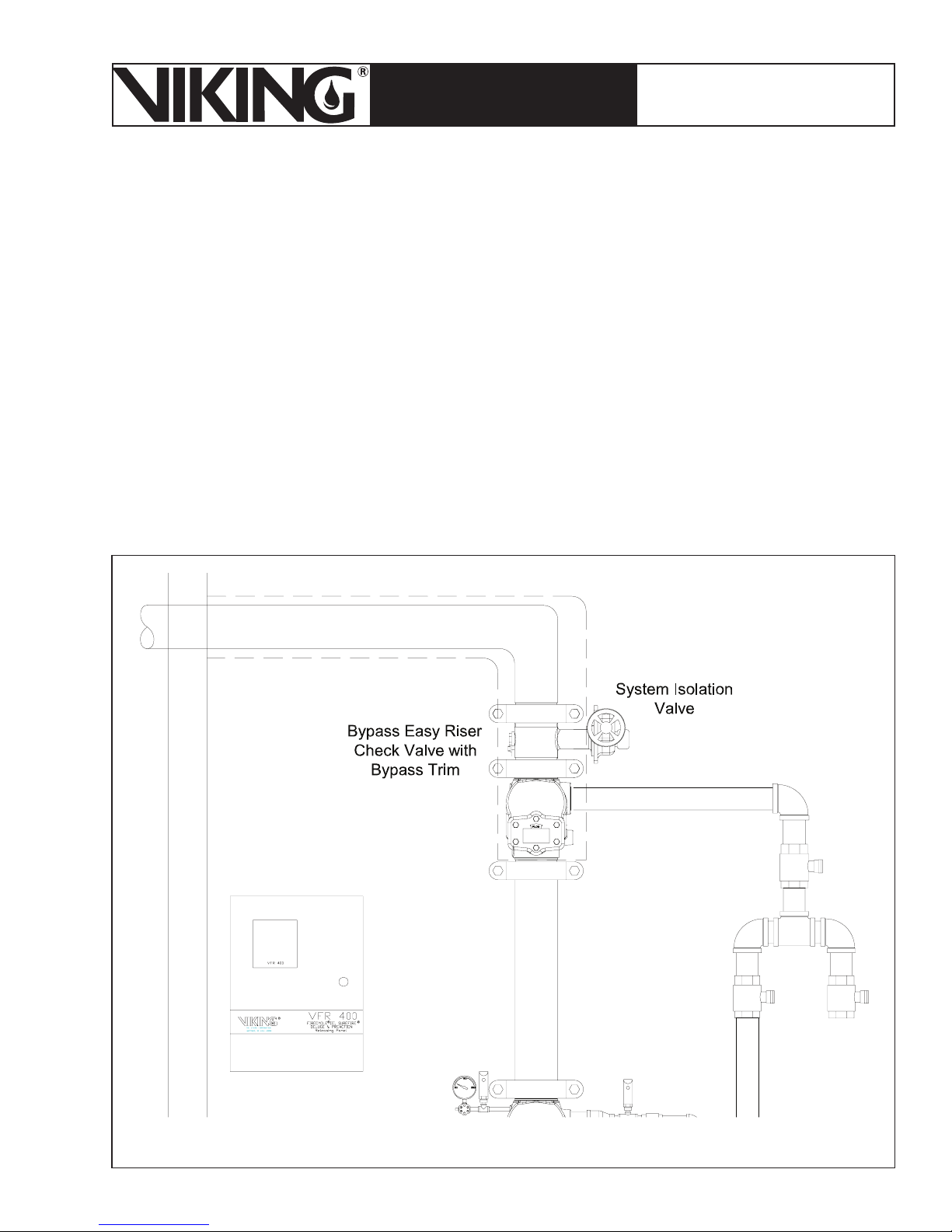
9. Downstream System Isolation Valve
The downstream System Isolation Valve allows the user to isolate the propylene glycol in the
system during system maintenance and testing procedures. If this valve is not installed, the
propylene glycol solution will be entirely drained from the system even in situations where such
drainage may not be desirable. The valve must be supervised in accordance with NFPA 13.
Figure 30 - Downstream System Isolation Valve
Page 42
Page 42
March 7, 2008
ESFR PRE-PRIMED SINGLE
TECHNICAL DATA
INTERLOCK PREACTION
COLD STORAGE SYSTEM
The Viking Corporation, 210 N Industrial Park Road, Hastings MI 49058
Telephone: 269-945-9501 Technical Services 877-384-5464 Fax: 269-945-4495 Email: [email protected]
10. CS-1 Tank & Pump Unit
A. Description
The Viking CS-1 Tank and Pump Package is an integrated storage tank and pumping system.
The tank and pump system automatically maintains the supervisory solution pressure in the
piping system above the supervisory alarm pressure until the detection system and sprinkler
is activated. The pump uses propylene glycol solution in the storage tank to maintain system
pressure and make up for minor system leaks.
The system is designed to accept up to 50% propylene glycol and water premix solution. It is
recommended that certified premix be used. Do not mix different antifreeze solutions within
the system.
WARNING: Motors, electrical equipment, and controls can cause electrical arcs that will
ignite a flammable gas or vapor. Never operate or repair in or near a flammable gas,
vapor, excessive dust or steam. Never store flammable liquids or gases near the unit.
Safety:
This equipment is designed to be safe in the use for which it was planned, provided it is
installed, started up, operated, and maintained in accordance with the instructions in this
manual. Therefore, all personnel who install, use, or maintain the equipment must understand this manual. The unit contains electrical components that operate at line voltage and
moving parts. Before working on the unit, isolate and lock it out from the electrical supply.
All maintenance operations must be performed by qualified persons who have knowledge
in the necessary precautions.
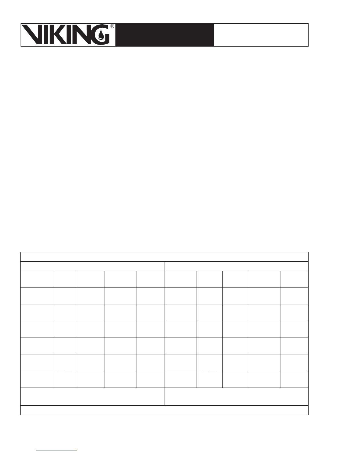
Table 7 - Ordering Information
US Power Supply Option (60 Hz) International Power Supply Option (50 Hz)
Part
Number*
Risers
13050-1 1
13050-2 2
13050-3 3
13050-4 4
13050-5 5
13050-6 6
US Power Supply Voltage suffixes:
A = 208 V, B = 230 V, C = 460 V, D = 575 V.
*Add voltage suffix after part number The pump furnished in all units is 3 HP, 3 Phase.
Tank
Size
65 gal
(246 L)
65 gal
(246 L)
160 gal
(606 L)
160 gal
(606 L)
160 gal
(606 L)
160 gal
(606 L)
Solenoid
Valves
Control
Relays
Part
Number*
1113051-1 1
2213051-2 2
3313051-3 3
4413051-4 4
5513051-5 5
6613051-6 6
International Power Supply Voltage suffixes:
E = 380V
Risers
Tank
Size
65 gal
(246 L)
65 gal
(246 L)
160 gal
(606 L)
160 gal
(606 L)
160 gal
(606 L)
160 gal
(606 L)
Solenoid
Valves
Control
Relays
11
22
33
44
55
66
Page 43
March 7, 2008
Page 43
ESFR PRE-PRIMED SINGLE
TECHNICAL DATA
INTERLOCK PREACTION
COLD STORAGE SYSTEM
The Viking Corporation, 210 N Industrial Park Road, Hastings MI 49058
Telephone: 269-945-9501 Technical Services 877-384-5464 Fax: 269-945-4495 Email: [email protected]
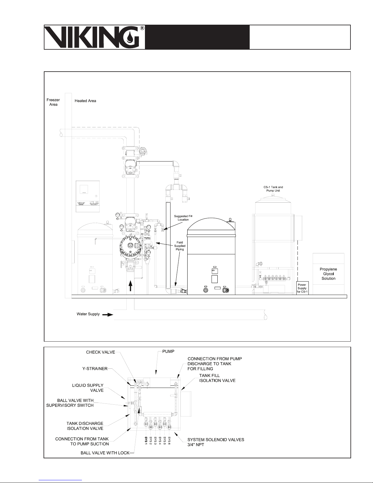
Figure 31 - CS-1 Tank and Pump Package
Figure 32 - Top View
with Upper Frame and
Tank Removed
Page 44

Page 44
ESFR PRE-PRIMED SINGLE
TECHNICAL DATA
The Viking Corporation, 210 N Industrial Park Road, Hastings MI 49058
Telephone: 269-945-9501 Technical Services 877-384-5464 Fax: 269-945-4495 Email: [email protected]
INTERLOCK PREACTION
COLD STORAGE SYSTEM
March 7, 2008
B. Technical Data
NOTE: The pressure switch (#6) on the CS-1 pump unit is factory set at cut-in pressure
and cut-out pressure. The pressure downstream of the Easy Riser® Check Valve is maintained at 50 PSI Max to 35 PSI Min. (3.4 bar - 2.4 bar) by digital pressure switch (#5).
C. Installation
1. Handling
Move the CS-1 on the shipping pallet as close to the final location as possible. Always lift
the unit from underneath. Never lift the unit when it is full of liquid. Personal injury and/or
equipment damage could result.
Ensure that all equipment used to lift the CS-1 is capable of lifting the weight. Nylon straps
and soft rigging devices should be used whenever possible to protect the components and
finish.
If the unit is being transported overhead, be sure that all personnel are alerted and safety
procedures are followed.
2. Location
Install the CS-1 indoors in a clean, dry , non-corrosive environment. This equipment is not to
be installed outdoors exposed to the weather. Position the CS-1 in an upright position on a
solid, level, vibration-free surface capable of supporting the weight of the unit and liquid in
the tank. Bolt the unit to the floor using the bolt holes provided in the frame. Always shim
the unit level before bolting it to the floor. Install the CS-1 in a protected, well-ventilated area
where the ambient temperatures are between 40 °F and 100 °F (4.4 °C to 37.8 °C).
Locate the CS-1 to allow access to supply and discharge connections. Clearance around
the unit should be at least 24” (610 mm) on all sides for maintenance. Some jurisdictions
require specific clearances around equipment. Check with all local Authorities to ensure
compliance with applicable state, local, and national codes.
3. Piping and Connections
A slight downward slope from the supply container to the CS-1 supply valve connection is
recommended to maintain positive head on the pump inlet.
Always use a backup wrench when making piping connections to avoid damage to the
unit’s piping.
Size piping between the CS-1 and the system 3/4” or greater to minimize pressure
drop. Clean black pipe is acceptable. Too small of a line size restricts pump flow and
causes excessive back pressure, lowering capacity when filling the system. Lower capacity while filling the system requires longer fill times. If the pump stops before obtaining set
system pressure, the CS-1 setting will require being increased. The sprinkler system must
contain air vent/bleed valves at all local high points. These are used to let air out of the
system while filling with antifreeze. Consult the system instructions for specifics.
Individual check valves and isolation valves are required for each system. This allows system maintenance without disturbing other systems the CS-1 is connected to.
Piping and/or hoses from the antifreeze supply containers to the unit should be sloped
downhill slightly to provide positive head on the pump suction connection. These lines
should be as large as possible and as short as possible to provide unrestricted flow to the
Page 45

March 7, 2008
Page 45
ESFR PRE-PRIMED SINGLE
TECHNICAL DATA
INTERLOCK PREACTION
COLD STORAGE SYSTEM
The Viking Corporation, 210 N Industrial Park Road, Hastings MI 49058
Telephone: 269-945-9501 Technical Services 877-384-5464 Fax: 269-945-4495 Email: [email protected]
pump while filling. A separate shut-off valve in the supply line is required.
Unit piping is copper, brass and bronze. An aluminum manifold is included for mounting
multiple system solenoids. Use dielectric unions to isolate copper piping from iron piping, if
used, to reduce the possibility of electrolytic action on pipes and other components.
All pipes should be de-burred and threaded to a proper depth and length before installation.
Threads should be inspected for cleanliness and depth of cut. Good quality pipe compound
should be used to ensure a good, leak-tight fit of piping components.
NOTE: Pipe must be supported separately from the CS-1. At no time should the CS-1
support the weight or load of the pipe. Acceptable pipe mounting devices would be
unistrut supports anchored to walls, hangers suspended from ceilings, or pedestals
mounted from the floor. Be sure all pipe installation conforms to all building and fire
codes.
4. Electrical Connections
SERIOUS PERSONAL INJURY AND DAMAGE TO THE CS-1 WILL OCCUR IF IT IS
CONNECTED TO A POWER SOURCE OTHER THAN THE VOLTAGE LISTED ON THE
DA T A TAG. THE MANUFACTURER IS NOT LIABLE FOR DAMAGE DUE TO IMPROPER
WIRING, PROTECTION, OR ELECTRICAL SERVICE INSTALLATION.
When installing electrical service to this machine, comply with the National Electric Code
as well as state and local building codes.
Failure to install the proper electrical protection can result in personal injury , fire, equipment
damage or death. The manufacturer is not responsible for damage or injury caused by lack
of or improperly installed electrical protection.
Electrical connection to the unit is made in the control enclosure. Connect appropriate
supply power to the terminals provided. The supply wire must be of adequate size and no
other equipment should be connected to the same circuit. An arrow on the pump indicates
the correct direction of rotation. If the pump rotates in the opposite direction, reverse the
rotation of the motor. Interchanging any two incoming 3-phase supply wires reverses rotation of 3-phase motors.
WARNING: Operating the pump in the wrong direction may damage the pump. Verify
pump rotation is correct before placing the unit in service. Make sure there is liquid
on the suction side of the pump before checking rotation.
Connect system inputs to the proper terminals in the CS-1 control enclosure. Each system
pressure switch and alarm flow switch are connected as shown on the electrical schematic.
NOTE: All system inputs must be connected before operating the unit. System
valves will not respond unless the system pressure switch and flow alarm switch
are connected correctly.
5. Start-Up
The following points must be verified before putting the unit into service. Correct any discrepancies before operating the unit:
The unit is bolted to a firm level surface.
•
Area temperature will always remain between 40 °F and 100 °F (4.4 °C to 37.8 °C).
•
Page 46
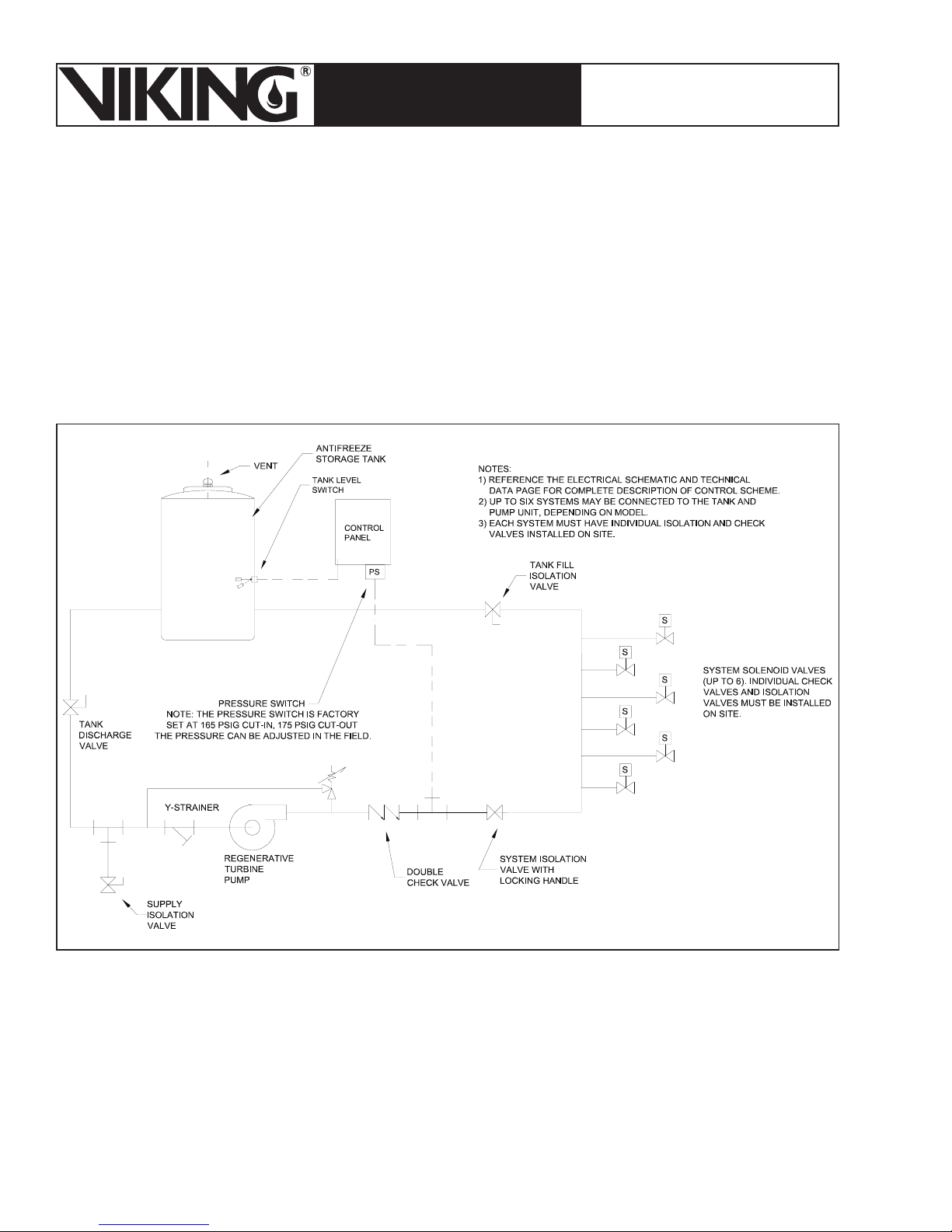
Page 46
March 7, 2008
ESFR PRE-PRIMED SINGLE
TECHNICAL DATA
INTERLOCK PREACTION
COLD STORAGE SYSTEM
The Viking Corporation, 210 N Industrial Park Road, Hastings MI 49058
Telephone: 269-945-9501 Technical Services 877-384-5464 Fax: 269-945-4495 Email: [email protected]
•
Dielectric unions, if needed, are installed between the pump station piping and system
piping.
•
All piping to and from the pump station is independently supported and does not place
any strain on the unit’s piping.
•
Power supplied to the unit is appropriate.
•
Pump rotation has been checked and is correct.
•
System inputs are connected according to the electrical schematic. All pressure
switches are set or programmed correctly.
•
Air can be vented from the system when filling with antifreeze.
Figure 33 - Flow Diagram
Page 47
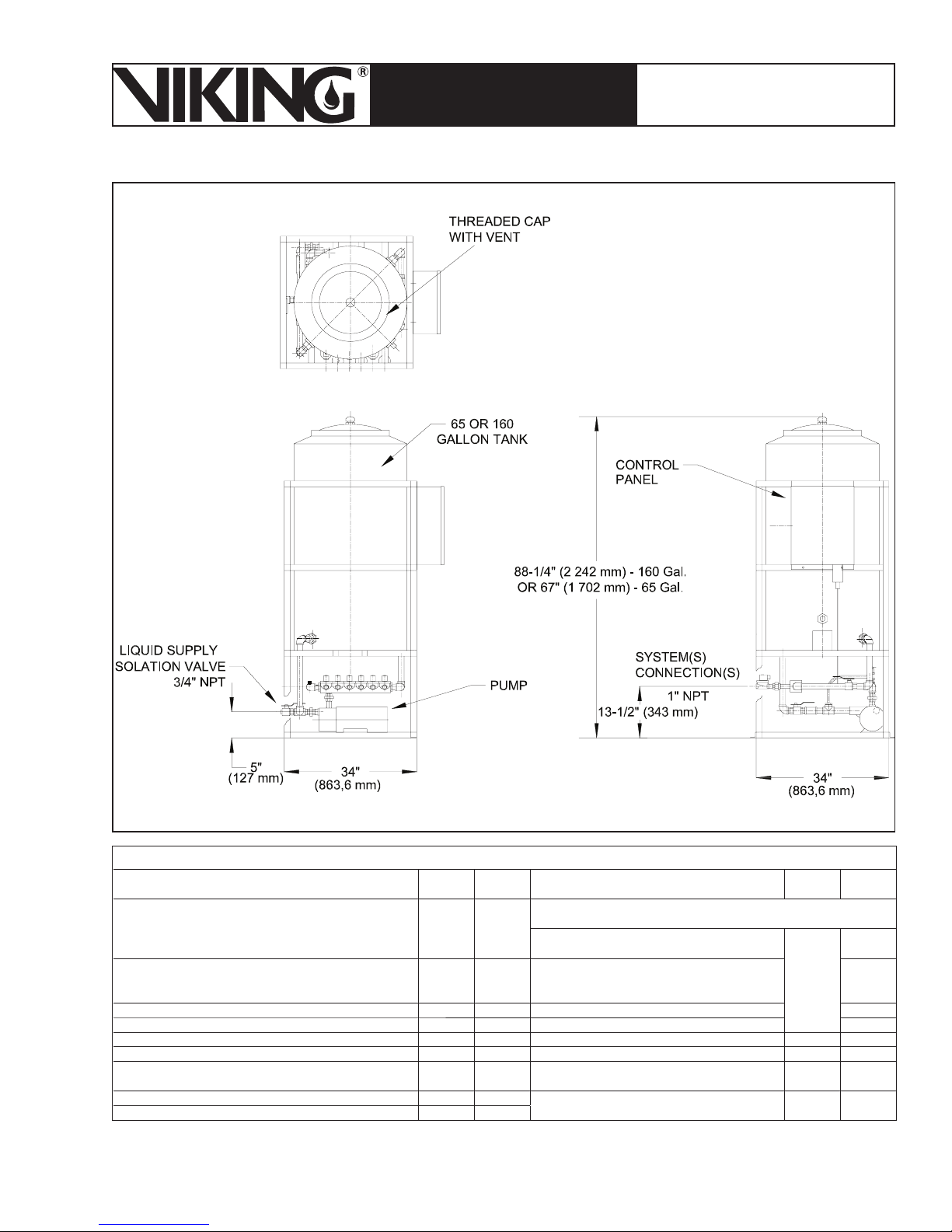
March 7, 2008
Page 47
ESFR PRE-PRIMED SINGLE
TECHNICAL DATA
INTERLOCK PREACTION
COLD STORAGE SYSTEM
The Viking Corporation, 210 N Industrial Park Road, Hastings MI 49058
Telephone: 269-945-9501 Technical Services 877-384-5464 Fax: 269-945-4495 Email: [email protected]
Figure 34 - CS-1 Tank and Pump
Description
Pump Basic Repair Kit - Includes Seal Stationary
Element, Seal Stationary Seat, Casing O-Ring,
Impeller (Type “L”)
Level Switch, Stainless Steel Wetted Components,
½” NPT External Side Mounting, ½” NPT Conduit
Connection
Solenoid Valve, ¾” Normally Closed 120V-60 HZ 1 12955 460V-60 HZ-3 PH 13061
Solenoid Valve, ¾” Normally Closed 110V-50 HZ 1 13194 575V-60 HZ-3 PH 13062
Ball Valve, 1” 1 13055 Control Relay 1 13063
Double Spring Check Valve, Brass 1 13056 Transformer Primary Fuse, ½ AMP 2 13064
Pressure Switch, Factory Set at 165 cut-in, 175 psig
cut-out. Should be fi eld adjusted.
Pressure Switch Cable 1 13231
Magnetic Starter 1 13058
Table 8 - Recommended Spare Parts List
Rec.
Qty.
1 13052
1 13054 230V-60 HZ-3 PH 13060
1 13057 Transformer Secondary Fuse, 1 AMP 1 13065
P/N Description
Overload Heater (Indicate Unit Voltage for Correct Selection)
208V-60 HZ-3 PH
Pilot Light, Green LED, 120V, NEMA 4X 1 13066
Rec.
Qty.
3
P/N
13059
Page 48
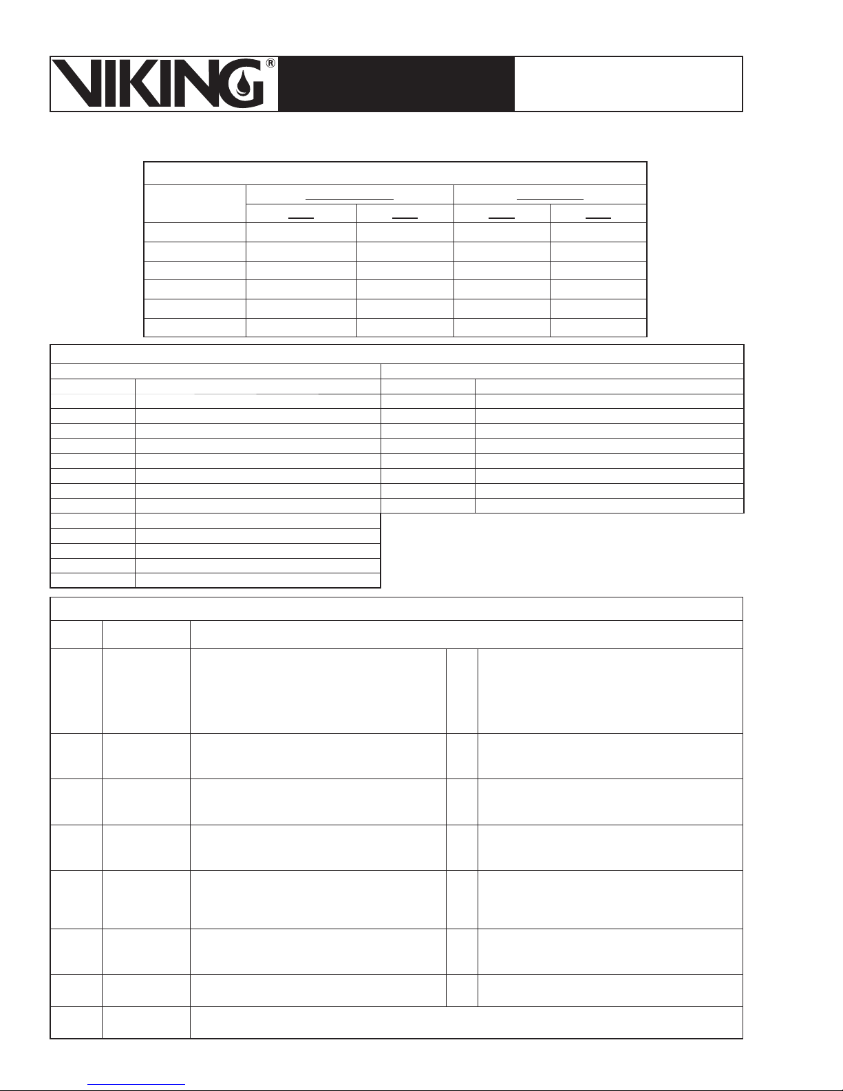
Page 48
March 7, 2008
ESFR PRE-PRIMED SINGLE
TECHNICAL DATA
INTERLOCK PREACTION
COLD STORAGE SYSTEM
The Viking Corporation, 210 N Industrial Park Road, Hastings MI 49058
Telephone: 269-945-9501 Technical Services 877-384-5464 Fax: 269-945-4495 Email: [email protected]
Table 9 - CS-1 Schematic Drawing Numbers
Drawing Number Manual Page
60Hz 50Hz 60Hz 50Hz
Single Riser 13050-1 13051-1 60-61 72-73
Two Risers 13050-2 13051-2 62-63 74-75
Three Risers 13050-3 13051-3 64-65 76-77
Four Risers 13050-4 13051-4 66-67 78-79
Five Risers 13050-5 13051-5 68-69 80-81
Six Risers 13050-6 13051-6 70-71 82-83
Table 10 - Inputs and Outputs
Inputs Outputs
Input 1 “Manual” position of Hand-Off- Auto Switch Output 1 “Power On” light
Input 2 “Auto” position of Hand-Off- Auto Switch Output 2 Pump Motor Starter Coil and “Pump” light
Input 3 Pressure Switch of Pumping Unit Output 3 System 1 Solenoid Valve
Input 4 Tank Level Switch Output 4 System 2 Solenoid Valve
Input 5 System 1 Inputs Output 5 System 3 Solenoid Valve
Input 6 System 2 Inputs Output 6 System 4 Solenoid Valve
Input 7 System 3 Inputs Output 7 System 5 Solenoid Valve
Input 8 System 4 Inputs Output 8 System 6 Solenoid Valve
Input 9 System 5 Inputs Output 9 Level Switch Relay Coil
Input 10 System 6 Inputs
Input 11 Switch A – Down Position
Input 12 Switch A – Up Position
Input 13 Switch B – Down Position
Input 14 Switch B – Up Position
Output 1“Power On”
Output
Output 3System 1
Output 4System 2
Output 5System 3
Output 6System 4
Output 7System 5
Output 8System 6
Output 9Level Switch
2
light
Pump Motor
Starter Coil and
“Pump” light
Solenoid Valve
Solenoid Valve
Solenoid Valve
Solenoid Valve
Solenoid Valve
Solenoid Valve
Relay Coil
Table 11 - Control Logic
Output 1 on when: Input 1 or Input 2 are on.
Output 2 on when: (Manual Mode System and
Tank Filling) Input 1 on + Input 3 on.
Output 3 on when: (Manual Mode) Input 1 on and
Input 5 on and Input 12 on and Input 13 off and
Input 14 off.
Output 4 on when: (Manual Mode) Input 1 on and
Input 6 on and Input 11 on and Input 13 off and
Input 14 off.
Output 5 on when: (Manual Mode) Input 1 on and
Input 7 on and Input 11 off and Input 12 off and
Input 14 on.
Output 6 on when: (Manual Mode) Input 1 on and
Input 8 on and Input 11 off and Input 12 off and
Input 13 on.
Output 7 on when: (Manual Mode) Input 1 on and
Input 9 on and Input 12 on and Input 14 on. -or-
Output 8 on when: (Manual Mode) Input 1 on and
Input 10 on and Input 11 on and Input 13 on.
Output 9 on when: Input 4 on.
-or-
-or- (Automatic Mode) Input 2 on and Input 5 on.
-or-
-or-
-or- (Automatic Mode) Input 2 on and Input 8 on.
-or- (Automatic Mode) Input 2 on and Input 10 on.
(Automatic Mode) Input 2 on + Input 3 on + Input
4 on +
And Internal Timer times to 10 minutes. The timer
begins when Manual or Automatic mode is started
and is reset when pump turns off in Automatic
Mode.
(Automatic Mode) Input 2 on and Input 6 on.
(Automatic Mode) Input 2 on and Input 7 on.
(Automatic Mode) Input 2 on and Input 9 on.
Page 49

March 7, 2008
ESFR PRE-PRIMED SINGLE
TECHNICAL DATA
The Viking Corporation, 210 N Industrial Park Road, Hastings MI 49058
Telephone: 269-945-9501 Technical Services 877-384-5464 Fax: 269-945-4495 Email: [email protected]
INTERLOCK PREACTION
COLD STORAGE SYSTEM
Page 49
D. CS-1 Control Scheme
1. Pump Operation
The pressure switch mounted on the CS-1 controls pump operation. When the pressure at
the CS-1 drops, the pump will turn on until the pressure at the CS-1 rises above a set level.
In “Automatic” mode, pump operation is inhibited if the level of liquid in the unit’s storage
tank drops below the level switch height.
In “Manual” mode, the pump operates when CS-1 pressure drops, a system valve is selected, if that system pressure is not met, and there is no alarm condition. The pump can
also fill the tank in Manual mode. For tank filling, the level switch position is not used and
the operator must start and stop the pump, using the “Man” position of the Man-Off-Auto
Switch on the control panel.
In Automatic mode, there is a 10-minute time delay between pump operations. After the 10minute delay, the pump operates if the CS-1 pressure drops and tank fluid level is above
the level switch height. When the pump shuts off, the 10-minute timer starts again and the
pump will not operate until 10 minutes is complete.
2. System Solenoid Valve Operation
Each system (riser) pressure switch and alarm pressure switch contacts are connected
in series to one input on the PLC. The system pressure switch opens on falling pressure.
The alarm pressure switch normally closed contacts are used and open in the alarm condition.
In Automatic mode, each system solenoid valve opens if its system pressure drops to
a low-pressure condition and there is no alarm pressure signal. In manual mode, each
system valve is selected by means of two selector switches and the solenoid valve opens
as long as system pressure is below the set-point value and there is no system alarm.*
Note: To operate in manual mode, all switches must be wired.
3. Level Switch Relay Coil Operation
The level switch relay coil is energized when the tank level is above the level switch height.
This is when tank level is satisfied. The switch relay coil de-energizes when tank level
drops to the level switch height, at low tank level.
E. Filling the Reservoir Tank
The CS-1 has been designed to fill the reservoir tank using either of two methods: gravity fill
or pumped fill. NOTE: This is NOT a self-priming pump. Manually prime or fill the reservoir for
prime.
*NOTE: Never leave the unit unattended when filling the system or tank. Running the
pump dry, without liquid, will damage pump seals and possibly damage pump impeller.
Follow the steps below:
1. Gravity Fill:
Turn off and isolate the electrical supply to the unit.
1.
Close Supply Isolation valve.
2.
Page 50

Page 50
March 7, 2008
ESFR PRE-PRIMED SINGLE
TECHNICAL DATA
INTERLOCK PREACTION
COLD STORAGE SYSTEM
The Viking Corporation, 210 N Industrial Park Road, Hastings MI 49058
Telephone: 269-945-9501 Technical Services 877-384-5464 Fax: 269-945-4495 Email: [email protected]
Connect the antifreeze supply container to the supply isolation valve. A flexible hose
3.
may be used, but must not restrict the flow from the supply container to the valve. An
additional isolation valve must be installed in the line between the supply container
and unit’s supply isolation valve.
Open the shut off valve on the supply container and supply isolation valve on the
4.
CS-1.
Open the pump suction isolation valve and allow liquid to enter the reservoir tank. If
5.
there is enough liquid in the supply container, the tank may be filled completely using
this method. The tank is full when the liquid level rises to the top of the straight section of the tank.
2. Pump Assist Fill:
If there is not sufficient liquid in the supply container to fill the tank or the tank fills too slowly ,
the pump on the CS-1 may be manually operated to speed up this process. Follow steps
1 to 4 above and 2 to 5 below to fill the storage tank using the pump. A slight downward
slope from the supply container to the valve connection is required to prime the pump and
maintain positive head on the pump inlet. Always use a backup wrench when making piping
connections to avoid damage to the unit’s piping.
1.
Close the tank discharge isolation valve and open the tank fill isolation valve.
2.
With the CS-1 “OFF-ON” switch in the “OFF” position, turn on power supply to the
unit.
3.
Position switches “A” and “B” in the center/off position. Switch the “Man-O-AUTO”
switch on the unit control panel to “Man” and the “OFF-ON” switch to “ON”. Liquid will
begin to fill the storage tank at the fill connection.
4.
Be careful to observe the liquid level to prevent overfilling. When the liquid level
reaches the top of the straight section of tank, switch the unit’s “Man-O-AUTO” switch
to “O”.
5.
Close the liquid supply isolation and tank fill isolation valves. Open the tank discharge
isolation valve.
F. Filling Systems
A suitable portable pump can be utilized to fill the system. (The CS-1 pump can be used for
filling the system initially at 15 GPM (56 l/min) to 100 ft head pressure or system static pressure. However, it is a less efficient pump for filling the system because of the duration of time
required to do so. To fill the system, the system solenoid on the CS-1 is connected to the liquid
supply isolation valve of the Easy Riser® Check Valve for that system. All pressure switches
must be installed and set. The system to be filled is selected using two toggle switches on the
CS-1 control enclosure. Antifreeze from the supply is pumped to the system piping. Pump operation is manually controlled during the fill process. The CS-1 pump is to be utilized to bring
the solution to maintenance pressure, and is designed to maintain system pressure once the
system is initially filled. Appropriate vent/bleed valves must be installed on each system’s piping at all local high points to allow air to escape while liquid fills the system.
NOTE: Never leave the unit unattended when filling the system. Running the pump dry,
without liquid, will damage pump seals and possibly damage the pump impeller.
Page 51
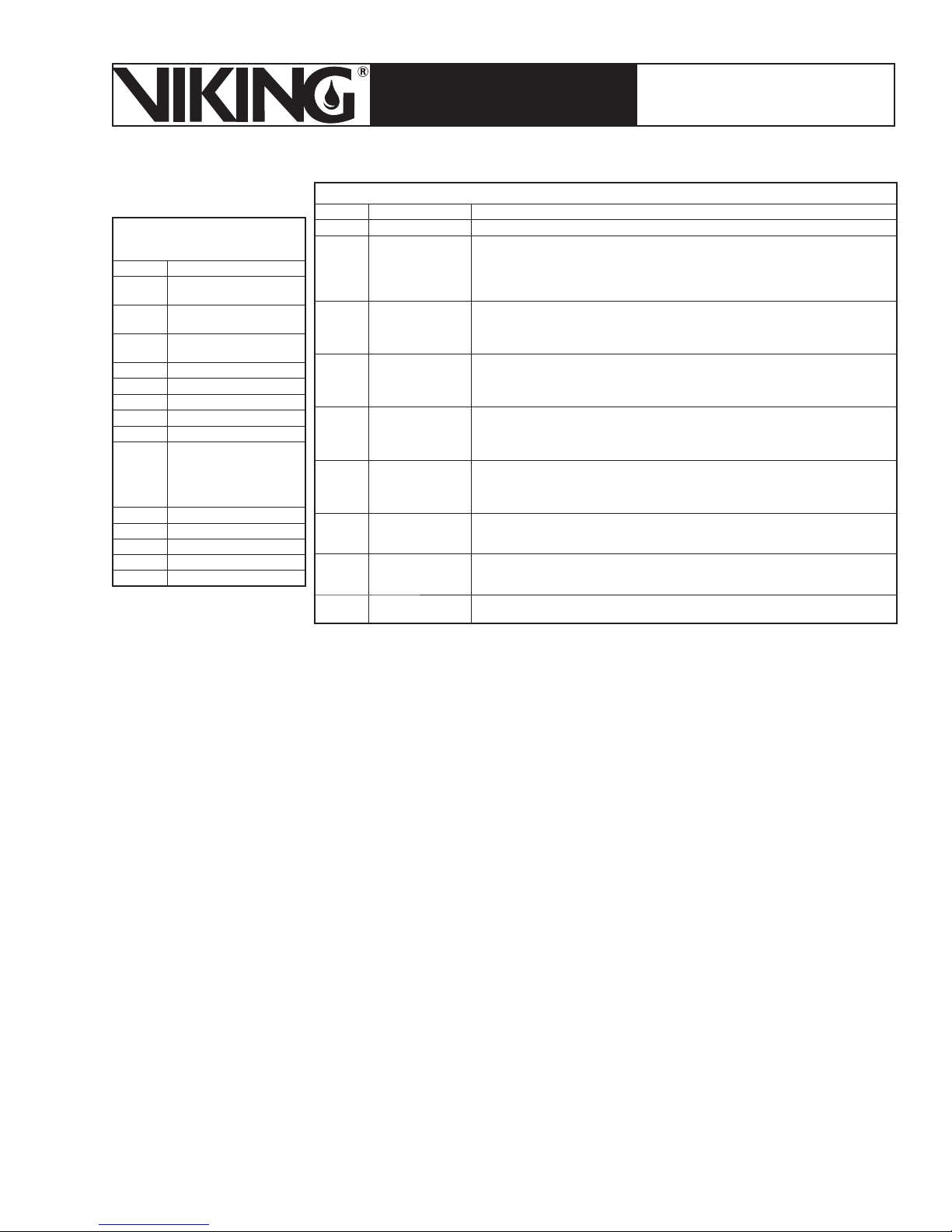
March 7, 2008
Page 51
ESFR PRE-PRIMED SINGLE
TECHNICAL DATA
INTERLOCK PREACTION
COLD STORAGE SYSTEM
The Viking Corporation, 210 N Industrial Park Road, Hastings MI 49058
Telephone: 269-945-9501 Technical Services 877-384-5464 Fax: 269-945-4495 Email: [email protected]
Table 13 - Output Descriptions
Output Description Control Logic
Table 12 - Input
Descriptions
Input Description
1 “Man” position of Hand-
Off- Auto Switch
2 “Auto” position of Hand-
Off- Auto Switch
3 Pressure Switch of
Pumping Unit
4 Tank Level Switch
5 System 1 Inputs
6 System 2 Inputs
7 System 3 Inputs
8 System 4 Inputs
9 System 5 Inputs
10 System 6 Inputs
11 Switch A – Down Position
12 Switch A – Up Position
13 Switch B – Down Position
14 Switch B – Up Position
1 “Power On” light Output 1 on when: Input 1 or Input 2 are on.
2 Pump Motor
Starter Coil and
“Pump” light
3 System 1
Solenoid Valve
4 System 2
Solenoid Valve
5 System 3
Solenoid Valve
6 System 4
Solenoid Valve
7 System 5
Solenoid Valve
8 System 6
Solenoid Valve
9 Level Switch
Relay Coil
Output 2 on when:
(Manual Mode System and Tank Filling) Input 1 on + Input 3 on. OR
(Automatic Mode) Input 2 on + Input 3 on + Input 4 on and Internal Timer times
to 10 minutes. The timer begins when Manual or Automatic mode is started and is
reset when pump turns off in Automatic Mode.
Output 3 on when:
(Manual Mode) Input 1 on and Input 5 on and Input 12 on and Input 13 off and Input
14 off. OR
(Automatic Mode) Input 2 on and Input 5 on.
Output 4 on when:
(Manual Mode) Input 1 on and Input 6 on and Input 11 on and Input 13 off and Input
14 off. OR
(Automatic Mode) Input 2 on and Input 6 on.
Output 5 on when:
(Manual Mode) Input 1 on and Input 7 on and Input 11 off and Input 12 off and Input
14 on. OR
(Automatic Mode) Input 2 on and Input 7 on.
Output 6 on when:
(Manual Mode) Input 1 on and Input 8 on and Input 11 off and Input 12 off and Input
13 on. OR
(Automatic Mode) Input 2 on and Input 8 on.
Output 7 on when:
(Manual Mode) Input 1 on and Input 9 on and Input 12 on and Input 14 on. OR
(Automatic Mode) Input 2 on and Input 9 on.
Output 8 on when:
(Manual Mode) Input 1 on and Input 10 on and Input 11 on and Input 13 on. OR
(Automatic Mode) Input 2 on and Input 10 on.
Output 9 on when: Input 4 on.
Follow the steps below:
Turn off and isolate the electrical supply to the unit.
1.
Close the liquid supply valve and Tank Fill isolation valves.
2.
If not already connected to fill the storage tank, connect the antifreeze supply container
3.
to the liquid supply valve. A flexible hose may be used, but must not restrict the flow from
the supply container to the valve. An additional isolation valve must be installed in the
line between the supply container and unit’s liquid supply valve. A slight downward slope
from the supply container to the unit’s valve connection is required to prime the pump and
maintain positive head on pump inlet. Always use a backup wrench when making piping
connections to avoid damage to the unit’s piping.
Open the shut-off valve on the supply container and liquid supply valve on the CS-1.
4.
Open high-point vent/bleed valves on the system.
5.
Select system to be filled using switches “A” and “B”. Use Table 14 or the table on the
6.
CS-1 Panel to determine switch “A” and “B” position.
With the CS-1’s “OFF-ON” switch in the “OFF” position, turn on the power supply to the
7.
unit.
Switch the “Man-O-AUTO” switch on the unit control panel to “Man”. Turn the “Off-On”
8.
switch to “ON”. Liquid will begin to fill the selected system.
As the system fills, monitor the system vent/bleed valves. Close each valve when liquid
9.
leaks from it.
When the liquid leaks from the uppermost vent/bleed valve, close the vent valve. The
10.
system pressure switch will close that system’s solenoid valve when set pressure is
established. The pump pressure switch will turn the pump off when set pressure is established.
Page 52

Page 52
March 7, 2008
ESFR PRE-PRIMED SINGLE
TECHNICAL DATA
INTERLOCK PREACTION
COLD STORAGE SYSTEM
The Viking Corporation, 210 N Industrial Park Road, Hastings MI 49058
Telephone: 269-945-9501 Technical Services 877-384-5464 Fax: 269-945-4495 Email: [email protected]
11.
If another system is to be filled, turn the “Man-O-AUTO” switch to “O” and select the next
system using switches A and B.
12.
Turn the “Man-O-AUTO” switch to “Man” and repeat steps 8 through 10.
13.
After filling all systems and the CS-1 tank, close the liquid supply valve.
All air must be out of the system before switching the unit to maintenance mode. Follow
14.
the system manufacturer’s recommendations to ensure all air is removed.
G. Operating in Maintenance Mode: Automatic
As previously stated, the CS-1 is designed to maintain the antifreeze pressure in the sprinkler system at a supervisory pressure of 50 PSI (3.4 Bar). A pressure switch installed in the
pump discharge line operates the pump between two pressures sensed in the unit’s piping. A
pressure switch on each system sends a signal to the CS-1 to open and close that system’s
solenoid valve.
Ensure all air is removed from system piping before placing the unit in automatic operation.
Liquid level in the storage tank must be above the level switch height or pump operation is
inhibited.
Close the liquid supply and tank fill isolation valves. Open the tank discharge isolation valve
and system liquid supply isolation valve.
With the “ON-OFF” switch “ON”, switch the “Man-O-AUTO” switch to the “AUTO” position. The
CS-1 is now operating in Maintenance mode.
NOTE: The CS-1 control system uses a time delay relay, set at 10 minutes, to limit pump
operation to six times per hour maximum. When the unit is first energized in “AUTO”, pump
operation is delayed for 10 minutes.
After 10 minutes, if the CS-1 piping is below the unit’s pressure switch setting, the pump motor
will operate, raising CS-1 manifold pressure.
The pump will turn off at the pressure switch cutout pressure.
Each system’s solenoid valve will open in response to system pressure switch.
System Selected Switch A Position Switch B Position
No System - Tank Fill Centered Centered
System 1 Up Centered
Table 14 -
Switch Settings
System 2 Down Centered
System 3 Centered Up
System 4 Centered Down
System 5 Up Up
System 6 Down Down
Page 53
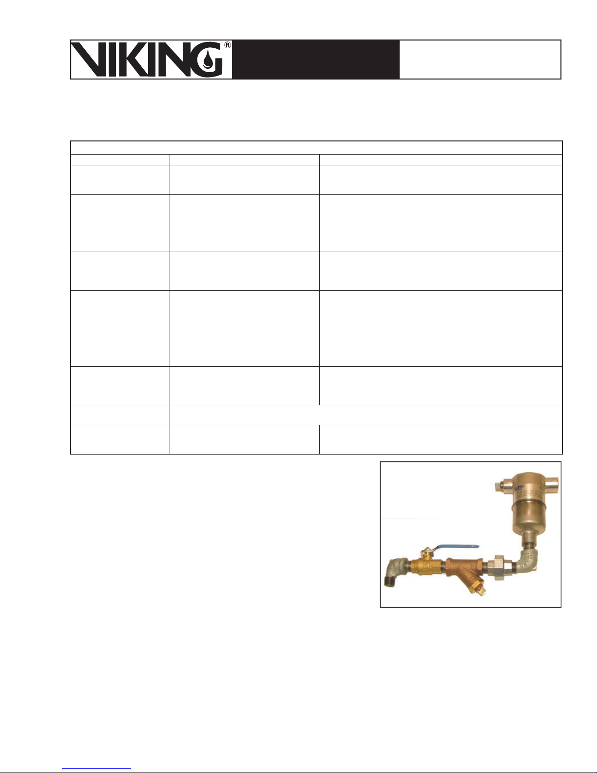
March 7, 2008
Page 53
ESFR PRE-PRIMED SINGLE
TECHNICAL DATA
INTERLOCK PREACTION
COLD STORAGE SYSTEM
The Viking Corporation, 210 N Industrial Park Road, Hastings MI 49058
Telephone: 269-945-9501 Technical Services 877-384-5464 Fax: 269-945-4495 Email: [email protected]
H. Inspections, Tests and Maintenance
Table 15 - Troubleshooting Guide
Problem Possible Causes Remedies
Unit will not turn on.
Pump does not operate
in Automatic mode when
CS-1 pressure drops.
Pump does not operate
in Automatic mode when
system valve opens.
Failure to pump.
Excessive power
consumption.
Other pump-related
problems.
Pump stops before
desired system pressure.
1) Power disconnected.
2) Blown fuse.
1) No power to unit.
2) Liquid level in tank low.
3) Magnetic starter overload tripped.
4) Time delay active.
5) Pump motor defective.
1) Pump operates on manifold
pressure, not system pressure. System
pressure switch setting is higher than
the CS-1 pressure switch setting.
1) Supply container empty.
2) Incorrect valve position.
3) Pump rotation backward.
4) Insuffi cient head pressure to pump
inlet.
5) Pump not up to speed.
6) Clogged suction line.
7) Air in suction line.
1) Pump not fully broken in.
2) Mechanical damage.
If other pump related problems are suspected, call the Viking Technical Services Department at 1-877-384-
5464.
Discharge pipe is too small or there is a
buildup of back pressure.
1) Check power at supply and unit, and correct.
2) Check fuses, replace as required, and determine cause of blown
fuse.
1) Verify power at unit terminal block.
2) Fill tank to proper height.
3) Verify and fi x cause of overload. Press reset button on starter.
4) Wait 10 minutes for time delay to time out. Correct leaks in
system.
5) Replace.
1) Verify system pressure switch setting is correct. The CS-1
pressure switch setting must not be adjusted higher. Adjust CS-1
switch setting lower if approved by factory.
1) Connect full supply container.
2) Correct valve position per instructions.
3) Correct pump rotation.
4) Raise supply container.
5) Check voltage.
6) Inspect and clean Y-Strainer.
7) Check for air in pump suction line.
1) Pump normally draws higher current during break-in period. This
condition will work itself out after several weeks.
2) Turn pump over by hand. If there are tight spots after break-in,
call Technical Services.
1) Increase pipe size.
2) Increase dS1 setting on pump switch.
3) Make sure dr1 setting is set to 0.50.
11. Air / Vacuum Vent
The Viking AV-1 device is a float operated automatic
air vent that is installed at high points of the sprinkler
system where air pockets can accumulate. As the system fills, air is automatically vented through the orifice
of the vent valve. When the system is full, the water or
antifreeze solution raises the float due to buoyancy and
shuts off the outlet orifice. As air throughout the system
accumulates at the high points of system piping, it will
be automatically expelled to provide air-free system
piping.
Airflow during venting is restricted due to differential pressure across vent orifice. It is recommended to slow fill the system initially to minimize the buildup of air in the system. See Table
16 for air flow capacity at various differential pressures.
Having the AV-1 installed on the end of each high-point branch line and/or main provides quicker and more complete drainage of system piping. This is because during drainage of system
piping, the AV-1 will open and allow air to enter and break the vacuum inside the piping.
Page 54

Page 54
March 7, 2008
ESFR PRE-PRIMED SINGLE
TECHNICAL DATA
INTERLOCK PREACTION
COLD STORAGE SYSTEM
The Viking Corporation, 210 N Industrial Park Road, Hastings MI 49058
Telephone: 269-945-9501 Technical Services 877-384-5464 Fax: 269-945-4495 Email: [email protected]
A. Installation
The AV-1 shall be installed at all high points of the ESFR Cold Storage piping, including branch
lines and main feed lines.
In order to install the AV-1 assembly in the space from the ceiling to the sprinkler, the isolation
ball valve and strainer must be installed in the horizontal position as illustrated in Figure 2 and
the AV-1 must be installed with the (2) outlet connections at the top location. This position is
critical in order to allow the float within the device to operate properly.
The outlet connection needs to be piped using 3/8” (9.5 mm) outside diameter plastic or copper
tubing unrestricted downward and away from protected product below. This is due to possible
small amounts of moisture that could spurt out during venting of the system. Copper is recommended in order to function during and after fire situations and long-lasting durability. Attach to
the ½” NPT vent connection as shown in Figure 32.
B. Ordering Information
Model AV-1 Valve and Trim Kit: Part Number 13495
Model AV-1 Vent Valve Only: Part Number 13494
C. Inspections, Tests and Maintenance
The top inlet connection can be used as a sampling discharge connection that can be
1.
piped to a floor level location, or attach a manual bleed valve to take sample antifreeze
from desired locations. If this connection is not being used, then it must be plugged with
the pipe plug furnished with product.
Regular inspection for leakage from the discharge outlet and plugging of the strainer is
2.
recomended. By shutting off the isolation valve, open strainer screen plug, drain liquid
from the assembly, the float should open. Check the strainer for debris, clean. and reassemble. Open the isolation valve slowly and make sure the AV-1 vents and shuts off
when filling with liquid. Opening the isolation valve slowly will prevent the alarm system
from operating due to fast liquid flow past the sprinkler system alarm valve.
When using the outlet connection as a sample point for the antifreeze system, allow to
3.
flow long enough to obtain solution sample from the branch pipe area and not from the
drop leg of the sample tube.
It is normal on hydronic systems to have no discharge from the auto vent valves.
4.
During routine maintenance of the unit, observe air flow from the vent during recharge
5.
of the AV-1. During proper operation, air will flow from outlet followed by a small amount
of liquid, then shut off.
If debris is collected on the seat, liquid leakage will occur. Isolate with the ball valve.
6.
Remove the AV-1 and back flush using clean water through the outlet vent connection
to flush out scale and debris. Re-check operation before reinstallation. If there is still
improper function, replacement of the AV-1 valve is required.
Table 16 - Discharge of Air Through an Orifice at Standard Atmospheric Pressure of 14.7 PSI and 70 °F
Pressure
Psi (bar)
Air flow
SCFM (L/sec)
5
(0.34)20(1.38)40(2.76)50(3.45)60(4.14)70(4.83)80(5.52)90(6.21)
2.58
(1.22)
SCFM = (CFM or ACFM) X
4.99
(2.36)
7.71
(3.64)
9.24
(4.36)
(14.7+p)
____________
14.7
10.80
(5.10)
12.30
(5.81)
520
_______
X
(460+t)
13.80
(6.51)
100
(6.90)
15.30
(7.22)
Where: p = gauge pressure of gas or vapor (psig)
16.70
(7.88)
t = temperature of gas or vapor (°F)
110
(7.59)
18.20
(8.59)
125
(8.62)
20.50
(9.68)
(10.34)
24.20
(11.42)
150
175
(12.07)
27.90
(13.17)
Page 55
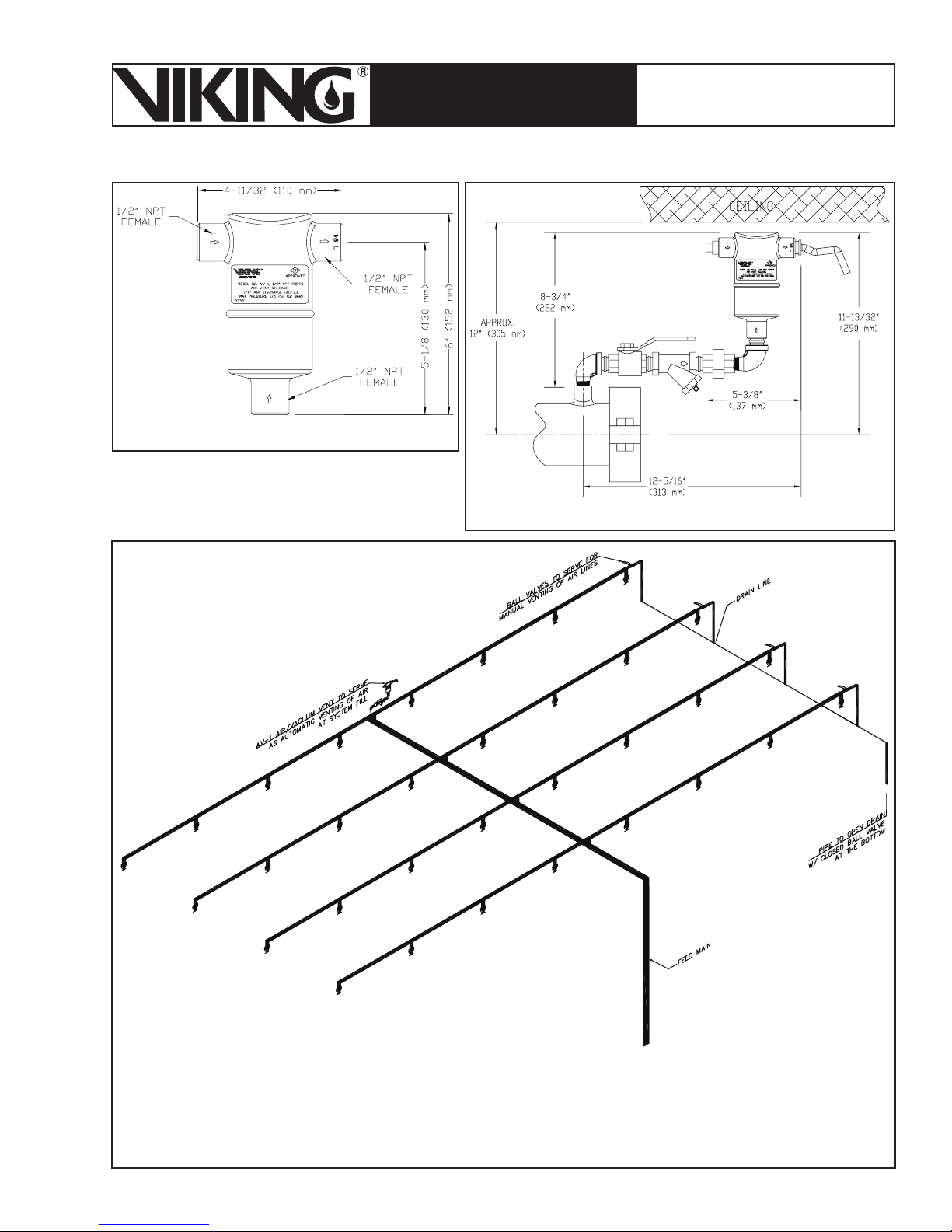
March 7, 2008
Page 55
ESFR PRE-PRIMED SINGLE
TECHNICAL DATA
INTERLOCK PREACTION
COLD STORAGE SYSTEM
The Viking Corporation, 210 N Industrial Park Road, Hastings MI 49058
Telephone: 269-945-9501 Technical Services 877-384-5464 Fax: 269-945-4495 Email: [email protected]
Figure 35 - Av-1 Dimensions
Figure 36 - Av-1 on Branch Line Pipe
Automatic air vents or ½” manual bleed valves must be installed at the highest and most remote
points of the system in order to completely vent out all air during the propylene glycol filling process.
Additional vents or ½” bleed valves shall be installed on the end of branch lines at high points. The
manual bleed valves may also be used for antifreeze testing sample points.
Figure 37 - Recommended Arrangement of AV-1 and Branch Line Drains
Page 56
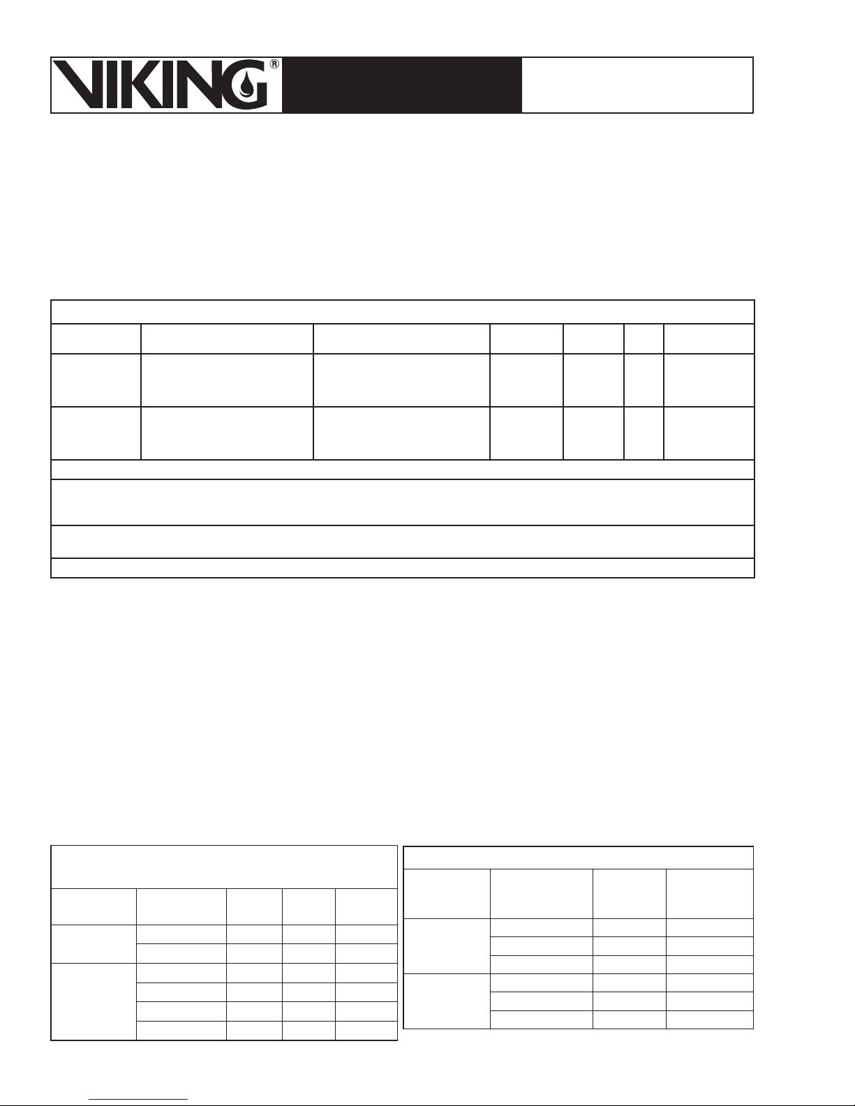
Page 56
March 7, 2008
ESFR PRE-PRIMED SINGLE
TECHNICAL DATA
INTERLOCK PREACTION
COLD STORAGE SYSTEM
The Viking Corporation, 210 N Industrial Park Road, Hastings MI 49058
Telephone: 269-945-9501 Technical Services 877-384-5464 Fax: 269-945-4495 Email: [email protected]
12. Firefi ghter Eliminator
A. Description
Viking Firefighter Eliminator C and F is a certified premixed propylene glycol/water antifreeze
solution required for use with the Viking ESFR Cold Storage System.
B. Technical Data
Table 17 - Typical Properties (Not for specification purposes)
Concentration Part Numbers Minimum use
Firefighter C 35% by volume propylene glycol
< 5% dipotassium phosphate
< 3% coloring
Firefighter F 50% by volume propylene glycol
< 5% dipotassium phosphate
< 3% coloring
For further details, see the Viking Firefighter Eliminator C Material Safety Data Sheet (pages 49e-g and 50e-g).
Environmental & Toxicological Information: Viking Firefighter Eliminator is virtually harmless to animals or plants; however, as with any sub-
stance, care should be taken to prevent discharge from entering ground water, surface water, or storm drains. Disposal of this solution should be
made in accordance with federal, state, and local regulations.
Propylene glycol/water solutions are designed to be installed on systems supplied by potable water supplies. Local authorities should be
consulted prior to draining system to storm sewers or to natural drainage areas.
Manufactured by: The Noble Company, 7300 Enterprise Dr., Spring Lake, MI U.S.A. 49456
12968-55 = 55 gallon drum
12968-275 = 275 gallon drum
12968-BULK = tanker delivery
12967-55 = 55 gallon drum
12967-275 = 275 gallon drum
12967-BULK = tanker delivery
Temperature
8 °F
(-13.3 °C)
-21 °F
(-29.4 °C)
Freeze
Point
2.4°F
(-16.4 °C)
-26 °F
(-32.2 °C)
pH Apperance
9 Fluorescent
green color
9 Fluorescent
orange color
C. Inspections, Tests and Maintenance
Field mixing of propylene glycol and site water is strictly prohibited, as the control of the mixture
cannot be assured. Improper field mixing of solution can result in reduced capability to prevent
freezing or to control a fire. Firefighter Eliminator is already premixed and ready to use.
Testing the Solution:
Antifreeze solution shall be checked semi-annually with a refractometer to detect the concen-
tration of antifreeze solution and effectiveness against freezing. Sampling shall be taken from
multiple points within the freezer system (refer to the instructions on data page 45d for fluid
sampling). When draining sample antifreeze solution from the system, be sure to shut off the
system control valve directly upstream of the Easy Riser
enter the system.
Table 18 - Solution Properties for Given
Temperatures
Solution Temperature Specific
Gravity
Firefighter 35%
Eliminator C
Firefighter 50%
Eliminator F
6 °F (-14.5 °C) 1.040 64.90 18
68 °F (20 °C) 1.033 64.46 4
-20° F (-28.9 °C) 1.085 67.70 180
-10 °F (-23.3 °C) 1.061 66.20 96
0 °F (-17.8 °C) 1.056 65.89 61
60 °F (15.6 °C) 1.041 64.96 8.13
Density
(lbs/ft3)
Viscosity
(cps)
®
Check valve so that water doesn’t
Table 19 - Propylene Glycol Refractive Index
Solution Freezing Point
Firefighter 50%
Eliminator F
Firefighter 35%
Eliminator C
25.8 °F (-32.1 °C) 48.9% 1.3892
28.3 °F (-33.5 °C) 49.9% 1.3903
-31 °F (-35.0 °C) 50.9% 1.3914
2.5 °F (-16.4 °C) 34.4% 1.3733
.9 °F (-17.3 °C) 35.5% 1.3744
-.8 °F (.18.2 °C) 36.5% 1.3756
Volume %
Propylene
Glycol
Refractive
Index
71.6 °F (22 °C)
Page 57
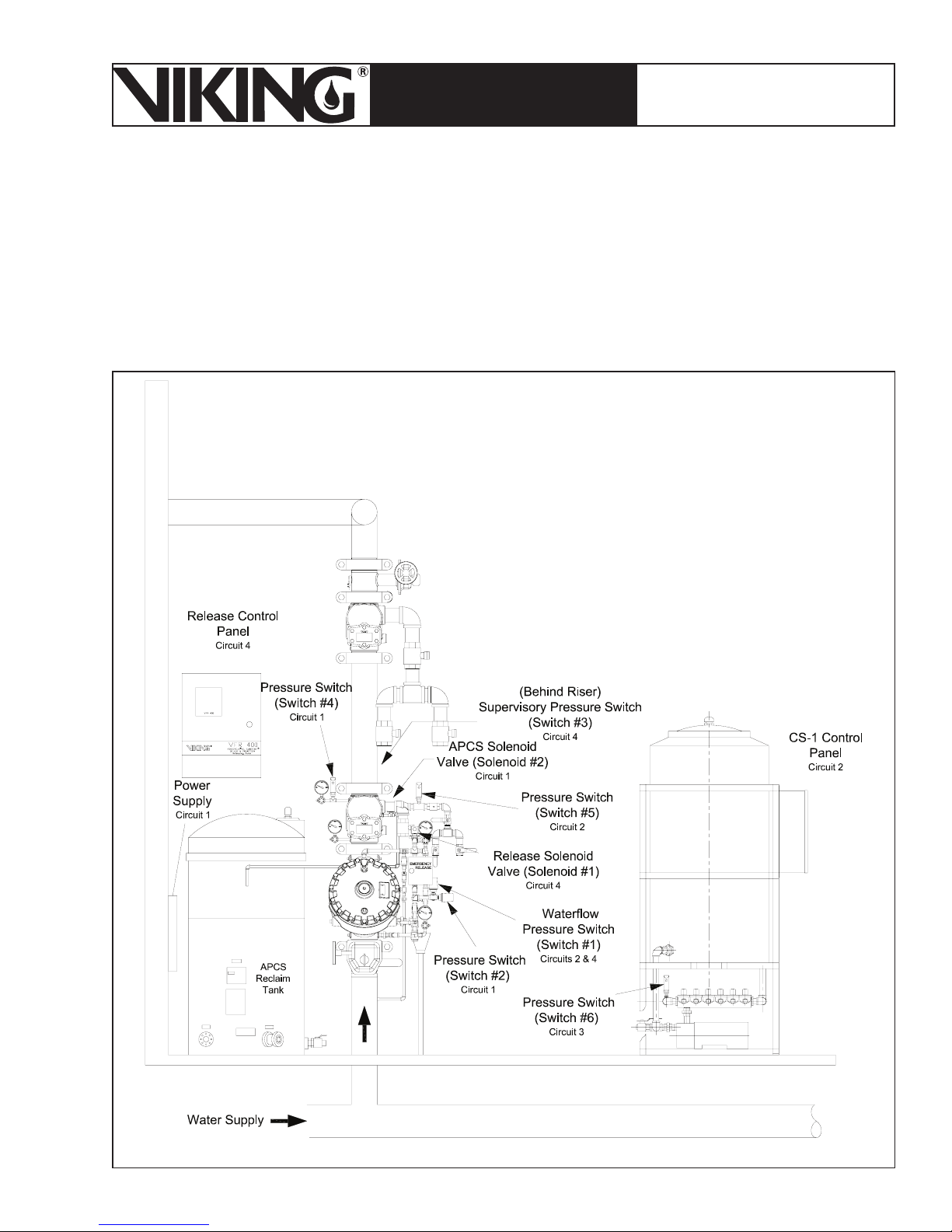
March 7, 2008
ESFR PRE-PRIMED SINGLE
TECHNICAL DATA
The Viking Corporation, 210 N Industrial Park Road, Hastings MI 49058
Telephone: 269-945-9501 Technical Services 877-384-5464 Fax: 269-945-4495 Email: [email protected]
After the CS-1 pump has restored the antifreeze solution pressure, ensure that the water supply control valve is returned to the fully open position once fluid sampling is completed. Multiple
propylene glycol/water solution test valves (refer to Figure 37) are to be installed in several
areas on the system piping for testing with a refractometer (refer to data page 45a-j for testing
requirements and procedures).
INTERLOCK PREACTION
COLD STORAGE SYSTEM
Page 57
IV. WIRING
The Electrical wiring is broken down into 4 Circuits as shown in Figure 38.
Figure 38 - Wiring Circuits
Page 58
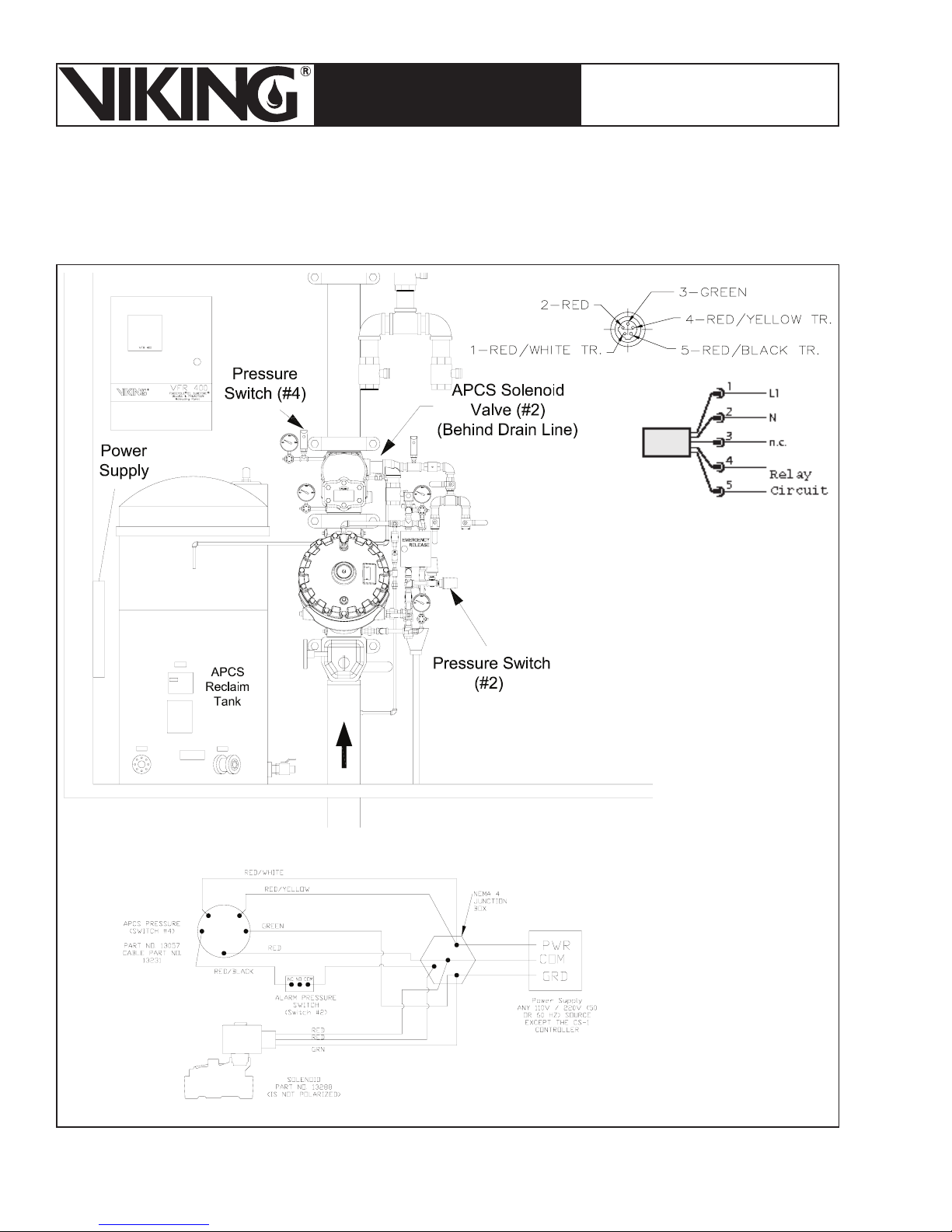
Page 58
ESFR PRE-PRIMED SINGLE
TECHNICAL DATA
The Viking Corporation, 210 N Industrial Park Road, Hastings MI 49058
Telephone: 269-945-9501 Technical Services 877-384-5464 Fax: 269-945-4495 Email: [email protected]
INTERLOCK PREACTION
COLD STORAGE SYSTEM
March 7, 2008
1. Wiring Circuit 1
Wiring circuit 1 is described in Section IV .5.A - Cold Storage Trim with Automatic Pressure Control
System.
Digital Pressure Switch Pin
Connections
Figure 39 - Circuit 1
Page 59
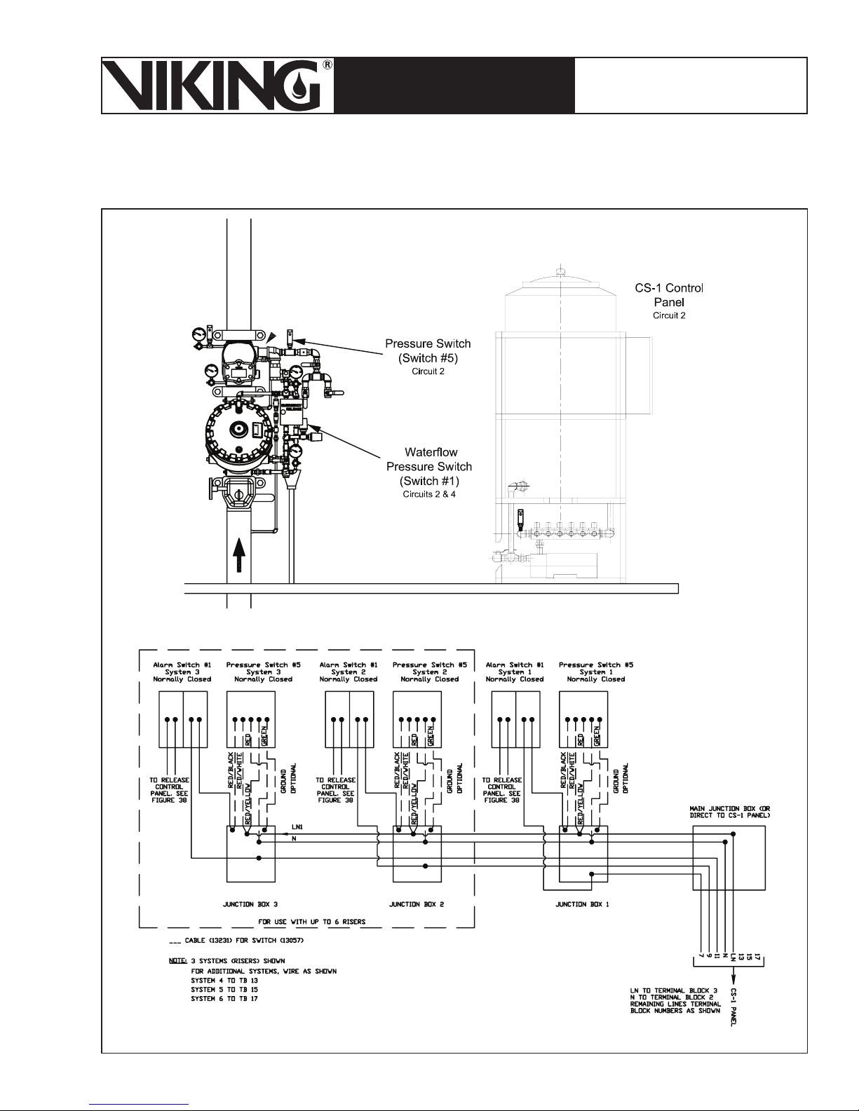
March 7, 2008
Page 59
ESFR PRE-PRIMED SINGLE
TECHNICAL DATA
INTERLOCK PREACTION
COLD STORAGE SYSTEM
The Viking Corporation, 210 N Industrial Park Road, Hastings MI 49058
Telephone: 269-945-9501 Technical Services 877-384-5464 Fax: 269-945-4495 Email: [email protected]
2. Wiring Cicuit 2
Figure 40 - Circuit 2
Page 60
Page 60
March 7, 2008
ESFR PRE-PRIMED SINGLE
TECHNICAL DATA
INTERLOCK PREACTION
COLD STORAGE SYSTEM
The Viking Corporation, 210 N Industrial Park Road, Hastings MI 49058
Telephone: 269-945-9501 Technical Services 877-384-5464 Fax: 269-945-4495 Email: [email protected]
3. Wiring Circuit 3
Wiring Circuit 3 is comprised of the CS-1 solenoid valve(s) and the CS-1 pressure switch.
There are 12 wiring diagrams in the following pages, one for each model CS-1 Tank and Pump
Package.
Table 20 - CS-1 Schematic Drawing Numbers
Drawing Number Manual Page
60Hz 50Hz 60Hz 50Hz
Single Riser 13050-1 13051-1 60-61 72-73
Two Risers 13050-2 13051-2 62-63 74-75
Three Risers 13050-3 13051-3 64-65 76-77
Four Risers 13050-4 13051-4 66-67 78-79
Five Risers 13050-5 13051-5 68-69 80-81
Six Risers 13050-6 13051-6 70-71 82-83
Page 61
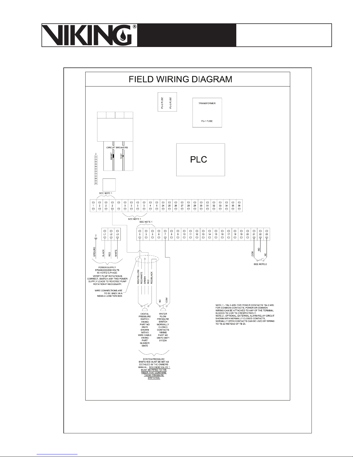
March 7, 2008
Page 61
ESFR PRE-PRIMED SINGLE
TECHNICAL DATA
INTERLOCK PREACTION
COLD STORAGE SYSTEM
The Viking Corporation, 210 N Industrial Park Road, Hastings MI 49058
Telephone: 269-945-9501 Technical Services 877-384-5464 Fax: 269-945-4495 Email: [email protected]
Figure 41a - Wiring Diagram 13050-1
60 Hz - 1 Solenoid
Page 62
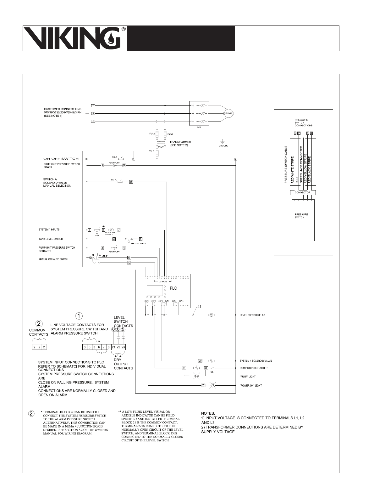
Page 62
March 7, 2008
ESFR PRE-PRIMED SINGLE
TECHNICAL DATA
INTERLOCK PREACTION
COLD STORAGE SYSTEM
The Viking Corporation, 210 N Industrial Park Road, Hastings MI 49058
Telephone: 269-945-9501 Technical Services 877-384-5464 Fax: 269-945-4495 Email: [email protected]
Figure 41b - Wiring Diagram 13050-1
60 Hz - 1 Solenoid
Page 63
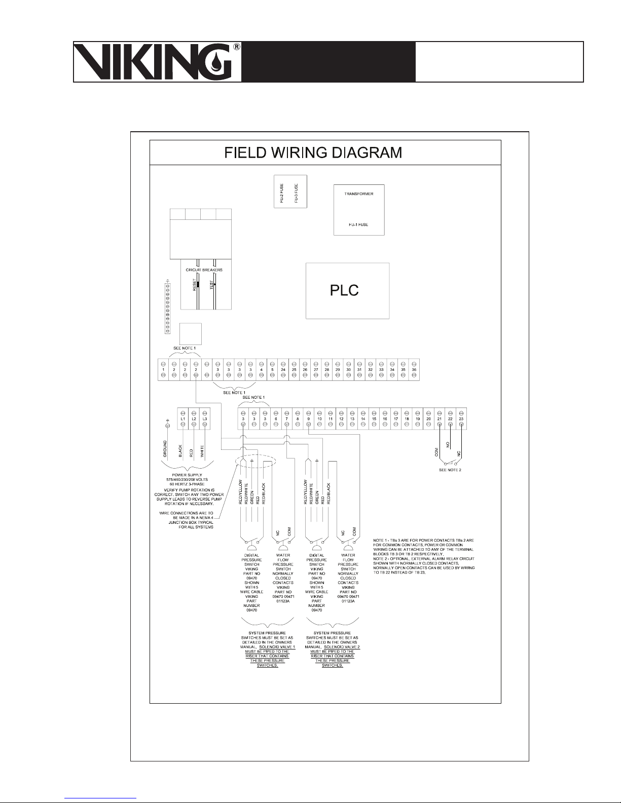
March 7, 2008
Page 63
ESFR PRE-PRIMED SINGLE
TECHNICAL DATA
INTERLOCK PREACTION
COLD STORAGE SYSTEM
The Viking Corporation, 210 N Industrial Park Road, Hastings MI 49058
Telephone: 269-945-9501 Technical Services 877-384-5464 Fax: 269-945-4495 Email: [email protected]
Figure 42a - Wiring Diagram 13050-2
60 Hz - 2 Solenoids
Page 64
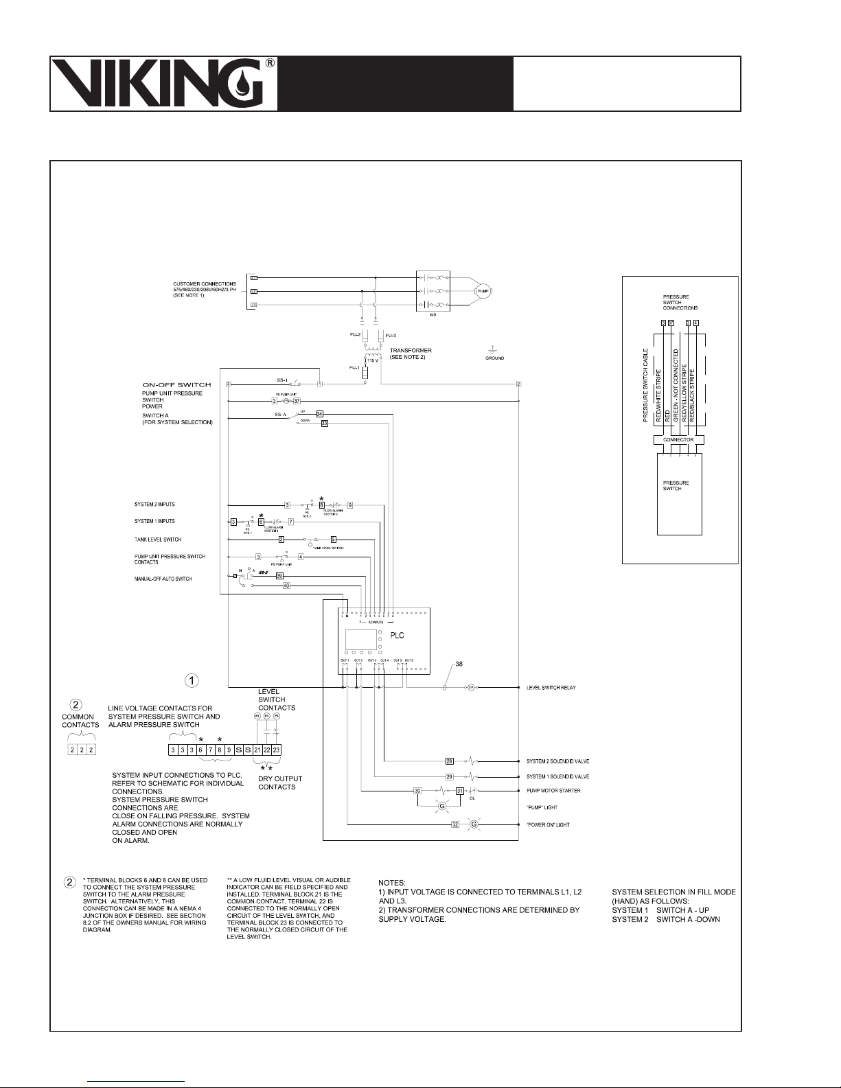
Page 64
March 7, 2008
ESFR PRE-PRIMED SINGLE
TECHNICAL DATA
INTERLOCK PREACTION
COLD STORAGE SYSTEM
The Viking Corporation, 210 N Industrial Park Road, Hastings MI 49058
Telephone: 269-945-9501 Technical Services 877-384-5464 Fax: 269-945-4495 Email: [email protected]
Figure 42b - Wiring Diagram 13050-2
60 Hz - 2 Solenoids
Page 65
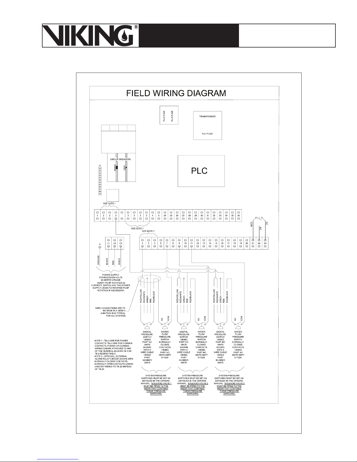
March 7, 2008
Page 65
ESFR PRE-PRIMED SINGLE
TECHNICAL DATA
INTERLOCK PREACTION
COLD STORAGE SYSTEM
The Viking Corporation, 210 N Industrial Park Road, Hastings MI 49058
Telephone: 269-945-9501 Technical Services 877-384-5464 Fax: 269-945-4495 Email: [email protected]
Figure 43a - Wiring Diagram 13050-3
60 Hz - 3 Solenoids
Page 66
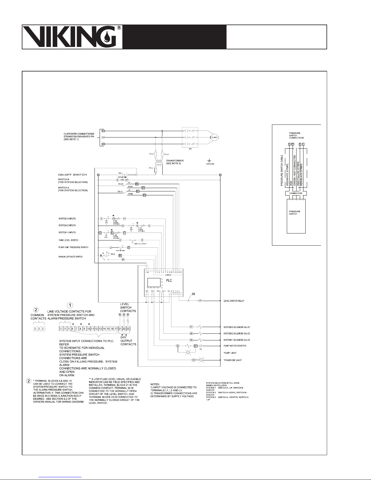
Page 66
March 7, 2008
ESFR PRE-PRIMED SINGLE
TECHNICAL DATA
INTERLOCK PREACTION
COLD STORAGE SYSTEM
The Viking Corporation, 210 N Industrial Park Road, Hastings MI 49058
Telephone: 269-945-9501 Technical Services 877-384-5464 Fax: 269-945-4495 Email: [email protected]
Figure 43b - Wiring Diagram 13050-3
60 Hz - 3 Solenoids
Page 67
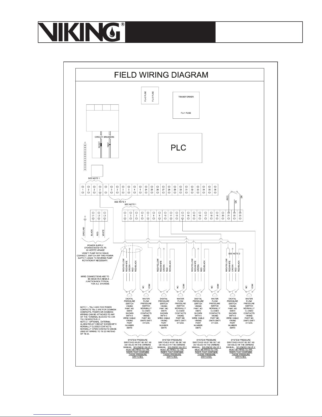
March 7, 2008
Page 67
ESFR PRE-PRIMED SINGLE
TECHNICAL DATA
INTERLOCK PREACTION
COLD STORAGE SYSTEM
The Viking Corporation, 210 N Industrial Park Road, Hastings MI 49058
Telephone: 269-945-9501 Technical Services 877-384-5464 Fax: 269-945-4495 Email: [email protected]
Figure 44a - Wiring Diagram 13050-4
60 Hz - 4 Solenoids
Page 68
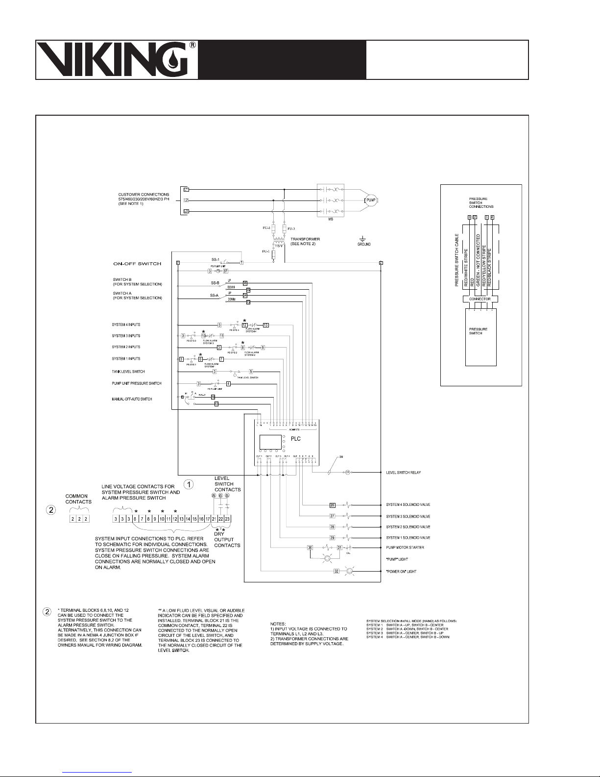
Page 68
March 7, 2008
ESFR PRE-PRIMED SINGLE
TECHNICAL DATA
INTERLOCK PREACTION
COLD STORAGE SYSTEM
The Viking Corporation, 210 N Industrial Park Road, Hastings MI 49058
Telephone: 269-945-9501 Technical Services 877-384-5464 Fax: 269-945-4495 Email: [email protected]
Figure 44b - Wiring Diagram 13050-4
60 Hz - 4 Solenoids
Page 69
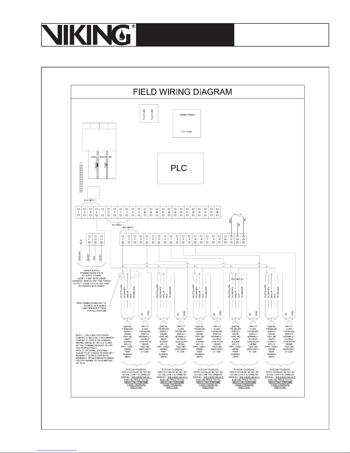
March 7, 2008
Page 69
ESFR PRE-PRIMED SINGLE
TECHNICAL DATA
INTERLOCK PREACTION
COLD STORAGE SYSTEM
The Viking Corporation, 210 N Industrial Park Road, Hastings MI 49058
Telephone: 269-945-9501 Technical Services 877-384-5464 Fax: 269-945-4495 Email: [email protected]
Figure 45a - Wiring Diagram 13050-5
60 Hz - 5 Solenoids
Page 70
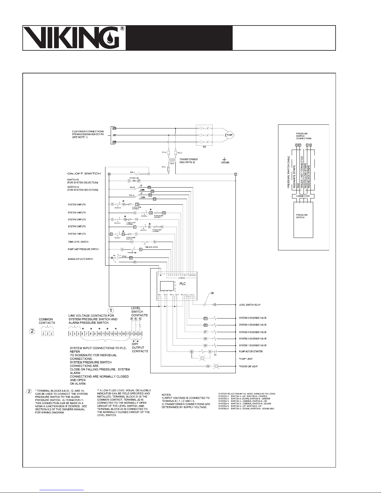
Page 70
March 7, 2008
ESFR PRE-PRIMED SINGLE
TECHNICAL DATA
INTERLOCK PREACTION
COLD STORAGE SYSTEM
The Viking Corporation, 210 N Industrial Park Road, Hastings MI 49058
Telephone: 269-945-9501 Technical Services 877-384-5464 Fax: 269-945-4495 Email: [email protected]
Figure 45b - Wiring Diagram 13050-5
60 Hz - 5 Solenoids
Page 71
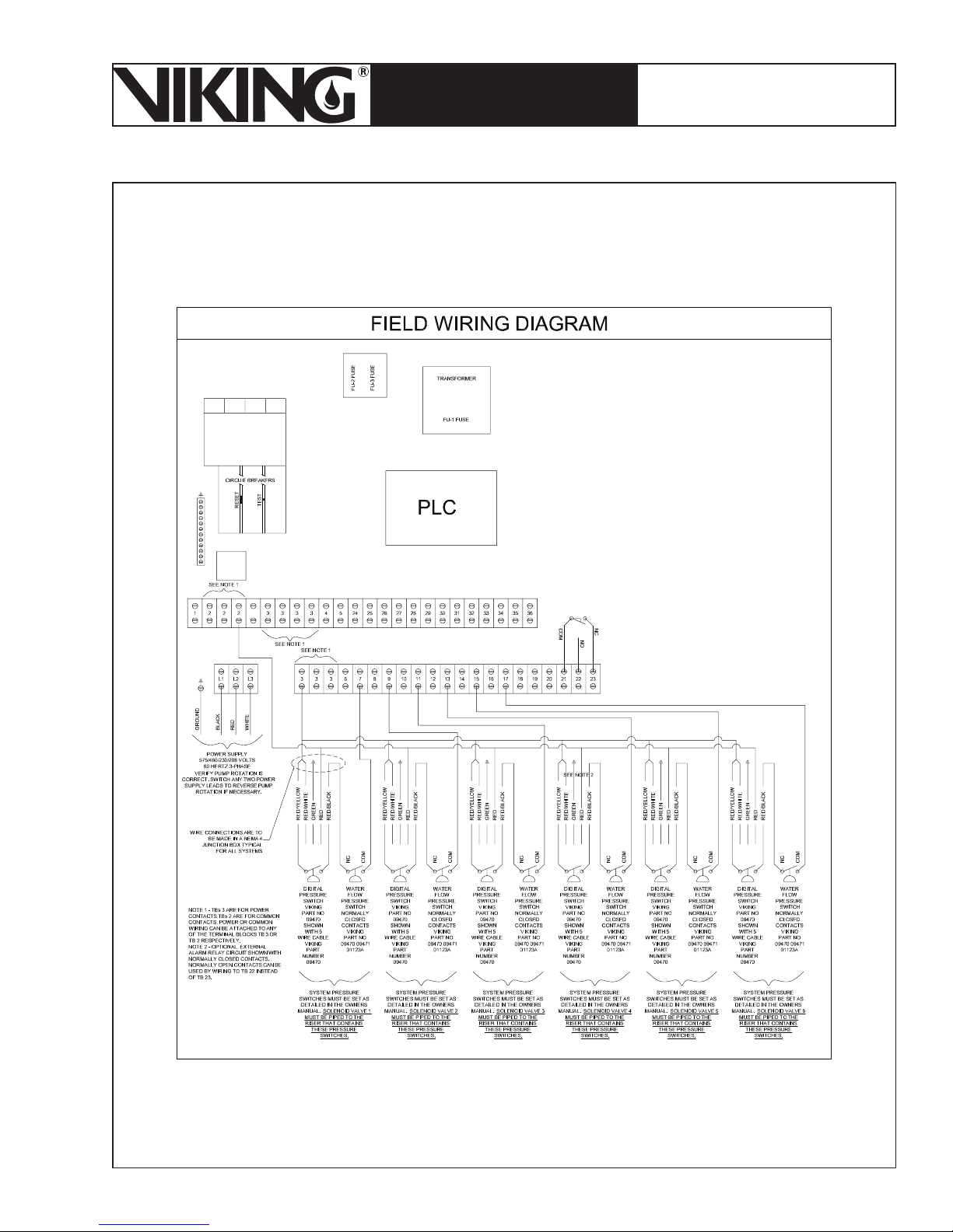
March 7, 2008
Page 71
ESFR PRE-PRIMED SINGLE
TECHNICAL DATA
INTERLOCK PREACTION
COLD STORAGE SYSTEM
The Viking Corporation, 210 N Industrial Park Road, Hastings MI 49058
Telephone: 269-945-9501 Technical Services 877-384-5464 Fax: 269-945-4495 Email: [email protected]
Figure 46a - Wiring Diagram 13050-6
60 Hz - 6 Solenoids
Page 72
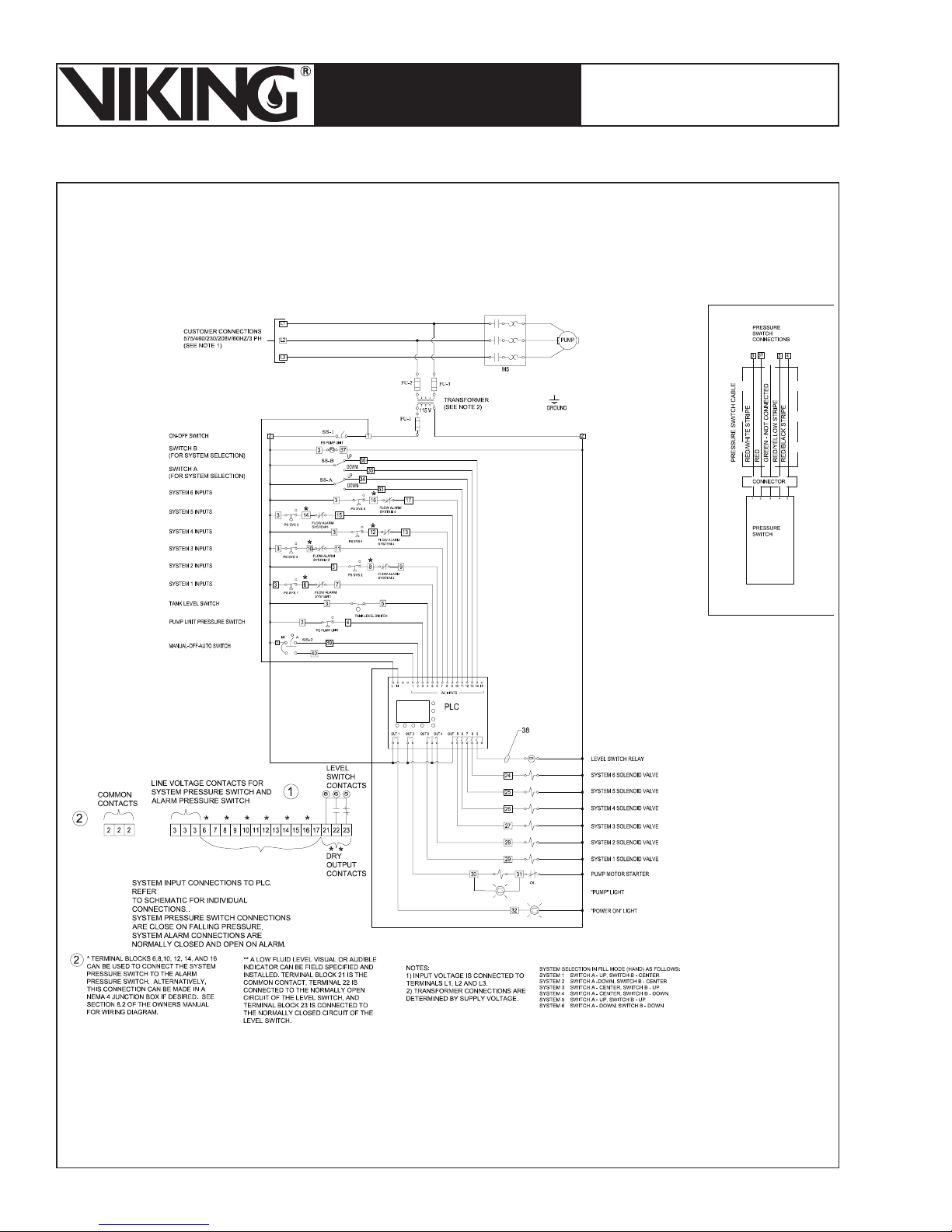
Page 72
March 7, 2008
ESFR PRE-PRIMED SINGLE
TECHNICAL DATA
INTERLOCK PREACTION
COLD STORAGE SYSTEM
The Viking Corporation, 210 N Industrial Park Road, Hastings MI 49058
Telephone: 269-945-9501 Technical Services 877-384-5464 Fax: 269-945-4495 Email: [email protected]
Figure 46b - Wiring Diagram 13050-6
60 Hz - 6 Solenoids
Page 73
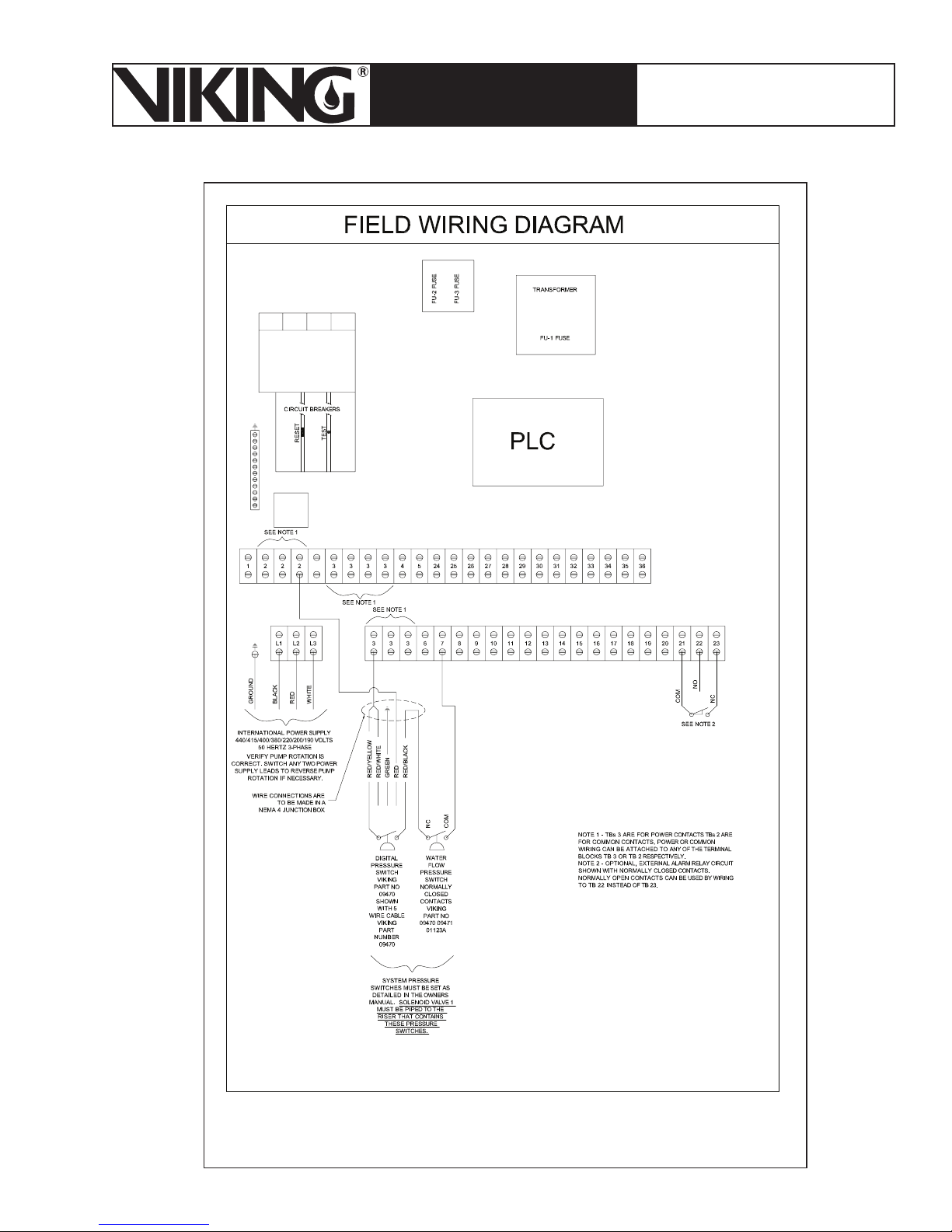
March 7, 2008
Page 73
ESFR PRE-PRIMED SINGLE
TECHNICAL DATA
INTERLOCK PREACTION
COLD STORAGE SYSTEM
The Viking Corporation, 210 N Industrial Park Road, Hastings MI 49058
Telephone: 269-945-9501 Technical Services 877-384-5464 Fax: 269-945-4495 Email: [email protected]
Figure 47a - Wiring Diagram 13051-1
50 Hz - 1 Solenoid
Page 74
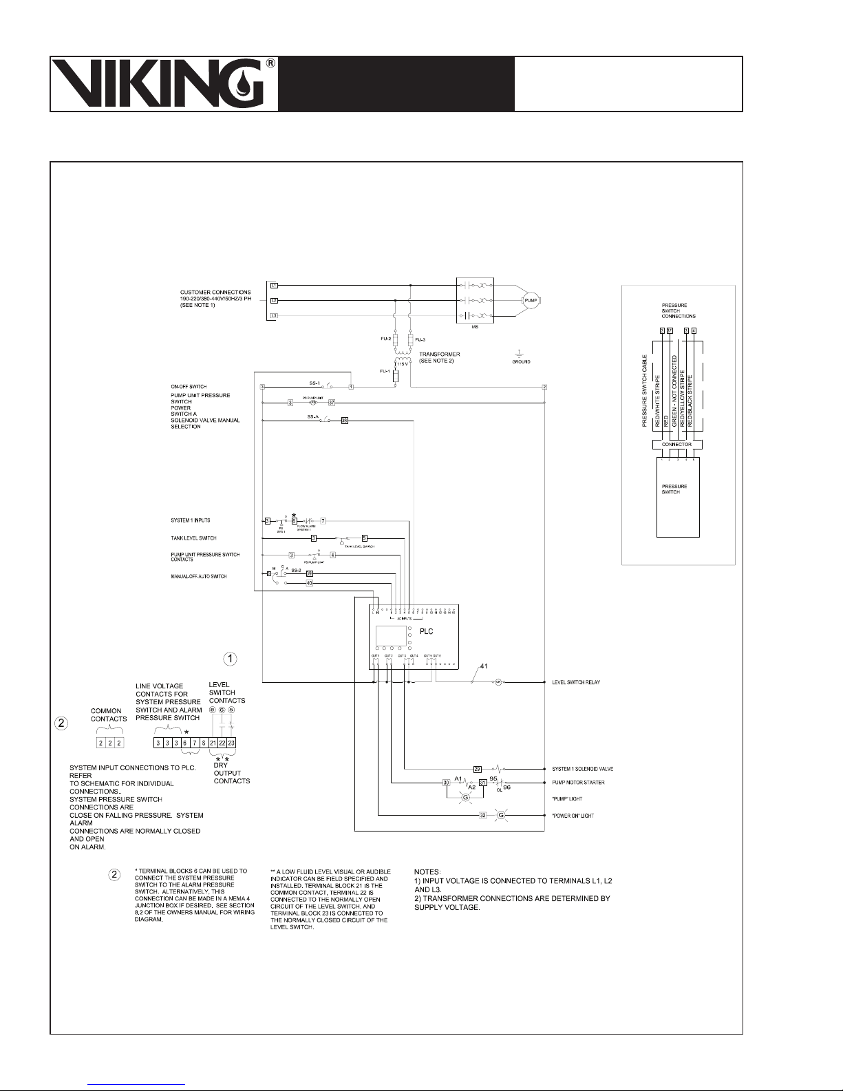
Page 74
March 7, 2008
ESFR PRE-PRIMED SINGLE
TECHNICAL DATA
INTERLOCK PREACTION
COLD STORAGE SYSTEM
The Viking Corporation, 210 N Industrial Park Road, Hastings MI 49058
Telephone: 269-945-9501 Technical Services 877-384-5464 Fax: 269-945-4495 Email: [email protected]
Figure 47b - Wiring Diagram 13051-1
50 Hz - 1 Solenoid
Page 75
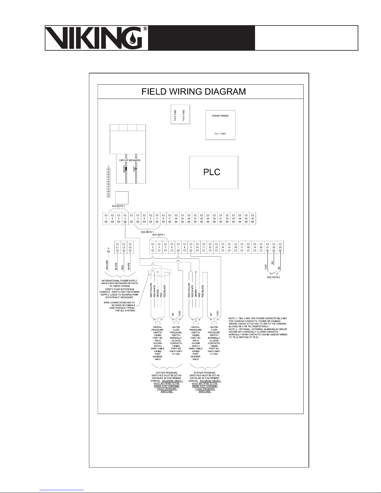
March 7, 2008
Page 75
ESFR PRE-PRIMED SINGLE
TECHNICAL DATA
INTERLOCK PREACTION
COLD STORAGE SYSTEM
The Viking Corporation, 210 N Industrial Park Road, Hastings MI 49058
Telephone: 269-945-9501 Technical Services 877-384-5464 Fax: 269-945-4495 Email: [email protected]
Figure 48a - Wiring Diagram 13051-2
50 Hz - 2 Solenoids
Page 76
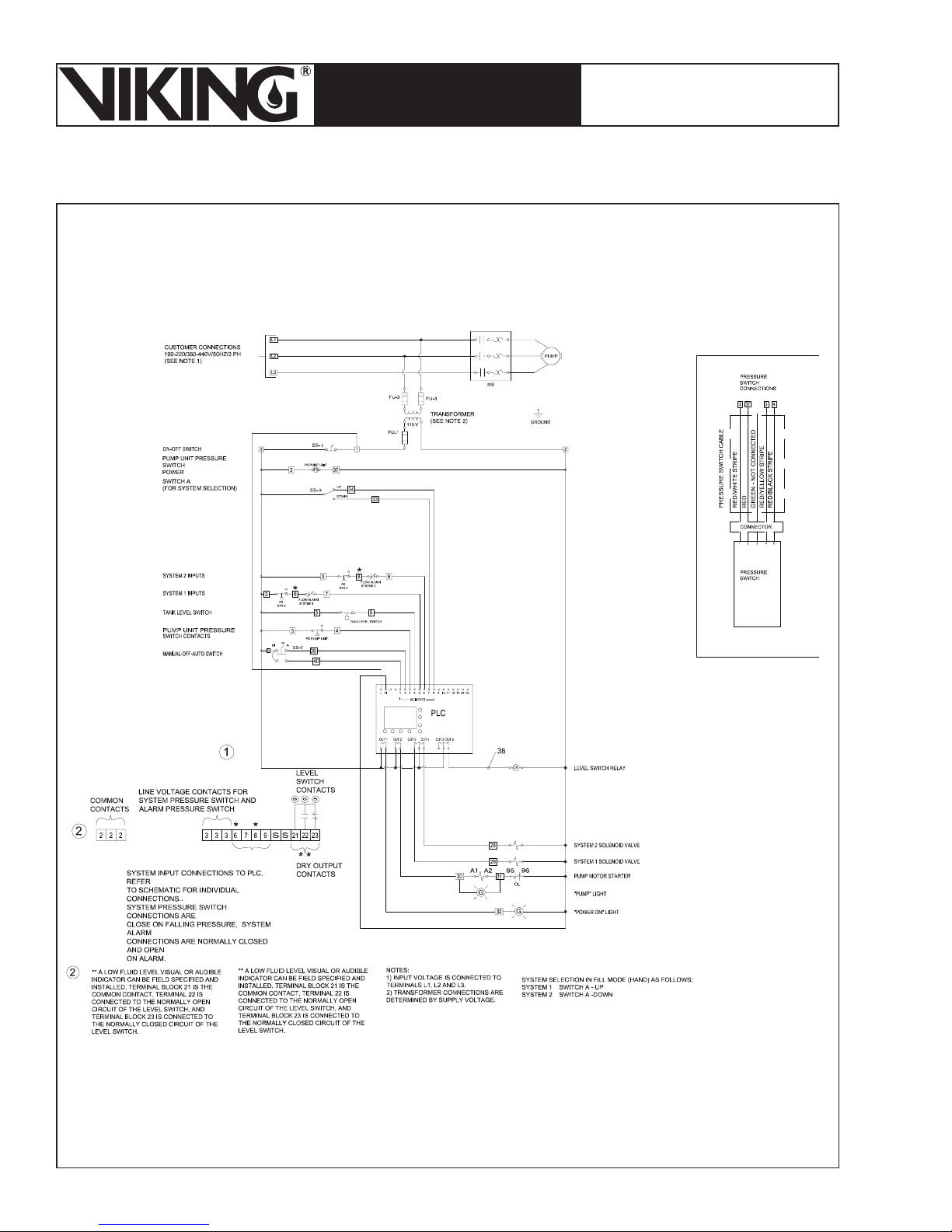
Page 76
March 7, 2008
ESFR PRE-PRIMED SINGLE
TECHNICAL DATA
INTERLOCK PREACTION
COLD STORAGE SYSTEM
The Viking Corporation, 210 N Industrial Park Road, Hastings MI 49058
Telephone: 269-945-9501 Technical Services 877-384-5464 Fax: 269-945-4495 Email: [email protected]
Figure 48b - Wiring Diagram 13051-2
50 Hz - 2 Solenoids
Page 77
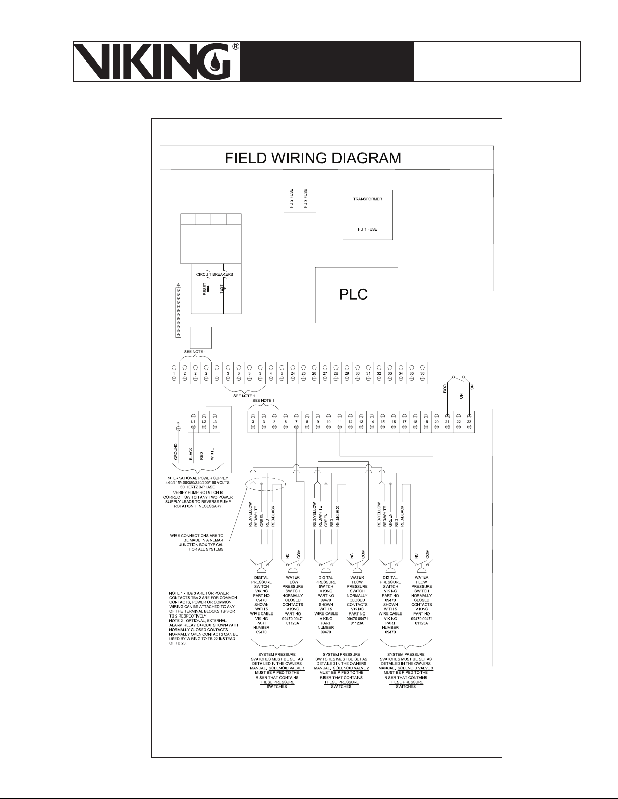
March 7, 2008
Page 77
ESFR PRE-PRIMED SINGLE
TECHNICAL DATA
INTERLOCK PREACTION
COLD STORAGE SYSTEM
The Viking Corporation, 210 N Industrial Park Road, Hastings MI 49058
Telephone: 269-945-9501 Technical Services 877-384-5464 Fax: 269-945-4495 Email: [email protected]
Figure 49a - Wiring Diagram 13051-3
50 Hz - 3 Solenoids
Page 78
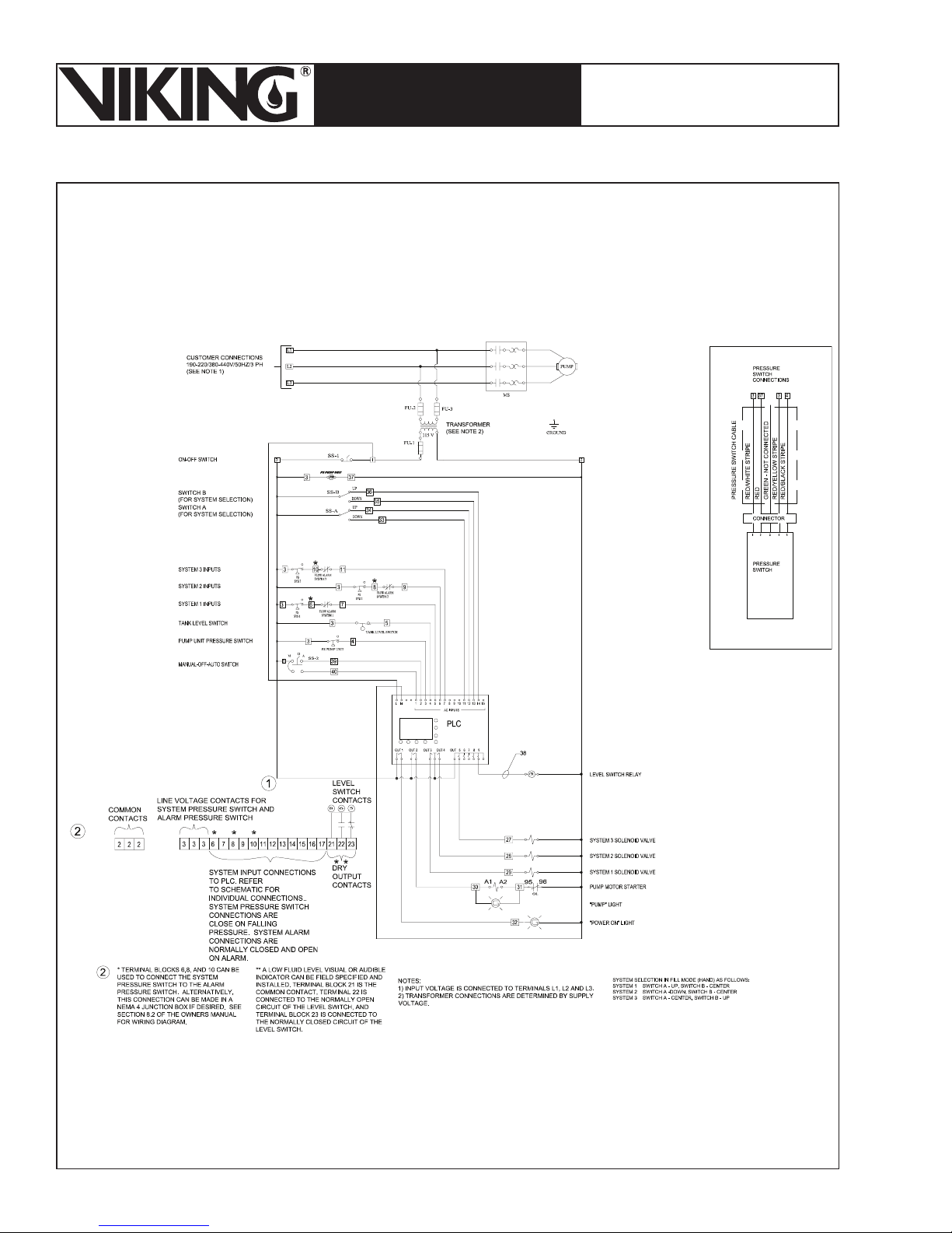
Page 78
March 7, 2008
ESFR PRE-PRIMED SINGLE
TECHNICAL DATA
INTERLOCK PREACTION
COLD STORAGE SYSTEM
The Viking Corporation, 210 N Industrial Park Road, Hastings MI 49058
Telephone: 269-945-9501 Technical Services 877-384-5464 Fax: 269-945-4495 Email: [email protected]
Figure 49b - Wiring Diagram 13051-3
50 Hz - 3 Solenoids
Page 79
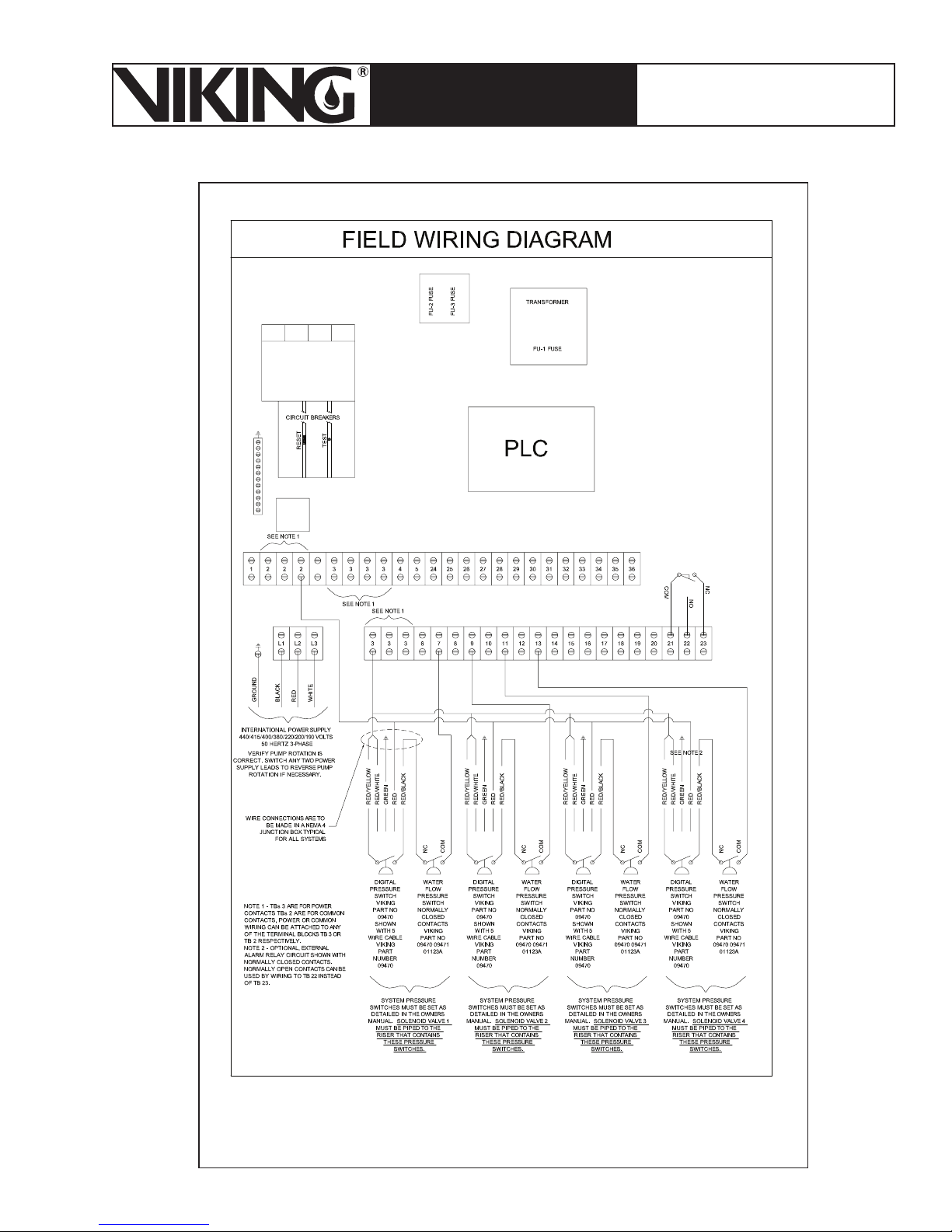
March 7, 2008
Page 79
ESFR PRE-PRIMED SINGLE
TECHNICAL DATA
INTERLOCK PREACTION
COLD STORAGE SYSTEM
The Viking Corporation, 210 N Industrial Park Road, Hastings MI 49058
Telephone: 269-945-9501 Technical Services 877-384-5464 Fax: 269-945-4495 Email: [email protected]
Figure 50a - Wiring Diagram 13051-4
50 Hz - 4 Solenoids
Page 80
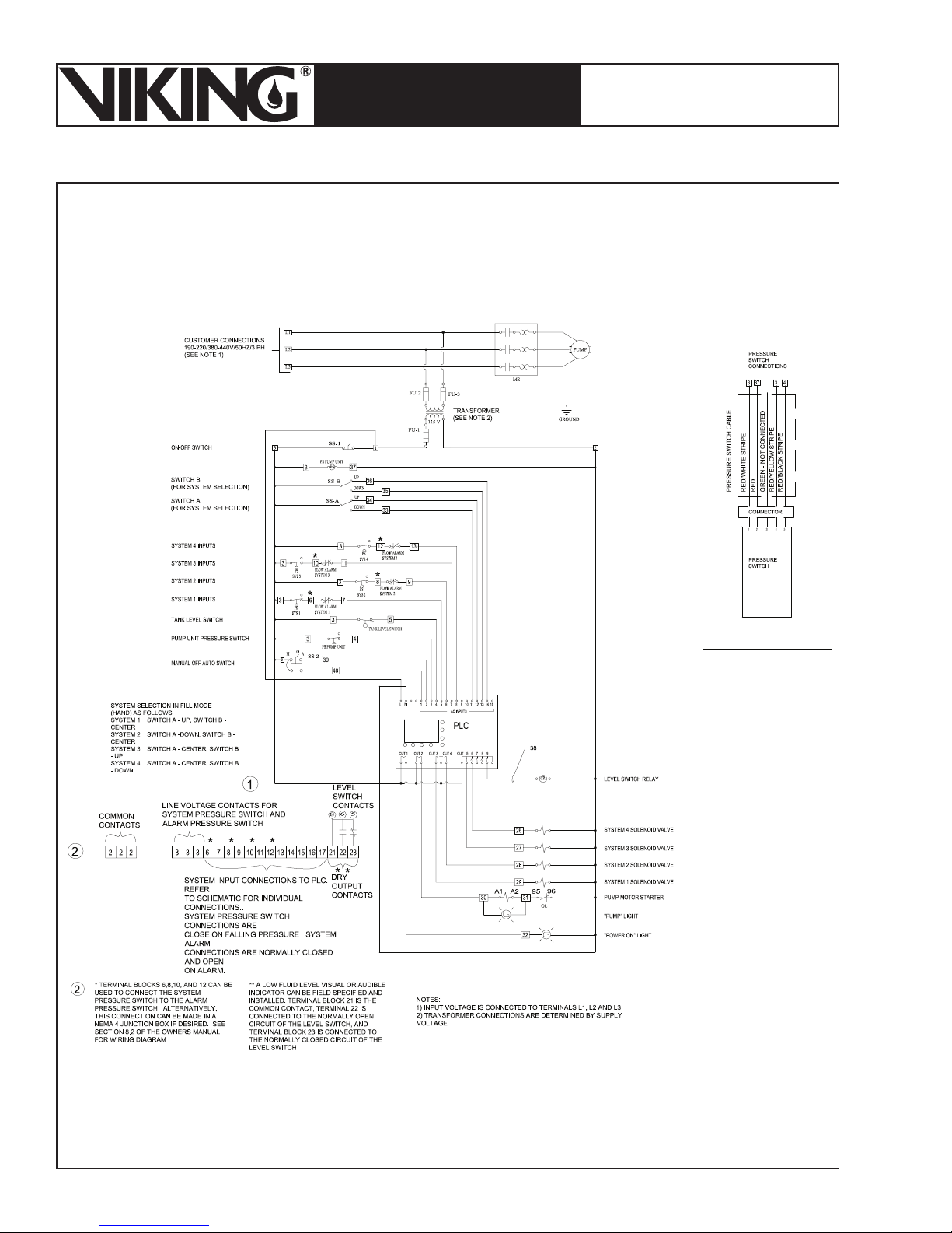
Page 80
March 7, 2008
ESFR PRE-PRIMED SINGLE
TECHNICAL DATA
INTERLOCK PREACTION
COLD STORAGE SYSTEM
The Viking Corporation, 210 N Industrial Park Road, Hastings MI 49058
Telephone: 269-945-9501 Technical Services 877-384-5464 Fax: 269-945-4495 Email: [email protected]
Figure 50b - Wiring Diagram 13051-4
50 Hz - 4 Solenoids
Page 81
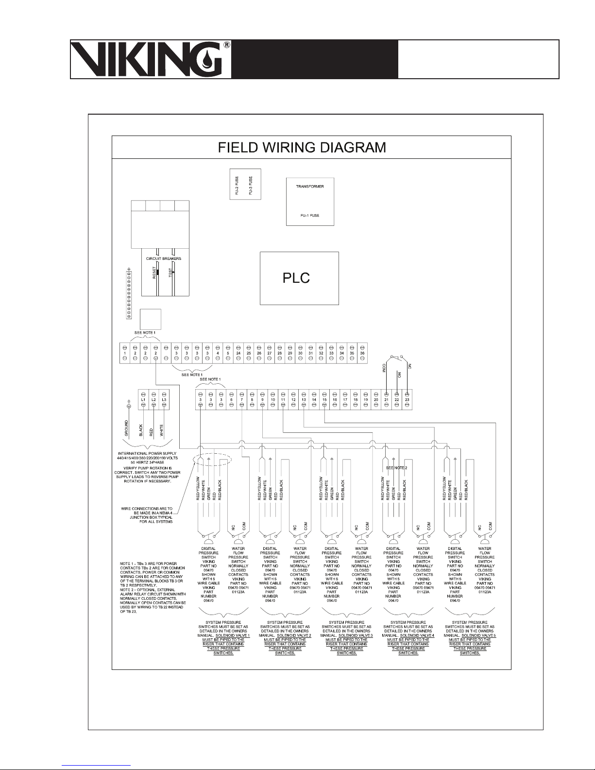
March 7, 2008
Page 81
ESFR PRE-PRIMED SINGLE
TECHNICAL DATA
INTERLOCK PREACTION
COLD STORAGE SYSTEM
The Viking Corporation, 210 N Industrial Park Road, Hastings MI 49058
Telephone: 269-945-9501 Technical Services 877-384-5464 Fax: 269-945-4495 Email: [email protected]
Figure 51a - Wiring Diagram 13051-5
50 Hz - 5 Solenoids
Page 82
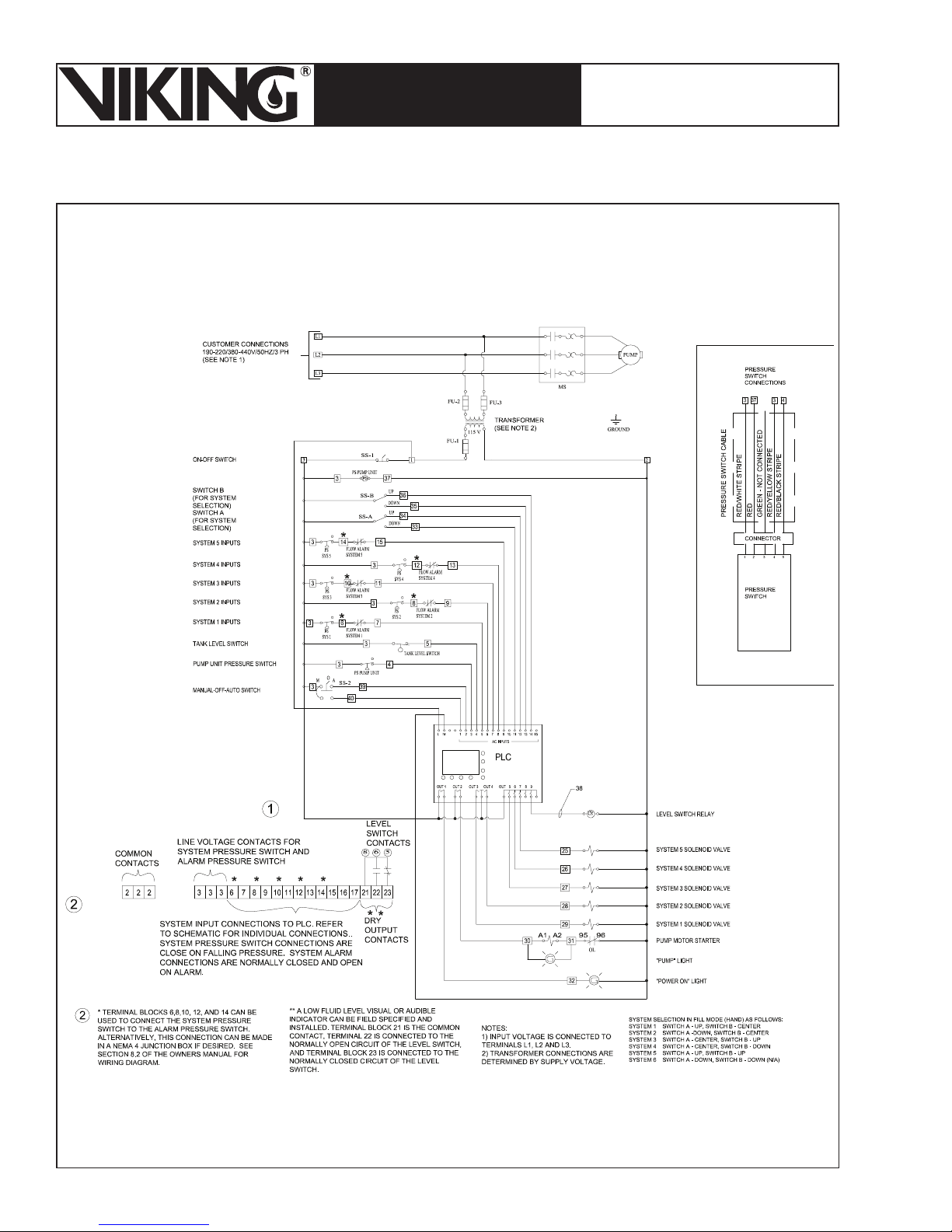
Page 82
March 7, 2008
ESFR PRE-PRIMED SINGLE
TECHNICAL DATA
INTERLOCK PREACTION
COLD STORAGE SYSTEM
The Viking Corporation, 210 N Industrial Park Road, Hastings MI 49058
Telephone: 269-945-9501 Technical Services 877-384-5464 Fax: 269-945-4495 Email: [email protected]
Figure 51b - Wiring Diagram 13051-5
50 Hz - 5 Solenoids
Page 83
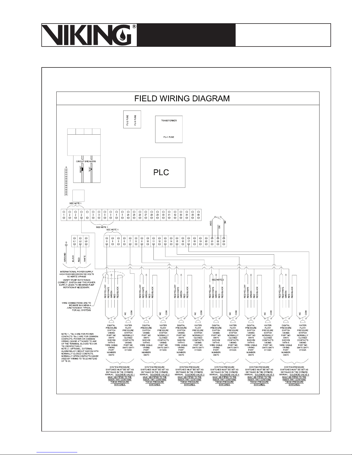
March 7, 2008
Page 83
ESFR PRE-PRIMED SINGLE
TECHNICAL DATA
INTERLOCK PREACTION
COLD STORAGE SYSTEM
The Viking Corporation, 210 N Industrial Park Road, Hastings MI 49058
Telephone: 269-945-9501 Technical Services 877-384-5464 Fax: 269-945-4495 Email: [email protected]
Figure 52a - Wiring Diagram 13051-6
50 Hz - 6 Solenoids
Page 84
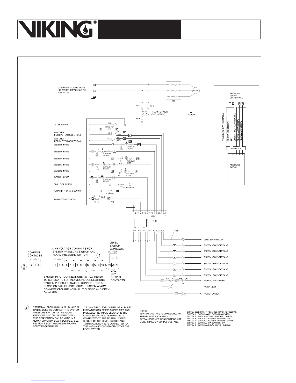
Page 84
March 7, 2008
ESFR PRE-PRIMED SINGLE
TECHNICAL DATA
INTERLOCK PREACTION
COLD STORAGE SYSTEM
The Viking Corporation, 210 N Industrial Park Road, Hastings MI 49058
Telephone: 269-945-9501 Technical Services 877-384-5464 Fax: 269-945-4495 Email: [email protected]
Figure 52b - Wiring Diagram 13051-6
50 Hz - 6 Solenoids
Page 85
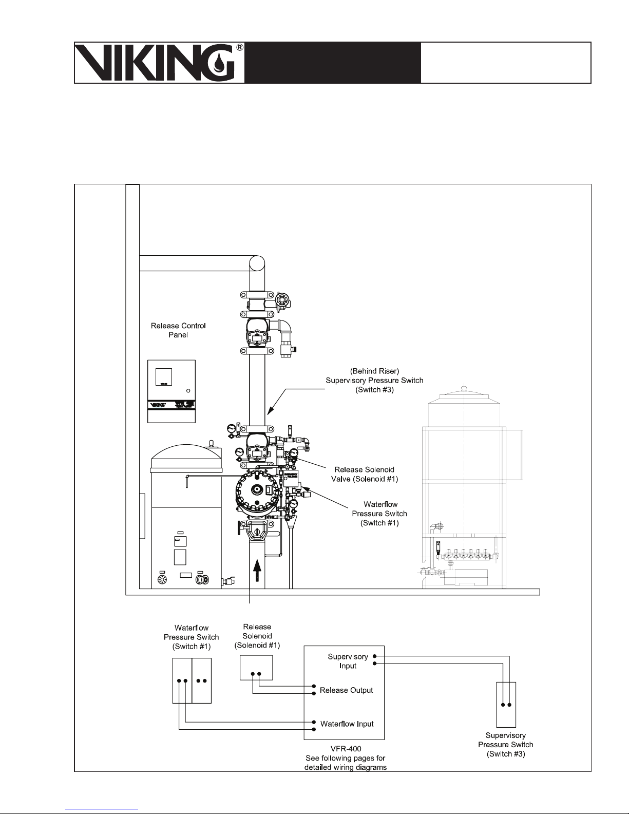
March 7, 2008
Page 85
ESFR PRE-PRIMED SINGLE
TECHNICAL DATA
INTERLOCK PREACTION
COLD STORAGE SYSTEM
The Viking Corporation, 210 N Industrial Park Road, Hastings MI 49058
Telephone: 269-945-9501 Technical Services 877-384-5464 Fax: 269-945-4495 Email: [email protected]
4. Wiring Circuit 4
See pages 86-89.
Figure 53 - Circuit 4
Page 86
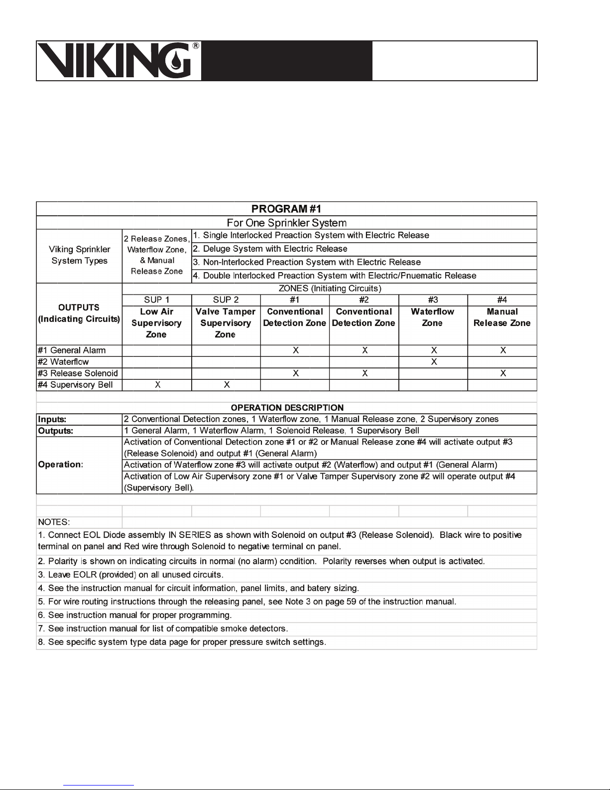
Page 86
March 7, 2008
ESFR PRE-PRIMED SINGLE
TECHNICAL DATA
INTERLOCK PREACTION
COLD STORAGE SYSTEM
The Viking Corporation, 210 N Industrial Park Road, Hastings MI 49058
Telephone: 269-945-9501 Technical Services 877-384-5464 Fax: 269-945-4495 Email: [email protected]
Page 87
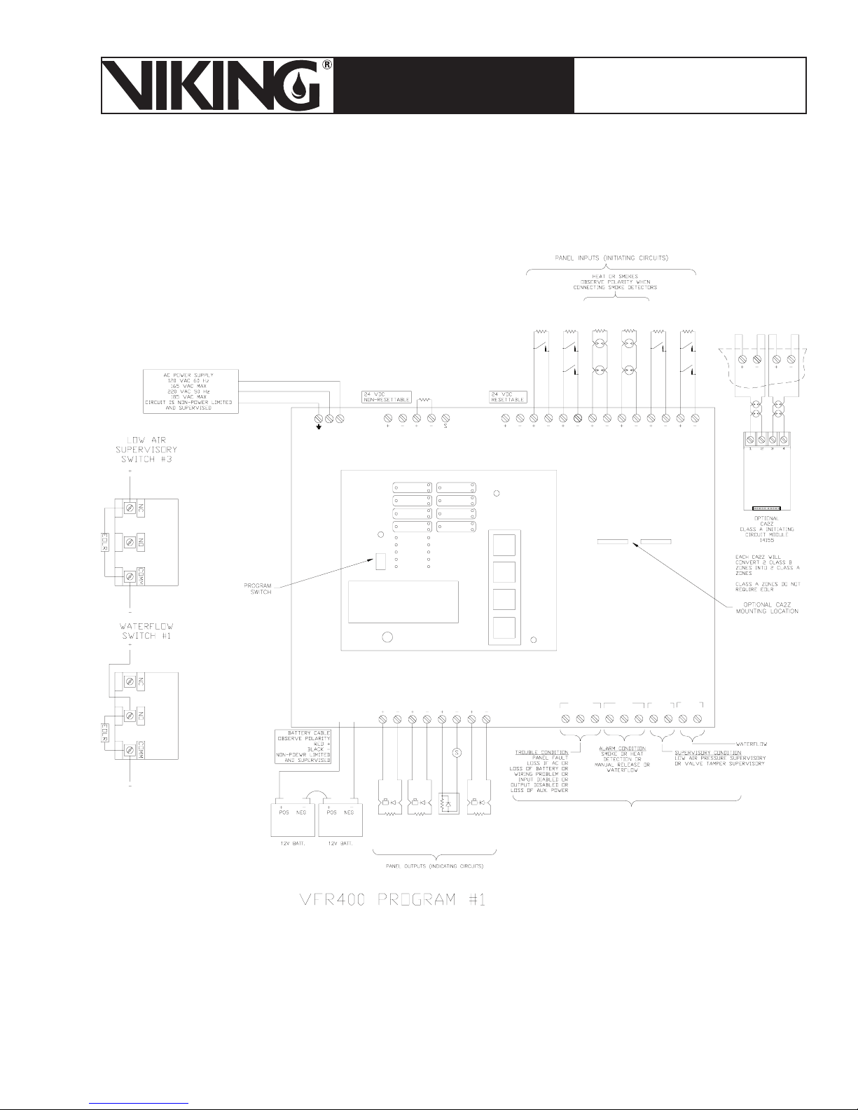
March 7, 2008
VFR-400
Page 87
ESFR PRE-PRIMED SINGLE
TECHNICAL DATA
INTERLOCK PREACTION
COLD STORAGE SYSTEM
The Viking Corporation, 210 N Industrial Park Road, Hastings MI 49058
Telephone: 269-945-9501 Technical Services 877-384-5464 Fax: 269-945-4495 Email: [email protected]
HOT - BLACK
NEUTRAL - WHITE
EARTH GROUND - GR EEN
NL
BAT+
PROGRAM
RUN
120 OHM
RS-48524 VNR DC
RED OUTPUT LED STEADY: ABORT
ZONE 1
OUTPUT 1
ZONE 2
OUTPUT 2
ZONE 3
OUTPUT 3
ZONE 4
AC POWER
POWER TBL
SYSTEM TBL
SUP TBL
GROUND
FAULT
VIEWING AN GLE
OUTPUT 4
SUP 1/ABORT
SUPERVIS O RY 2
COMMON ALARM
ALARM SILENCE
STEADY: DISCHARGED
FLASHING: PRE DISCHARGE
SELECT
FUNCTION
PROGRAM
MODE
SET
AUX. POWER
24VR DC
LOW AIR
PRESSURE
SUPERVISORY
SWITCH
09472
EOLR
5.1K
SUP 1
RUN
MODE
SCROLL-UP
BUZZER SILENCE
SCROLL-DOWN
BUZZER SILENCE
SIGNAL SILENCE
SYSTEM RESET
VALVE
TAMPER
SUPERVISORY
EOLR
5.1K
SUP 2
CONVENTIONAL
DETECTION
EOLR
5.1K
CONVENTIONAL
DETECTION
EOLR
5.1K
ZONE 2ZONE 1
WATER
FLOW
SWITCH
09470
EOLR
5.1K
ZONE 3
MANUAL
RELEASE
STATION
EOLR
5.1K
ZONE 4
ZONE 1
ZONE 2
OUTPUT 2 OUTPUT 3 OUTPUT 4
OUTPUT 1
BAT-
TROUBLE SUPV
COM
ALARM
WTRFLW
NOCOMNCNCNONONOCOMCOM
Figure 54 - Wiring Diagram for VFR-400
BLACK
RED
BLACK
BLACK
5.1K
EOLR
GENERAL
ALARM
RED
WATERFLOW
RED
BLACK
RED
5.1K
EOLR
EOL
DIODE
ASSY
RELEASE
SOLENOID
BLACK
5.1K
EOLR
SUPERVISORY
BELL
RED
RELAY CONTACT S
DRY CONTACTS RA TED AT 3A, 30VDC
Page 88
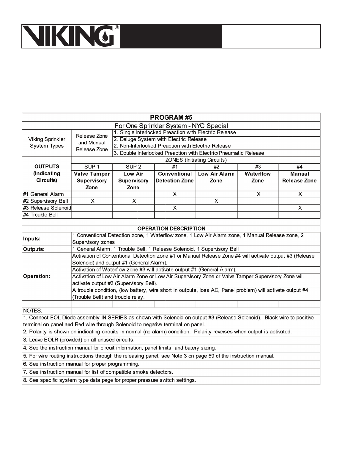
Page 88
March 7, 2008
ESFR PRE-PRIMED SINGLE
TECHNICAL DATA
INTERLOCK PREACTION
COLD STORAGE SYSTEM
The Viking Corporation, 210 N Industrial Park Road, Hastings MI 49058
Telephone: 269-945-9501 Technical Services 877-384-5464 Fax: 269-945-4495 Email: [email protected]
Page 89
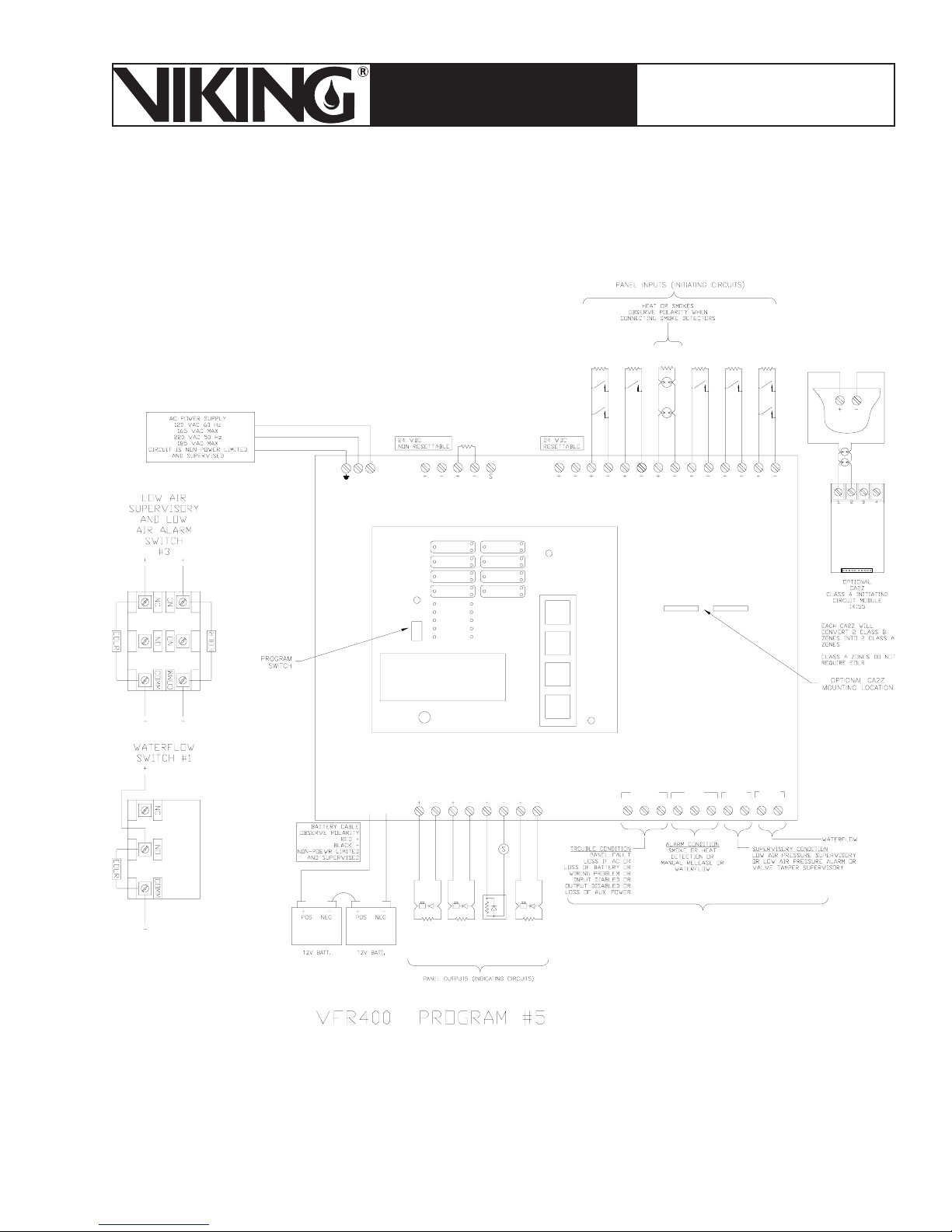
March 7, 2008
VFR-400
Page 89
ESFR PRE-PRIMED SINGLE
TECHNICAL DATA
INTERLOCK PREACTION
COLD STORAGE SYSTEM
The Viking Corporation, 210 N Industrial Park Road, Hastings MI 49058
Telephone: 269-945-9501 Technical Services 877-384-5464 Fax: 269-945-4495 Email: [email protected]
HOT - BLACK
NEUTRAL - WHIT E
EARTH GROUND - GREEN
NL
PROGRAM
RUN
120 OHM
RS-48524 VNR DC
RED OUTPUT LED STEADY: ABORT
ZONE 1
ZONE 2
ZONE 3
ZONE 4
AC POWER
POWER TBL
SYSTEM TBL
SUP TBL
GROUND
FAULT
VIEWING ANGLE
OUTPUT 1
OUTPUT 2
OUTPUT 3
OUTPUT 4
SUP 1/ABORT
SUPERVISORY 2
COMMON ALARM
ALARM SILENCE
STEADY: DISCHARGED
FLASHING: PRE-
DISCHARGE
SELECT
FUNCTION
PROGRAM
MODE
SET
AUX. POWER
24VR DC
VALVE
TAMPER
SUPERVISORY
EOLR
SUP 1
RUN
MODE
SCROLL-UP
BUZZER SILENCE
SCROLL-DOWN
BUZZER SILENCE
SIGNAL SILENCE
SYSTEM RESET
5.1K
LOW AIR
PRESSURE
SUPERVISORY
SWITCH
09473
EOLR
5.1K
SUP 2
CONVENTIONAL
DETECTION
EOLR
5.1K
LOW AIR
PRESSURE
ALARM
SWITCH
09473
EOLR
5.1K
ZONE 2ZONE 1
WATER
FLOW
SWITCH
09470
EOLR
5.1K
ZONE 3
MANUAL
RELEASE
STATION
EOLR
5.1K
ZONE 4
ZONE 1
TROUBLE SUPV
COM
DRY CONTACTS RATED AT 3A, 30VDC
BAT+
RED
BAT-
OUTPUT 1
OUTPUT 2 OUTPUT 3 OUTPUT 4
BLACK
BLACK
EOLR
BELL
RED
EOL
DIODE
ASSY
RELEASE
SOLENOID
BLACK
5.1K
EOLR
TROUBLE
BELL
RED
RED
5.1K
BLACK
5.1K
EOLR
GENERAL
ALARM
BLACK
RED
SUPERVISORY
Figure 55 - Wiring Diagram for VFR-400
Special NYC
ALARM
RELAY CONTACTS
WTRFLW
NOCOMNCNCNONONOCOMCOM
Page 90
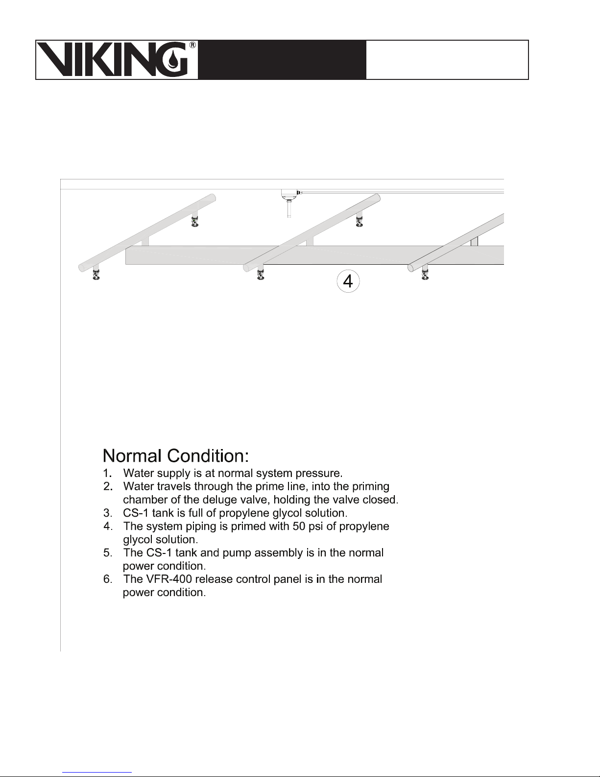
Page 90
March 7, 2008
ESFR PRE-PRIMED SINGLE
TECHNICAL DATA
INTERLOCK PREACTION
COLD STORAGE SYSTEM
The Viking Corporation, 210 N Industrial Park Road, Hastings MI 49058
Telephone: 269-945-9501 Technical Services 877-384-5464 Fax: 269-945-4495 Email: [email protected]
V. SYSTEM OPERATION
Page 91
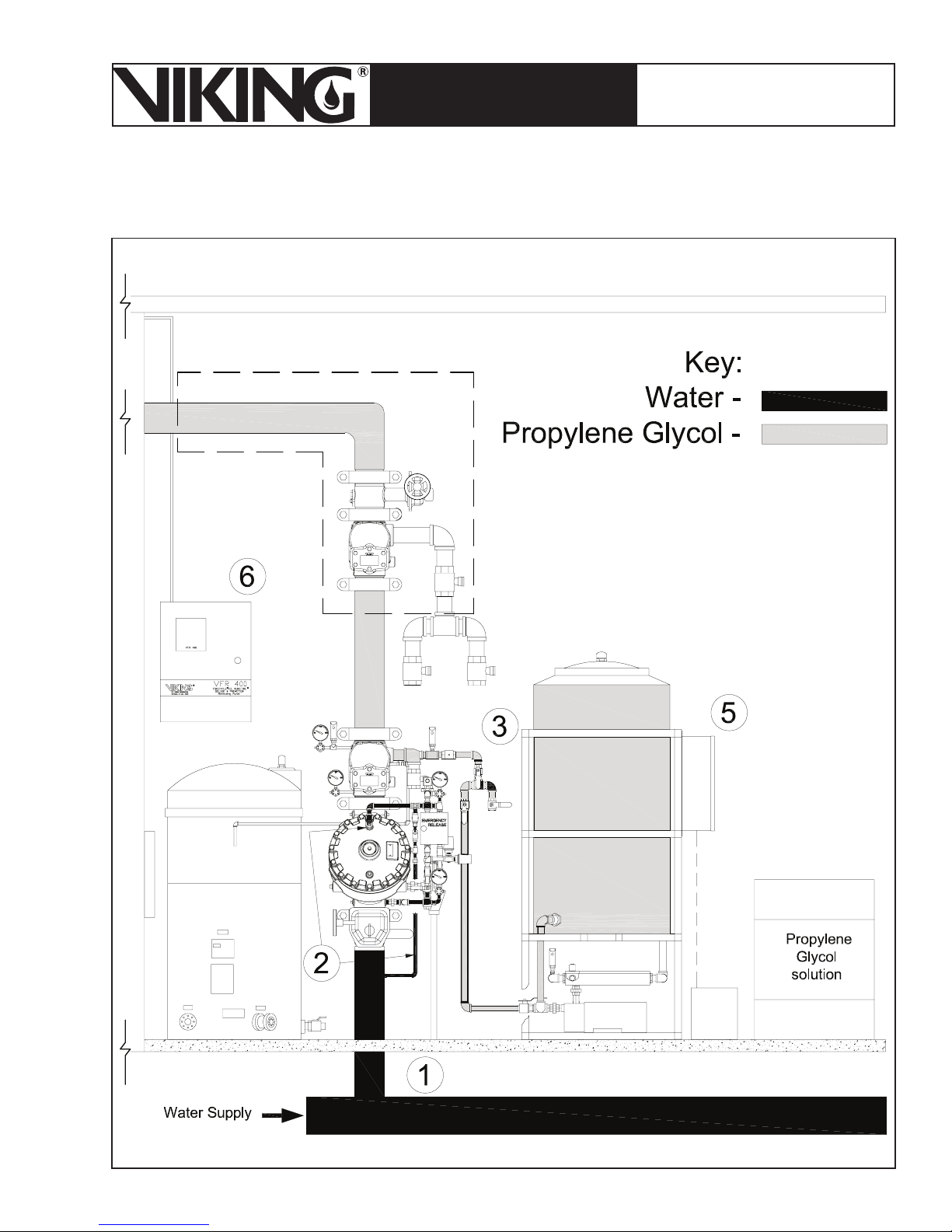
March 7, 2008
Page 91
ESFR PRE-PRIMED SINGLE
TECHNICAL DATA
INTERLOCK PREACTION
COLD STORAGE SYSTEM
The Viking Corporation, 210 N Industrial Park Road, Hastings MI 49058
Telephone: 269-945-9501 Technical Services 877-384-5464 Fax: 269-945-4495 Email: [email protected]
Page 92
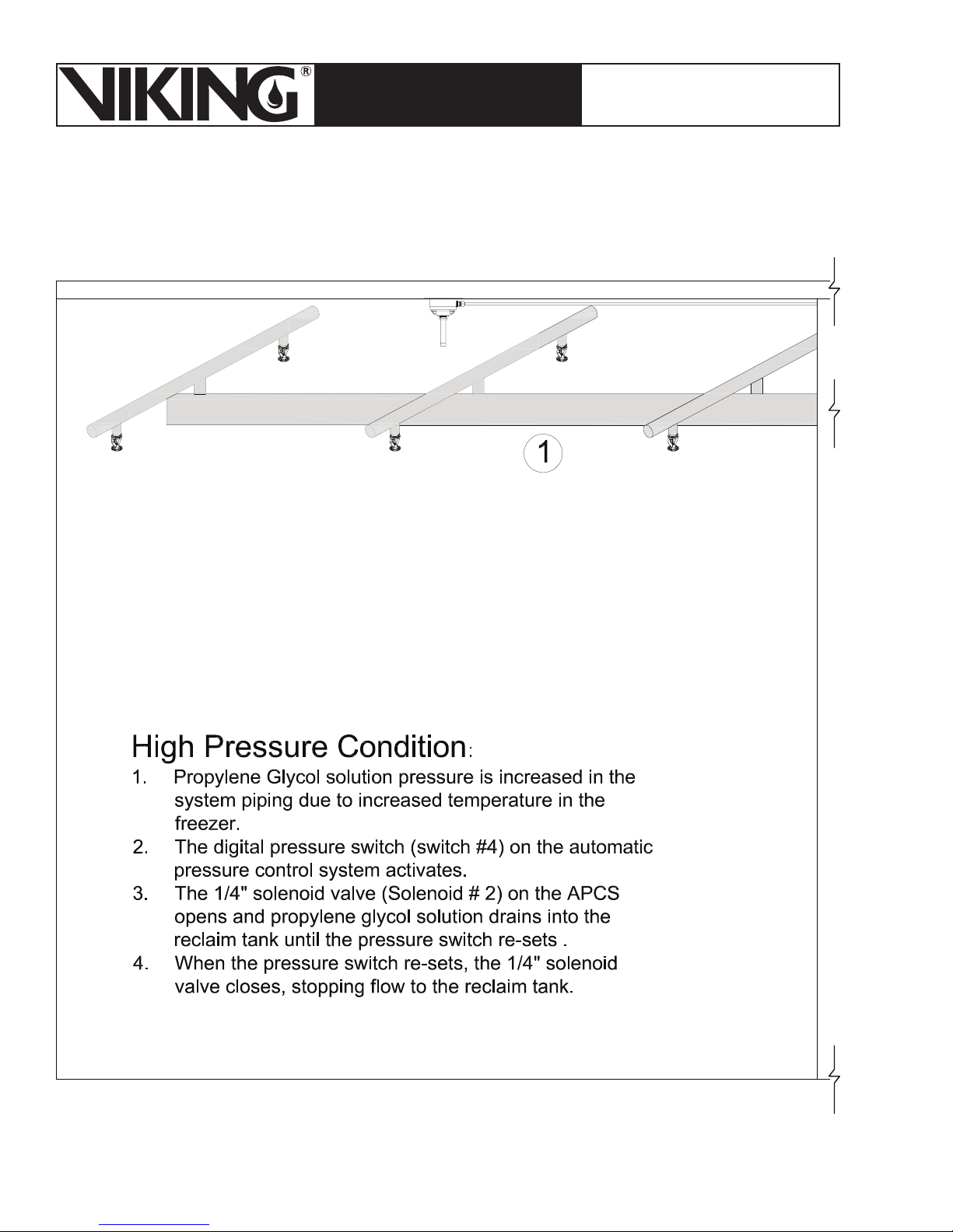
Page 92
March 7, 2008
ESFR PRE-PRIMED SINGLE
TECHNICAL DATA
INTERLOCK PREACTION
COLD STORAGE SYSTEM
The Viking Corporation, 210 N Industrial Park Road, Hastings MI 49058
Telephone: 269-945-9501 Technical Services 877-384-5464 Fax: 269-945-4495 Email: [email protected]
Page 93
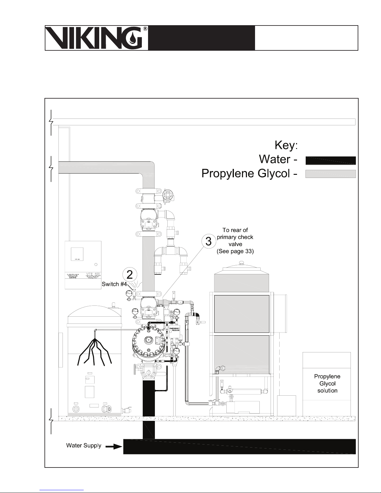
March 7, 2008
Page 93
ESFR PRE-PRIMED SINGLE
TECHNICAL DATA
INTERLOCK PREACTION
COLD STORAGE SYSTEM
The Viking Corporation, 210 N Industrial Park Road, Hastings MI 49058
Telephone: 269-945-9501 Technical Services 877-384-5464 Fax: 269-945-4495 Email: [email protected]
Page 94
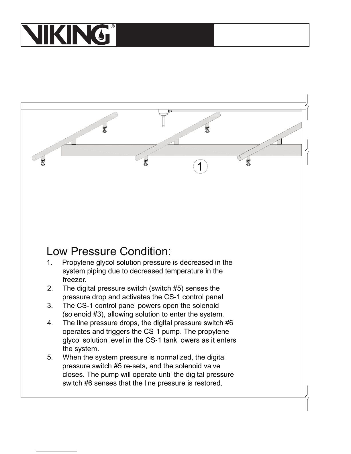
Page 94
March 7, 2008
ESFR PRE-PRIMED SINGLE
TECHNICAL DATA
INTERLOCK PREACTION
COLD STORAGE SYSTEM
The Viking Corporation, 210 N Industrial Park Road, Hastings MI 49058
Telephone: 269-945-9501 Technical Services 877-384-5464 Fax: 269-945-4495 Email: [email protected]
Page 95
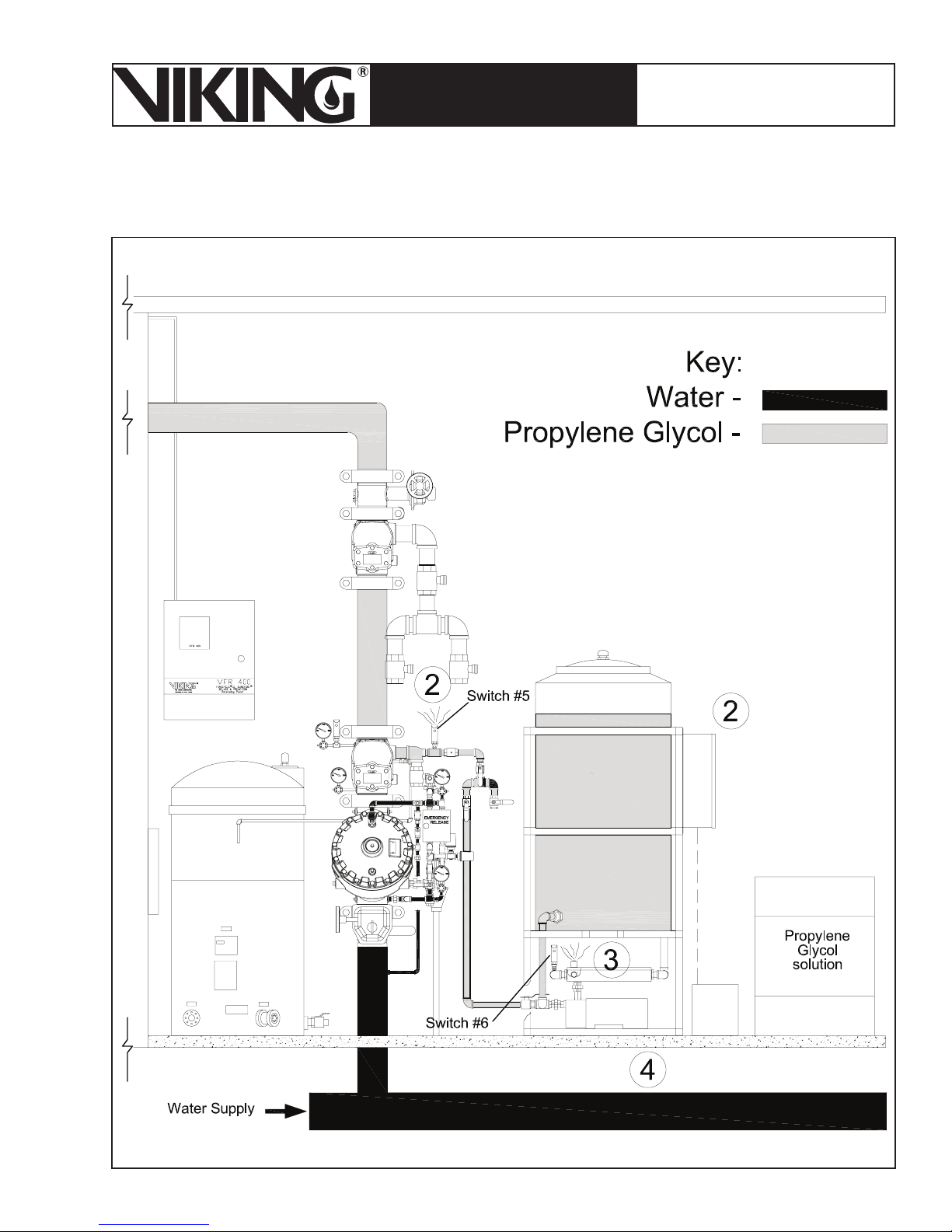
March 7, 2008
Page 95
ESFR PRE-PRIMED SINGLE
TECHNICAL DATA
INTERLOCK PREACTION
COLD STORAGE SYSTEM
The Viking Corporation, 210 N Industrial Park Road, Hastings MI 49058
Telephone: 269-945-9501 Technical Services 877-384-5464 Fax: 269-945-4495 Email: [email protected]
Page 96
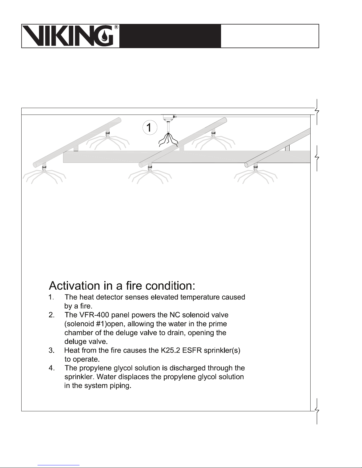
Page 96
March 7, 2008
ESFR PRE-PRIMED SINGLE
TECHNICAL DATA
INTERLOCK PREACTION
COLD STORAGE SYSTEM
The Viking Corporation, 210 N Industrial Park Road, Hastings MI 49058
Telephone: 269-945-9501 Technical Services 877-384-5464 Fax: 269-945-4495 Email: [email protected]
Page 97
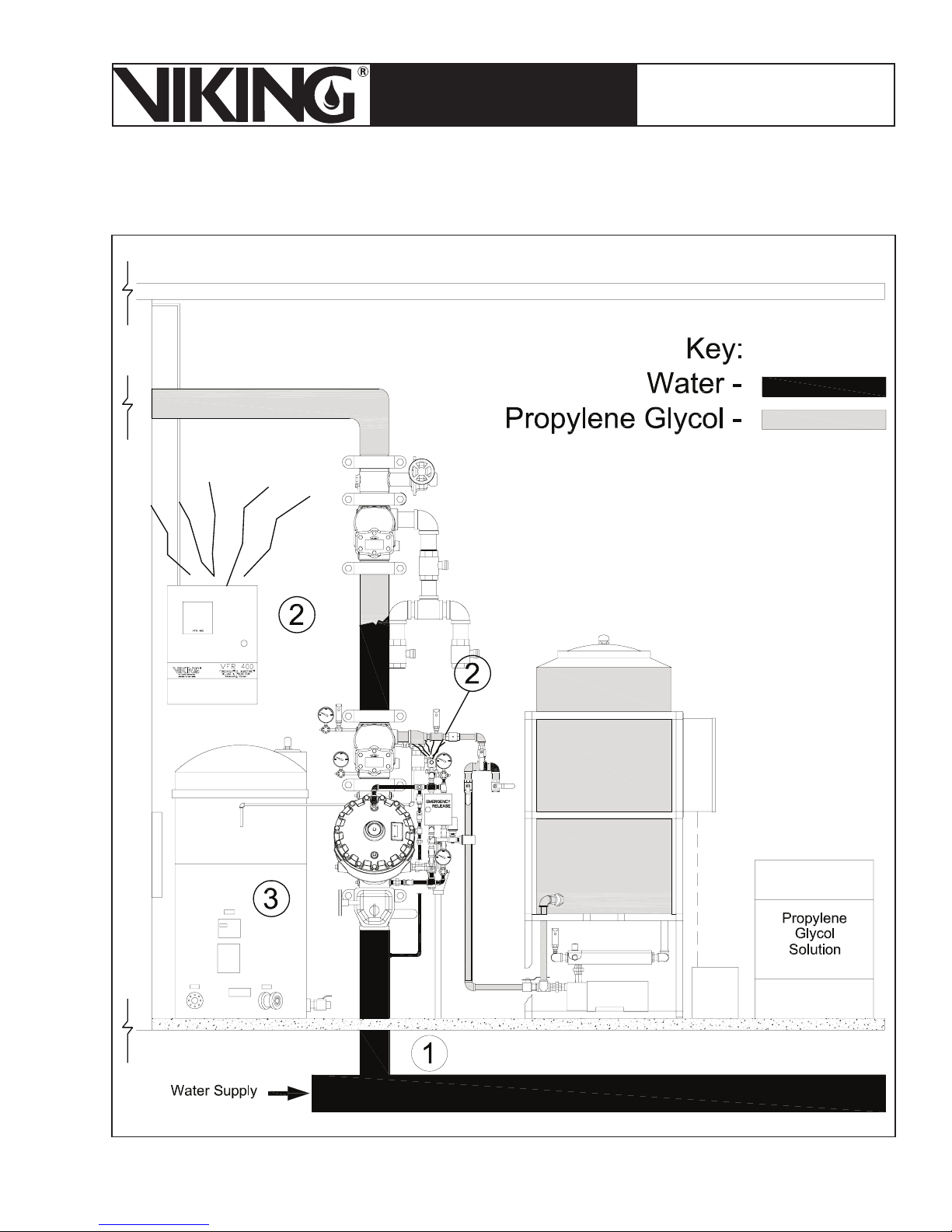
March 7, 2008
Page 97
ESFR PRE-PRIMED SINGLE
TECHNICAL DATA
INTERLOCK PREACTION
COLD STORAGE SYSTEM
The Viking Corporation, 210 N Industrial Park Road, Hastings MI 49058
Telephone: 269-945-9501 Technical Services 877-384-5464 Fax: 269-945-4495 Email: [email protected]
Page 98
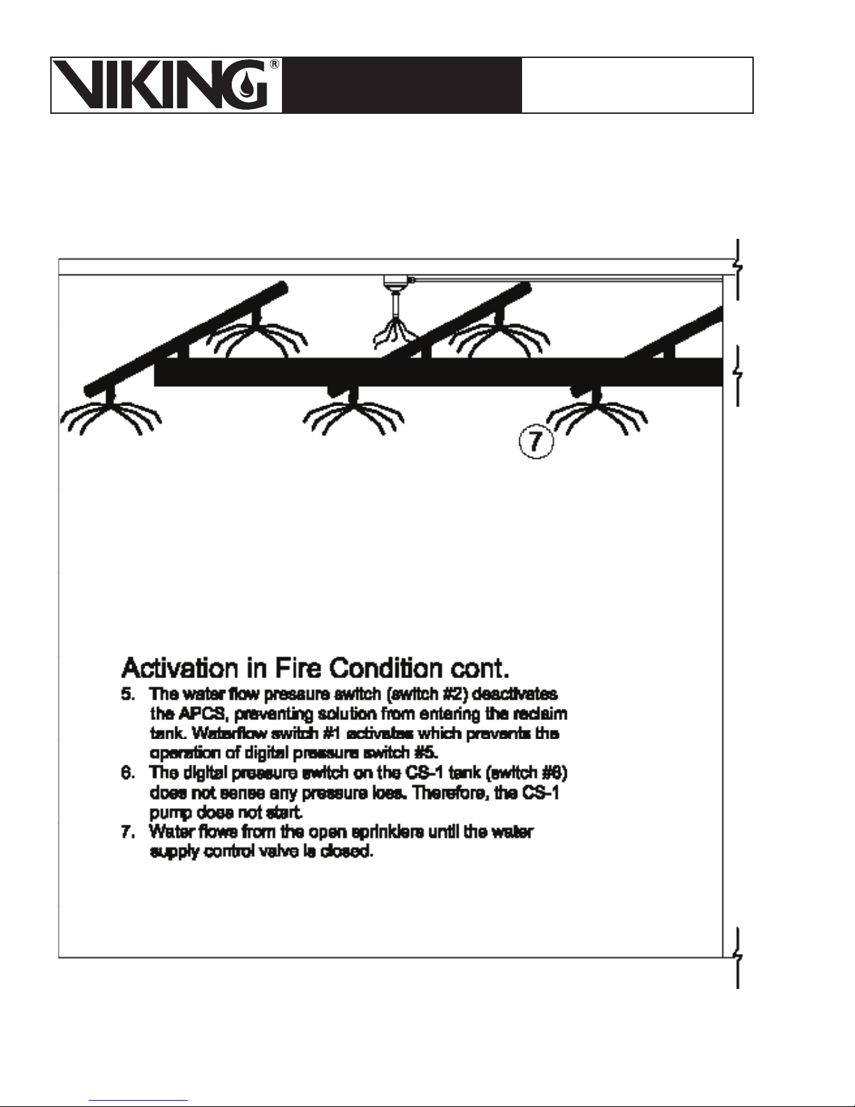
Page 98
March 7, 2008
ESFR PRE-PRIMED SINGLE
TECHNICAL DATA
INTERLOCK PREACTION
COLD STORAGE SYSTEM
The Viking Corporation, 210 N Industrial Park Road, Hastings MI 49058
Telephone: 269-945-9501 Technical Services 877-384-5464 Fax: 269-945-4495 Email: [email protected]
Page 99
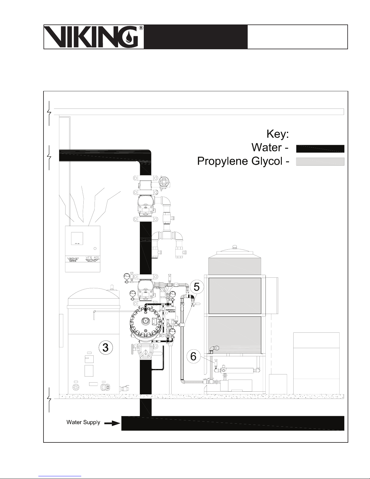
March 7, 2008
Page 99
ESFR PRE-PRIMED SINGLE
TECHNICAL DATA
INTERLOCK PREACTION
COLD STORAGE SYSTEM
The Viking Corporation, 210 N Industrial Park Road, Hastings MI 49058
Telephone: 269-945-9501 Technical Services 877-384-5464 Fax: 269-945-4495 Email: [email protected]
Page 100
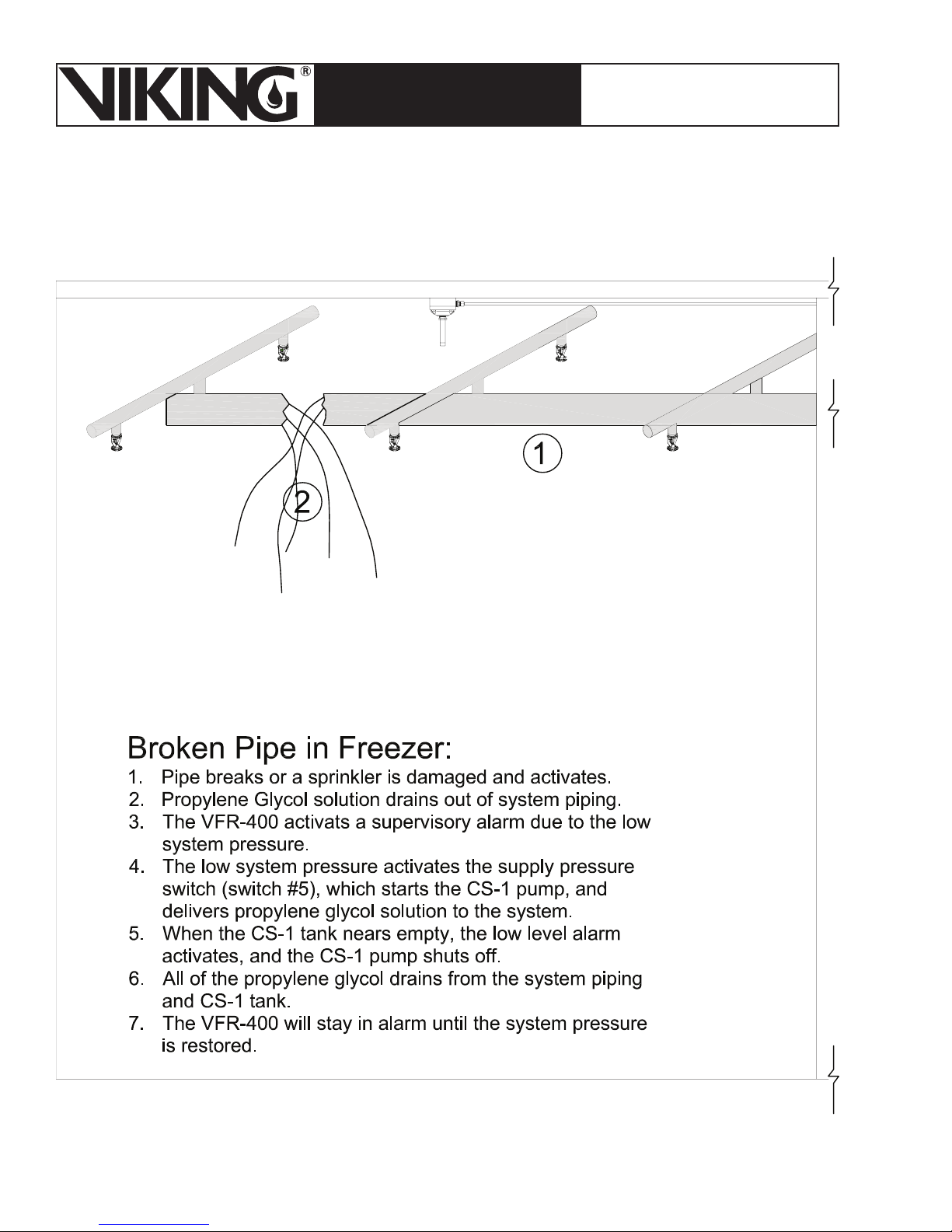
Page 100
March 7, 2008
ESFR PRE-PRIMED SINGLE
TECHNICAL DATA
INTERLOCK PREACTION
COLD STORAGE SYSTEM
The Viking Corporation, 210 N Industrial Park Road, Hastings MI 49058
Telephone: 269-945-9501 Technical Services 877-384-5464 Fax: 269-945-4495 Email: [email protected]
 Loading...