

Viking E-70-BK, E-70-BN, E-70-SS, E-70-W Product Manual
PRODUCT MANUAL
Designed, Manufactured and Supported in the USA
COMMUNICATION & SECURITY SOLUTIONS
Entry Phones with Built-In 125KHz Proximity Card Reader
Features
E-70 Series
Double Gang Entry Phone
with Built-In Proximity
Card Reader
January 11, 2017
Applications
Specifications
VIKING
• Built-in 125KHz 26-bit Wiegand proximity card reader with LED and beep
card read confirmation and EWP board protection
• Compact size: Front panel is the size of a typical single gang mid-size
wall plate
• Mounting: Flush mounts in a double gang electrical box (2.25” deep x
3.65” wide x 2.84” tall minimum) or surface mounts in a Viking model
VE-5x5 (not included, see DOD# 424) for mounting on a wall, post or
VE-GNP Gooseneck Pedestal (EWP recommended)
• Available in 4 standard faceplate finishes: Brushed Stainless Steel,
Oil Rubbed Bronze, Satin Black and Satin White
• PNL-70 faceplates: Replacement faceplates with matching screws
available in all five standard finishes
• Vandal Resistant Features: 18 gauge 304 stainless steel faceplate,
316 stainless steel push button, fiberglass reinforced plastic speaker
screen, scratch resistant powder coating, hex drive mounting screws
• Weather Resistant Features: Mylar speaker, faceplate gasket,mic
and speaker gasket, internally sealed (IP67) push button switch, self
draining mic mount and UV stable weather resistantpowder coating
(excluding E-70-SS 304 Stainless Steel faceplate)
• E-70-EWP is designed to meet IP66 Ingress Protection Rating (see
DOD# 859 for more information)
• Blue LED helps locate push button, indicate ringing and off hook
• Programmable intelligent call progress detection for automatic hang-up
on CPC, silence, busy signal, or time out
• Selectable auto answer feature for monitoring
• Programmable VOX (mic/speaker) switching speed
• VE-LIGHT: Optional faceplate light kit for use with the VE-5x5
• Door or gate communication, business delivery entrances
• Use with any of Viking’s Proximity Cards: PRX-C, PRX-C-ISO and
PRX-FOB (DOD# 198)
• Use with a Viking C-200 or C-250 to control E-70 on a single line
• Use with a Viking C-500 to control 1 or 2 (expandable to 8) E-70’s
and door/gate control on a single phone line
• Use with a Viking C-2000B to control 1 to 4 E-70’s and door/gate
control on a single phone line
• Use with a Viking ES-1 for proximity card reader door control
• Provide unique front and back door chimes and paging when
used with a Viking SLP-1, SLP-4 and C-2000B
• Residential, commercial and industrial door security
• Use with a Viking K-1900-5 or K-1900-30 for automatic speed
dialing on telephone lines or analog PABX/KSU station ports
• Use on any analog PABX station port with programmable
ringdown capability
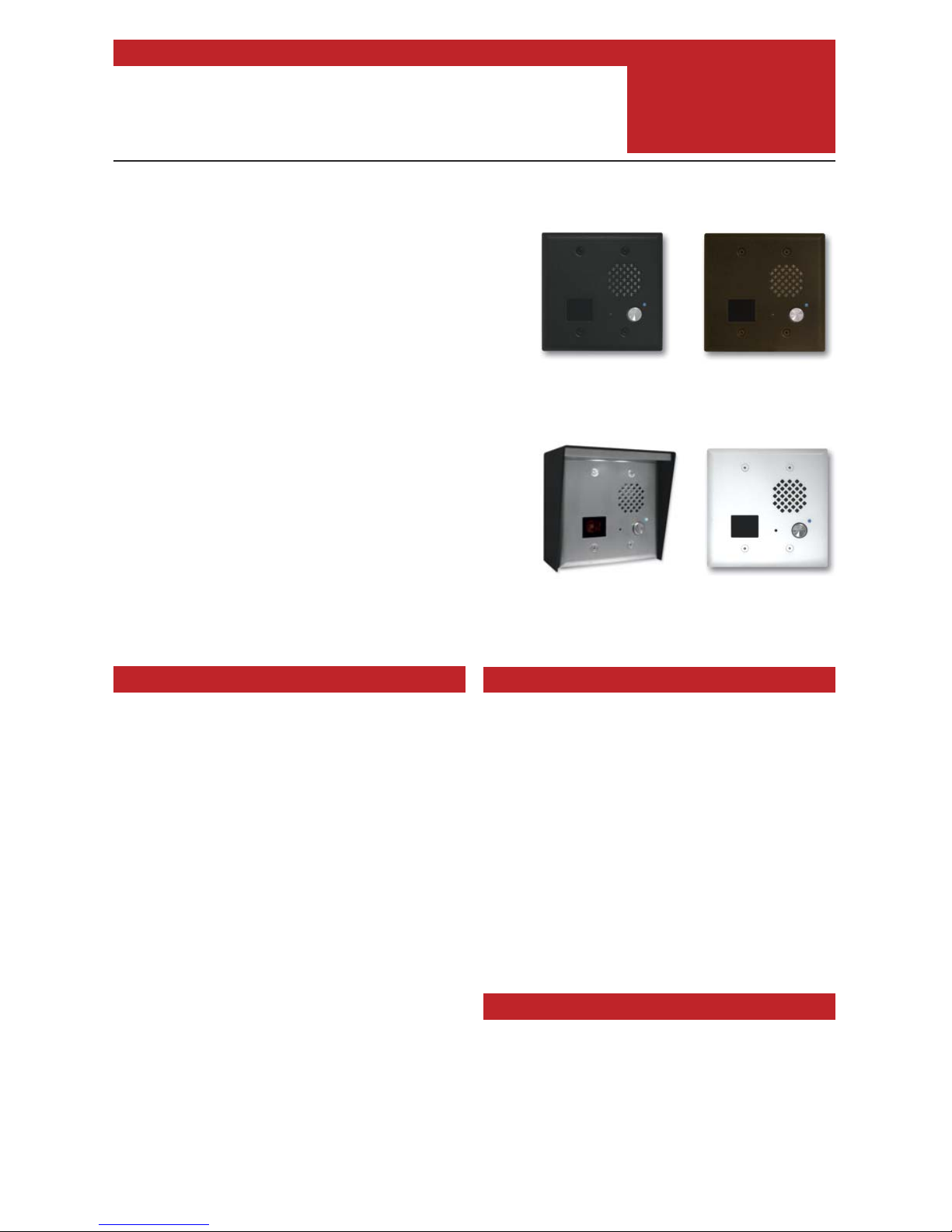
E-70-BK
“Textured Black”
(fine texture black
powder paint)
E-70-WH
“Satin White”
(satin white
powder paint)
E-70-SS
“Brushed Stainless Steel”
(similar to brushed nickel) Shown with
optional VE-5x5 surface mount box
and VE-LIGHT kit (not included)
Dimensions: Faceplate: 4.875” x 4.938” x 0.17” (123.8mm x 125.4mm
x 4.3mm), Phone: 2.84” x 1.8” x 1.65” (72mm x 46mm x 42mm)
Shipping Weight: 1.2 lbs (0.55 kg)
Operating Temperature: -30° F to 150° F (-34° C to 65° C)
Connections: (2) gel-filled butt connectors
(3M Scotchlok UR2)
(See page 2 for complete specifications)
www.vikingelectronics.com
Information: (715) 386-8861
The E-70 Series entry phones are compact, weather and vandal resistant
speaker phones designed to provide two-way handsfree audio
communication. The E-70 also includes a built-in 125KHz proximity card
reader. The card reader outputs industry standard 26-bit Wiegand data,
allowing it to be used with a Viking ES-1 door controller or any controller
compatible with 26-bit Wiegand format. The E-70's compact size allows it
to be mounted in a standard double gang electrical box. The E-70 is
available in four different attractive finishes to match your door hardware,
light fixtures, etc. Replacement E-70 faceplates (PNL70) can be
purchased separately and are available in all four standard finishes. The
E-70 entry phones can share a single phone line with house or small
business telephones when used with a Viking model C-200, C-250, C-500
or C-2000B Entry Phone controller. The E-70 entry phones can also be
connected to an unused analog station port (programmed for ring down)
on a phone system or connected directly to a telephone line when used
with a Viking model K-1900-5 or K-1900-30 auto dialer. The E-70 features
a built-in proximity card reader, microphone and speaker volume controls,
selectable auto answer for monitoring and intelligent call progress
detection for automatic hang-up when the call is completed. For outdoor
installations where the unit is exposed to precipitation or condensation,
the E-70 Series is available with Enhanced Weather Protection (EWP).
For more information on EWP, see DOD# 859.DOD# 859.
E-70-BN
“Oil Rubbed Bronze”
(satin dark brown powder paint
with fine copper metallic)
Specifications
Features Overview
Entry Phone Specifications
Power: Telephone line powered. Minimum 18V DC talk
battery voltage with a minimum loop current of 20mA. Loop
current may be boosted on low current lines with a Viking
model TBB-1B Talk Battery Booster (see DOD 632).
Dimensions: Faceplate: 123.8mm x 125.4mm x 4.3mm
(4.875” x 4.938” x 0.17”), Phone: 72mm x 46mm x 42mm
(2.84” x 1.8” x 1.65”)
Shipping Weight: 0.55 kg (1.2 lbs)
Speaker Volume: Approximately 62db maximum @ 1m
Ring Voltage: 25V AC RMS minimum (for auto answer)
CPC Disconnect Time: 300ms minimum
REN: 0.8A
Operating Temperature: -34°C to 65°C (-30°F to 150°F)
Humidity: Standard model: 5% to 95% non-condensing,
EWP model: Up to 100%
Connections: (5) gel-filled butt connectors (3M Scotchlok
UR2)
Recommended Electrical Box for Flush Mounting:
Double gang with minimum inside dimensions of 2.25” deep
x 3.65” wide x 2.84” tall (Carlon BH234R or equivalent)
Recommended Surface Mount Box: Viking model VE-5x5
(DOD# 424)
WARNING: Do NOT use a typical “wet location box” as not
all styles seal properly with the E-70 faceplate.
Proximity Card Reader Specifications
Power: 5 to 14V DC @ 60mA maximum
Maximum Cable Length: 500 ft 24 Awg stranded shielded
(Belden 9537)
Frequency: 125KHz
Format: 26 bit Wiegand
Read Range: 1.25” to 2.0”
Technologies Supported: Viking PRX-C, PRX-C-ISO,
PRX-FOB, certain legacy HID® proximity protocols* and
certain AWID 125Khz proximity protocols**
Transducer: Beeps during card read
LED: Red, turns off during card read
Humidity: Up to 100% (fully potted EWP)
Operating Temperature: -34° C to 65° C (-30° F to 150°
F)
* HID and the HID logo are registered trademarks of HID
Global Corporation, an ASSA ABLOY company. All other
trademarks are the property of their respective owners.
** AWID is a trademark of Applied Wireless Identification
Group.
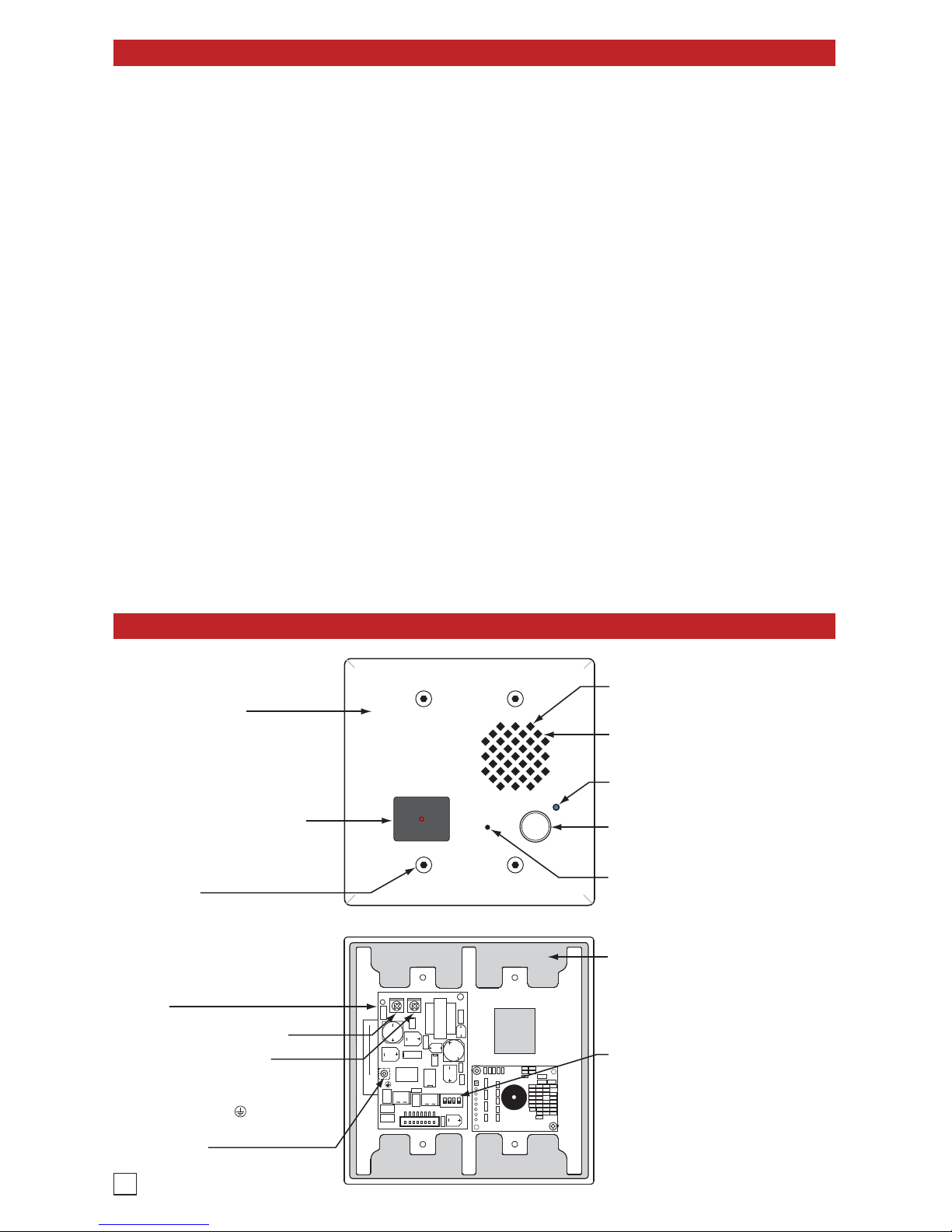
Faceplate Gasket: 1/8" thick closed cell PVC
to provide a water-tight seal.
Earth Ground: To increase surge protection,
loosen the screw labeled (as shown) and
fasten a wire with ring terminal (included) from
the mounting screw to Earth Ground (grounding
rod, water pipe, etc.)
Speaker Screen: Fiberglass Reinforced Plastic
speaker screen with 0.028" slots to prevent
punctures from paperclips, etc.
Faceplate: 18 guage 304 stainless steel
faceplate with super durable UV stable powder
paint to prevent fading and resist scratching.
Speaker: Mylar speaker with rubber gasket to
maintain water-tight seal and eliminate water
deterioration.
Microphone: Omni-directional microphone
with protective water-resistant cloth.
Mounting Screws: 6-32 x 1.25" long flathead
with 5/64" hexdrive, 18-8 stainless steel to
prevent corrosion.
VIKING
Model:
XXXXXXX
xxxxxx
S/N:
REN 0.8A:
XXXXXXXX
Viking Electronics, Inc. (715) 386-8861
1531 Industrial St., Hudson, WI 54016
P/N:
DEV:
Complies with FCC Part 15 and 68 Reg. No: US:AH3TE08A22264
VIKING
Blue LED: Helps locate the push button,
indicate ringing and off-hook conditions.
Push Button Switch: Push to initiate call,
push again to disconnect. Solid 304 stainless
steel internally sealed per IP67.
Speaker Volume
Microphone Volume
Entry Phone Board: Compact analog speaker
phone with call progress detection for automatic
disconnect.
Proximity Card Reader: 26-bit Wiegand,
125KHz, red LED turns off and transducer will
beep during card read. Fully potted EWP. Read
range 1.25" to 2.0". Impact resistant
polycarbonate lens with water-tight gasket.
DIP Switches (see page 6):
1: Auto Answer Feature (on/off)
2: Dial Tone Detection (on/off)
3: Programming Switch (normal/programming)
4: LED (on/off)
2
Installation
A. New Construction Flush Mounting
B. Old Work / Remodel Flush Mounting (Using an recommended Carlon BH234R
Rough-In Box)
C. Surface Mounting
Step 1
Recommended mounting heighy to bottom of the rough-in box is 50” - 54”. Front of box
should stick out approximately ½" from front surface of wall stud (this may vary depending
on the walls sheathing and siding thickness). Caution: Rough-In box must be mounted
LEVEL and must NOT stick out beyond the front surface of siding.
Step 2
To maintain a vapor barrier on outside wall applications, caulk around the box, filling any
gaps between the box and the rough opening. Apply caulk to any holes in the box around
wires, etc.
Step 3
When installing siding cut a hole just large enough for the Rough-In box opening.
Caution: Too large of a hole can cause plate misalignment and compromise the gasket
seal. Note: A siding mounting block is recommended when mounting to vinyl siding or
siding with a 4 inch or less horizontal lap. Contact siding installer for the correct mounting
block.
Step 1
Recommended mounting heighy to bottom of the rough-in box is 50” - 54”. Make sure
mounting location is free of wall studs, wires, etc..
Step 2
Place Rough-In box LEVEL against siding. Trace outline of box onto siding. Note: A
siding mounting block is recommended when mounting to vinyl siding or siding with a
4 inch or less horizontal lap. Contact siding installer for the correct mounting block.
Step 3
Cut a hole through the siding and wall sheathing just large enough for the rough-in box.
Caution: Too large of a hole can cause plate misalignment and compromise the gasket
seal.
Step 4
The front surface of the Rough-In box can be mounted flush against wood siding or
can be recessed and mounted flush against wall sheathing when mounting on
aluminum, steel or vinyl siding.
Step 5
When mounting to 5/8 inch thick or less wall sheathing the two attached screws with
wing brackets can be used to secure the rough-in box. When mounting to surfaces
thicker than 5/8 inch, four standard flat head dry wall screws can be used to secure the
Rough-In box through its mounting ears. (See page 4 Section D.)
Step 6
To maintain a vapor barrier on outside wall applications, caulk around the box, filling
any gaps between the box and the rough opening. Apply caulk to any holes in the box
around wires, etc.
The E-70 is designed to be flush mounted into a double gang rough-in box with minimum inside
dimensions of 2.25” deep x 3.65” wide x 2.84” tall. The E-70 can also be surface mounted in a Viking
model VE-5x5 (not included, see DOD# 424).
WARNING: Do NOT use a typical “wet location box” as not all styles seal properly with the E-70
faceplate.
A Viking model VE-5x5 can be used to surface mount an E-70 to a wall or post. ecommended
mounting heighy to bottom of the rough-in box is 50” - 54”. Drill a small wire exit hole in wall. Pull
wire through and seal hole around wire with putty or caulking. Route wire into the VE-5x5 box,
securely screw it to wall or post and seal hole in box around wire with putty or caulking. Note:
Conduit may also be used when surface mounting wire, but should not enter through the top of the
VE-5x5. When routing wiring from above, a drip loop is required. WARNING: Do NOT use a typical
“wet location box” as not all styles seal properly with the E-7 0 faceplate.
3

4
D. Mounting the Faceplate
After the Rough-In box or VE-5x5 is securely mounted, caulking between the box and rough opening
is completed (if required), and wires are connected, remove paper liner from face plate gasket back
and place it on back side of the faceplate aligning with push button hole. Push the 1-1/4" 6-32
screws through faceplate holes and small holes in gasket, the faceplate gasket should retain the
screws. Position Circuit board mounting plate over screws. Align screws with double gang box
bosses and tighten face plate until gasket is fully collapsed and the push button is protruding through
the clearance hole in the face plate. Included 1/4" thick gasket will provide an adequate seal for
most siding surfaces; however for rough surfaces (ie: brick, stucco, etc.) additional caulking may
be required.
Circuit Board
Mounting Plate
(included)
1/4" Thick Foam
Faceplate Gasket
(included)
Facplate
(included)
(4) 6-32 x 1.25" Long
5/64" Hexdrive
Flathead Screws
(included)
"Old Work" Double Gang Rough-In Box
with minimum dimensions of:
3.65"W x 2.84"H x 2.25"D
. (Carlon BH234R box shown, not included)
Optional VE-5x5 Surface Mount Box
with Black Satin Powder Paint Finish,
not included (DOD# 424)
WARNING: Do NOT use a wet location box.
Optional VE-LIGHT Kit can be used
to illuminate the E-70 faceplate,
see DOD# 428.
2.25”
5.14”
5.22”
3.25”
3.63”
3.63”
-OR-
(2) Junction Box to
Double Gang Adapter
Plates and (4) 5/64 Hex
Drive Flat Head Screws
(included with the E-70)
*2.25"
Deep
Min.
** LED
Light Pipe
(included)
(9) 3-Wire Gel-Filled
Butt Connectors
(included)
Green
Red
Wires from
Phone Board
W/BL
BL/W
Wing Brackets
Belden
9537
Cable
Wires from
Proximity
Card Reader
Black
Red
Black
Red
Green
White
Green
White
CAT5E
Cable
* CAUTION: Excessive wire length and/or using a rough-in box with inadequate depth can apply force to the
circuit board causing physical damage.
** Important: Push LED light pipe into faceplate hole, then place faceplate upside down on a clean flat surface
and push down on back side of plate until light pipe is fully seated and straight. WARNING: Inserting the light
pipe more than one time can cause a loose fit.
 Loading...