

Viking DFRD144, DFUR143, DFUR144, DFUW144, DUAR143 Service Manual
...
Service
Manual
This manual is to be used by qualied appliance technicians only.
Viking does not assume any responsibility for property damage
or personal injury for improper service procedures done by an
unqualied person.
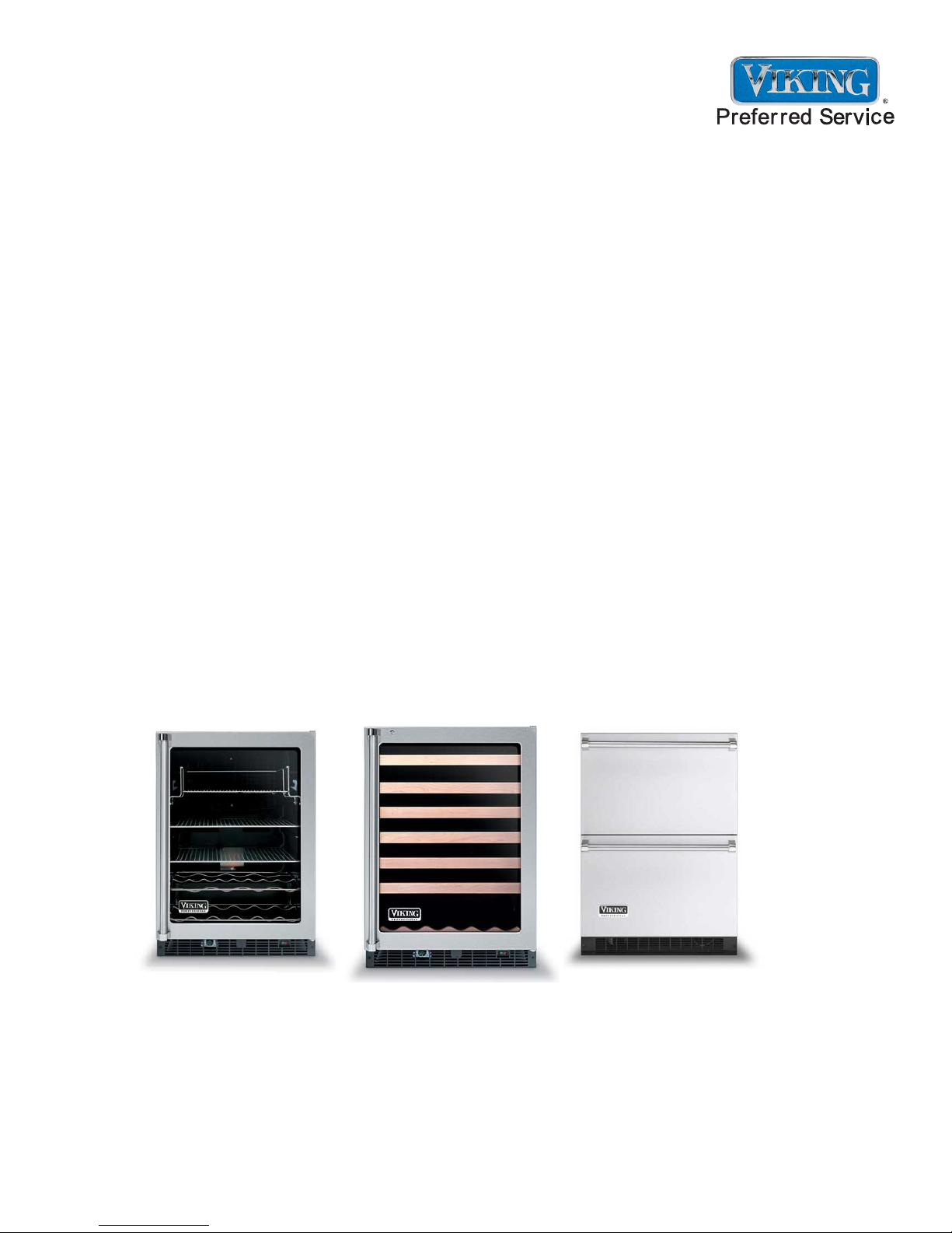
2008 24 Inch
Undercounter
Refrigeration
This Base Manual covers general and
specic information including, but not
limited to the following models:
DFRD144
DFUR143
DFUR144
DFUW144
DUAR143
DUAR144
DURD144
DUWC14 4
VUAR143
VUAR144
VURD144
VUWC144
SMR-0003
July 2008
Important Information
Important Notices for Service Technicians
Viking Range Corporation will not be responsible for personal injury or property damage arising from service
performed by anyone other than Viking Factory Authorized Service Agencies. Pride and workmanship go into every
product to provide our customers with quality products. It is possible, however, that during its lifetime a product may
require service. Products should be serviced only by a qualied service technician who is familiar with the safety
procedures required in the repair and who is equipped with the proper tools, parts, testing instruments and the
appropriate service information.
IT IS THE TECHNICIANS RESPONSIBILITY TO REVIEW ALL APPROPRIATE SERVICE INFORMATION BEFORE
BEGINNING REPAIRS.
All safety information must be followed as provided in this document
To avoid risk of electrical shock that can cause death or severe personal injury, disconnect unit from power
before servicing unless testing requires power.
IM PO RTAN T: Wires removed during disassembly must be replaced on correct terminals to ensure proper
grounding and polarization.
Contact Information:
For authorized technical assistance:
Viking Technical Service
1-800-914-4799
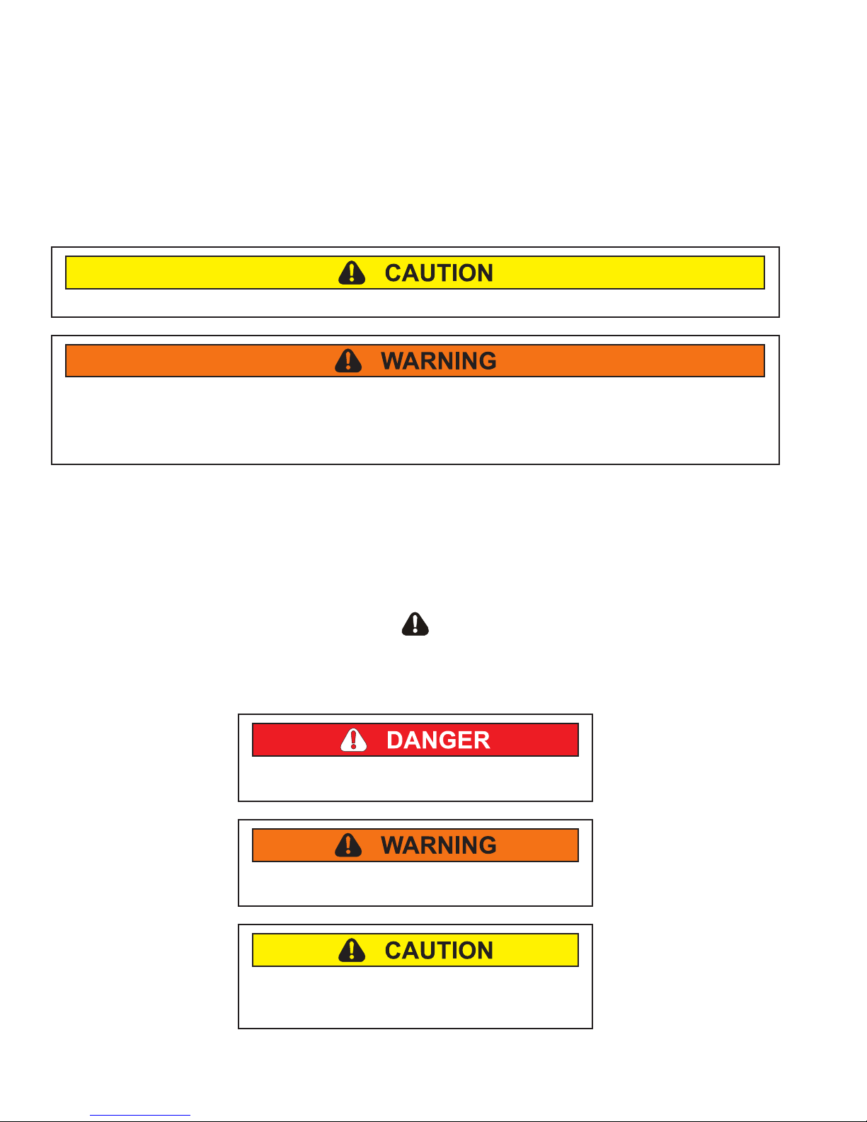
Safety Symbols
Recognize these Safety Symbols, Words, and Labels:
DANGER-Immediate hazards which WILL result in
severe personal injury or death.
WARNING-Hazards or unsafe practices which
COULD result in severe personal injury or death.
CAUTION-Hazards or unsafe practices which
COULD result in minor personal injury, product or
property damage.
2 SMR-0003 © Viking Range Corporation

Table of Contents
Important Information ..................................................... 2
Important Notices for Service Technicians ................. 2
General Information ....................................................... 4
Unit Specications ...................................................... 4
Wine Cellar, Beverage Center & Refrigerated Drawers
Unit Specications ...................................................... 4
Serial Nameplate ........................................................ 4
Before Servicing ......................................................... 4
Basic Refrigeration Tools ........................................... 5
Installation .................................................................. 5
Electrical Requirements ............................................. 5
Sealed System Basics ...............................................5
Diagnostic Information ...................................................6
Low Side leaks ........................................................... 6
High Side Leaks ......................................................... 6
Restricted Capillary Tube ........................................... 6
Access Valves ............................................................ 6
Evaporator Frost Pattern ............................................ 6
Pressure and Temperature ......................................... 6
Temperature-Pressure Chart for R-134a .................... 6
Re-charging ................................................................ 7
Condenser .................................................................. 7
Compressor ................................................................ 7
Evaporator .................................................................. 8
Thermistors ................................................................ 9
Resistance versus Temperature Chart ....................... 9
User Interface Panel and Tru Protect™ System ...... 10
Starting the Unit .......................................................10
Setting the Temperature Mode ................................. 10
Adjusting the Temperature Control ........................... 10
Interior Light and Switch ........................................... 10
Sabbath Mode .......................................................... 10
Warning Alarm .......................................................... 11
Resetting the Alarms ................................................ 11
Show Room Mode .................................................... 11
Error Code Detection ............................................... 11
Error Code Detection Reference .............................. 11
Service Diagnostics Mode ........................................ 12
Software Model Number ..........................................12
Available Component Tests ...................................... 12
Ordering Parts .......................................................... 12
Troubleshooting Procedures ........................................13
Component Testing Procedures ................................... 16
Disassembly ................................................................. 19
Mechanical Baseplate: ............................................. 19
Compressor .............................................................. 20
Condenser ................................................................ 21
Condenser Fan ........................................................21
Thermistors .............................................................. 21
Lights ........................................................................ 21
Wiring Diagrams and Schematics ................................ 23
Wine Cellar Wiring Schematic .................................. 23
Beverage Center Wiring Schematic ......................... 24
Refrigerated Drawer Wiring Schematic .................... 25
© Viking Range Corporation SMR-0003 3
General Information
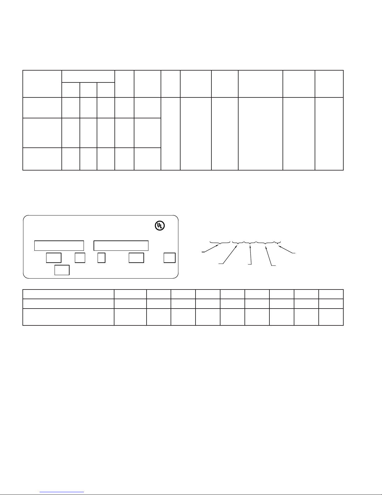
YYYYMMDDSSSA
DETAIL "B"
YEAR
MONTH
DAY
SERIAL
ASSEMBLY SITE
MODEL NO. SERIAL NO.
BTU/HR
R134A
OZ TEST PRESSURE
"J" PSI LOW SIDE
"K" PSI HIGH SIDE
905L
LISTED
HOUSEHOLD
C
"A"
AMPSPHHZVOLTS
DETAIL "B"
"C"
"D" "E" "F"
"G"
"H"
REFRIGERATOR
GREENWOOD, MISSISSIPPI 38930 USA
VIKING RANGE CORPORATION
Unit Specications
The unit specications will vary among the models listed in this service manual. See chart below for unit
specications related to the model that you are servicing.
Wine Cellar, Beverage Center & Refrigerated Drawers Unit Specications
Power
Cord
Length
(ft)
Compressor
Type
System
Refrigerant
Control
Temperature
Control
Condenser
Fan Motor
Model
DFUW144
DUWC144
VUWC144
Cabinet Dimensions (in)
Height Width Depth
34 23 ⅝ 24 ¼ 166 2.8
Weight
Refrigerant
(lbs)
Charge
(oz)
Evaporator
Fan Motor
DFUR143/144
DUAR143/144
VUAR143/144
DFRD144
DURD144
VURD144
34 23 ⅝ 24 ¼ 166 3.6
34 23 ⅞ 24 ¼ 170 3.6
7 Piston type
Capillary
tube
Electronic Control
with LED display,
thermistor input,
and Tru Protect™
2.3 W 1300
RPM
12VDC
Serial Nameplate
The serial nameplate is located inside of the unit on the upper left hand wall. The serial number will need to be given
when inquiring about the unit or ordering parts. See illustration below for a sample serial tag with manufacturing date
code logic.
A B C D E F G H J K
DFUW, DUWC, VUWC 144 Detail B 115 60 1 440 3.3 2.8 140 300
DFUR, DUAR, VUAR 143/144
DFRD, DURD, VURD 144
Detail B 115 60 1 440 3.3 3.6 140 300
Before Servicing
Always disconnect power to any Viking product •
before attempting to service it. Always verify that
power has been disconnected.
If the unit has been running, use caution around the •
condenser and copper tubing. These areas may be
very hot.
Use caution around the condenser ns and •
baseplate edges. These areas are sharp.
Refrigerant is under high pressure. Always evacuate •
any system before attempting to open it.
Reasonable care and safe work methods should •
be practiced when working on any Viking product.
Never work with energized electrical equipment in
wet or damp areas.
4 SMR-0003 © Viking Range Corporation
Use an appropriate work area and location when •
performing repairs. You will nd that it is easier to
repair undercounter units if they are set on a raised
platform or workbench.
Always wear protective safety glasses and gloves •
when working on any Viking product.
Any refrigerant, whether CFC, HCFC, or HFC (R-12, •
R-22, or R-134a), must be recovered. Federal
regulations prohibit the intentional venting or release
of refrigerants during the service repair or disposal
of an appliance.
General Information
Basic Refrigeration Tools
The following list contains some of the tools required for
basic refrigeration repairs:
Hoses with R-134a couplers (must meet standards •
for handling R-134a refrigerant)
Approved and certied recovery system for R-134a•
Manifold gauge set for R-134a•
Charging cylinder with R-134a•
Weight scale (preferably in ounces to the nearest •
tenth of an ounce)
Access valves•
Small and large tubing cutter•
Brazing torch•
Swaging tools•
Multimeter•
Leak detection equipment for detection of R-134a•
Standard hand tools (assorted Phillips and standard •
screwdrivers, sockets, Allen wrenches, adjustable
wrenches, etc.)
Rivet gun and assorted rivets•
Drill motor and assorted metal drills•
Installation
Unit can be installed freestanding or built-in. The •
front of the unit must be unobstructed for proper air
circulation and operation at all times.
Area should be ventilated and without extreme •
temperatures.
Unit must be installed away from the elements of •
nature. Do NOT use the unit outdoors unless it is
U.L. approved for outdoor use; doing so may void
any warranties.
Unit must be on a • LEVEL surface capable of
supporting the loaded weight of the unit.
Sealed System Basics
The following should always be practiced with any
sealed system that has been opened. ONLY OPEN
THE SEALED SYSTEM AS A LAST RESORT AND
AS A FINAL DIAGNOSIS. Always check other areas of
operation such as wiring, airow, thermostat, etc. before
opening up the sealed system. Many times these areas
can resemble sealed system problems. The diagnosis
of a sealed system can be determined by accurate
pressure and temperature measurements. Also,
checking the evaporator frost pattern is a great way to
tell if a charge is adequate within a system.
Use a leak detection system that will detect R-134a 1.
refrigerant. Leaks need to be found on any leaking
system BEFORE the repair takes place.
The drier must be replaced anytime the sealed 2.
system is opened. Always use a new drier. Failure
to do so may cause repeated system failure in the
future.
Limit time the system is opened. 3. DO NOT EXPOSE
THE OPEN SYSTEM FOR MORE THAN 15
MINUTES. This will result in sealed system failure.
Leave replacement parts sealed and/or pressurized
until ready to install.
The compressor must be replaced if there is a low 4.
side leak. Moisture has been drawn into the system
if the unit has been running for an extended period
of time. Be sure to ush the system with dry nitrogen
gas and evacuate to 50 microns before re-charging
(see Low Side Leaks).
A new evaporator assembly must be ordered if the 5.
capillary tube is found to be plugged or severely
restricted. Restrictions cannot be ushed out.
Be sure to purge the system with dry nitrogen gas 6.
after nal brazing. This will ush out any air or
moisture that may have entered the system before
being absorbed into the ester oil.
ELECTRICAL SHOCK HAZARD-Failure to follow
these requirements could result in personal injury,
electrical shock, or re.
Electrical Requirements
115 VAC, 60 Hz., single phase power is needed•
Use an outlet with a 15 amp delayed action fuse •
or circuit breaker. DO NOT PUT A FUSE ON THE
NEUTRAL OR GROUND OF THE CIRCUIT.
Properly grounded outlet is required for this unit.•
It is recommended that a single circuit receptacle •
be used for this unit only. DO NOT USE AN
EXTENSION CORD.
© Viking Range Corporation SMR-0003 5
Diagnostic Information
Low Side leaks
Low side leaks consist of a break in the system at the
evaporator, low side (suction) return line, or accumulator.
If a leak is found in any of these areas, moisture has
probably entered the system. The compressor and drier
will have to be replaced and the system will need to be
ushed thoroughly with nitrogen gas and evacuated to
50 microns before re-charging.
High Side Leaks
High side leaks consist of a break in the system at the
condenser, high side tubing, drier, or capillary tube. If a
leak is found in any of these areas, the system can be
ushed with nitrogen gas, evacuated to 50 microns, and
re-charged.
Restricted Capillary Tube
Moisture or other contaminants that enter the system
can cause deposits in the system. These deposits will
usually collect in the capillary tube and form a restriction
that cannot be completely removed by ushing. If the
capillary tube is found to be restricted, the evaporator,
compressor, condenser, and drier should all be replaced.
Access Valves
A temporary access valve can be used to service or
evaluate the system. From these access valves, you
can evacuate, charge, and recover the system. The
access valve can be installed on the compressor’s
process tube (this will also be a low pressure side). Be
sure to cap off access valve while servicing. This will
prevent contamination of the system and/or refrigerant
from leaking. After servicing, the access valve should
be removed. A pinch-off tool can be used to close the
system to remove the access valve and then braze the
hole for the access valve to seal the system. Be sure to
leak check after brazing.
Evaporator Frost Pattern
Checking the evaporator frost pattern is a good way
to quickly diagnose simple sealed system problems.
This can be done by allowing the unit to run (at least 10
minutes) with the door open for at least 5 minutes. This
will help speed up the normal frosting of the evaporator
plate. By visually inspecting the evaporator and feeling
it with your hands, you will see and feel frost across the
plate. It is absolutely necessary for the frost to cover the
entire evaporator plate. This will ensure the system has
been charged to its specied amount or does not have
a leak. A partial frost pattern may lead to excessive run
times or even 100% run mode. This is because the frost
does not reach the area of the evaporator thermistor, so
it does not sense the temperature required to cycle the
unit off.
6 SMR-0003 © Viking Range Corporation
Pressure and Temperature
There are two ways to measure temperature of the
evaporator plate:
Use a thermocouple to measure the temperature of 1.
evaporator plate. Thermocouple must be secured to
the evaporator when taking the measurement.
If there is proper contact between the thermistor and 2.
evaporator plate, thermistor resistance value can be
corresponded to the temperature (See Thermistors).
NOTE: Temperature and pressure readings must
be taken while unit is running. Use gauge
pressure readings from the compressor’s
process tube (low side) access valve.
Pressure will vary depending upon the ambient
temperature and current stage of operation for the unit.
For example, the unit will have pressure between 0 and
5 psi just before entering the off cycle. Normal running
pressures on the low side will average 5 to 10 lbs.
Temperature-Pressure Chart for R-134a
Degrees F Pressure (psi)
R-134a
-12 1.1 36 31.3
-8 2.8 38 33.2
-4 4.5 40 35.1
0 6.5 42 37.0
2 7.5 44 39.1
4 8.5 46 41.1
6 9.6 48 43.3
8 10.8 50 45.5
10 12.0 52 47.7
12 13.1 56 52.3
14 14.4 60 57.5
16 15.7 64 62.7
18 17.0 68 68.3
20 18.4 72 74.2
22 19.9 76 80.3
24 21.4 80 86.8
26 22.9 84 93.6
28 24.5 88 100.7
30 26.1 92 108.2
32 27.8 96 116.1
34 29.5 100 124.3
If low side pressure is below pressure in chart above,
check for the following:
A system leak1.
Capillary tube is restricted2.
Insufcient compressor (does not pump properly)3.
If low side pressure is above pressure in chart above,
check for the following:
Restricted air ow1.
Dirty condenser coil2.
Overcharged system3.
Low side leak4.
Degrees F Pressure (psi)
R-134a
Diagnostic Information
Re-charging
Re-charging of the unit should be done only after
diagnosing and repairing the system. Be sure to ush
the system with dry nitrogen gas and evacuate to 50
microns before re-charging.
The method for re-charging the unit is by weight using
vapor refrigerant. Using manifold gauge set-up, hook up
charge hoses to the access valve on the compressor’s
process tube. If any access valve is attached to the high
side process tube, remove it and then seal the tube by
brazing before charging. Charge the unit to specied
amount (see Unit Specications for charge specications
per model).
After re-charging the system, check pressures
(See Pressure and Temperature) for corresponding
temperatures and pressures. If pressures are incorrect,
check the sealed system, recover the charge, repair,
evacuate, and then re-charge.
It is normal to have some condensation or slight frost on
the suction line. Typically this will occur towards the end
of a run cycle. If the frost continues down the suction
line to the compressor, the system is overcharged. It
is important that the insulation remains on the suction
line and the capillary tube together after any repair and
that it is sealed on both ends. Be sure to replace the
refrigeration putty in the hole of the foam where the
refrigerant lines go through the back of the unit. Spread
the putty out evenly lling in the cracks to prevent air
from leaking in and out.
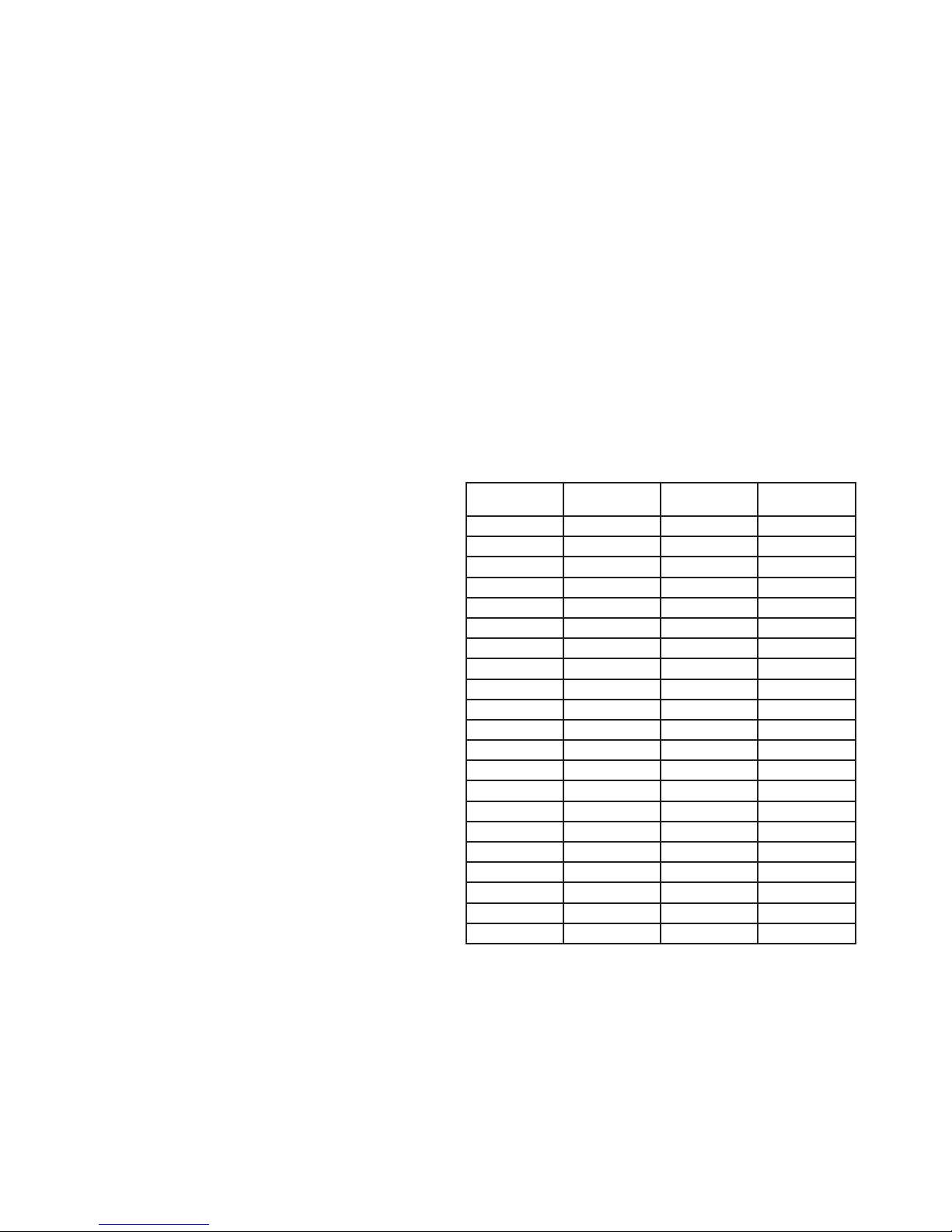
Condenser
The condenser is a steel tube serpentine with copper
alloy ns that removes heat from hot, high pressure
vapor from the compressor. The most common trouble is
lack of airow from either a restricted intake or exhaust
opening in the front of the unit. Lint, dust, hair, and
dirt build-up needs to be removed from the condenser
periodically to allow the unit to perform properly.
Compressor
The compressor is the heart of the refrigeration system.
However, it relies on other parts of the system to
function. Make certain that the other parts of the system
are functioning correctly before determining that the
compressor is faulty.
The following should be observed before concluding
the compressor is faulty:
Low high side pressures, warm evaporator plate, 1.
cool condenser coil, or little or very low current draw
from the unit will indicate a faulty compressor.
Check for continuity between the compressor 2.
terminals and the shell of the compressor. If
continuity is found, the compressor is faulty and will
need to be replaced.
Check for resistance between all compressor 3.
terminals. The resistance will vary from terminal
to terminal and from compressor to compressor
due to age and use. If no resistance is found, the
compressor is faulty and will need to be replaced.
© Viking Range Corporation SMR-0003 7
Diagnostic Information
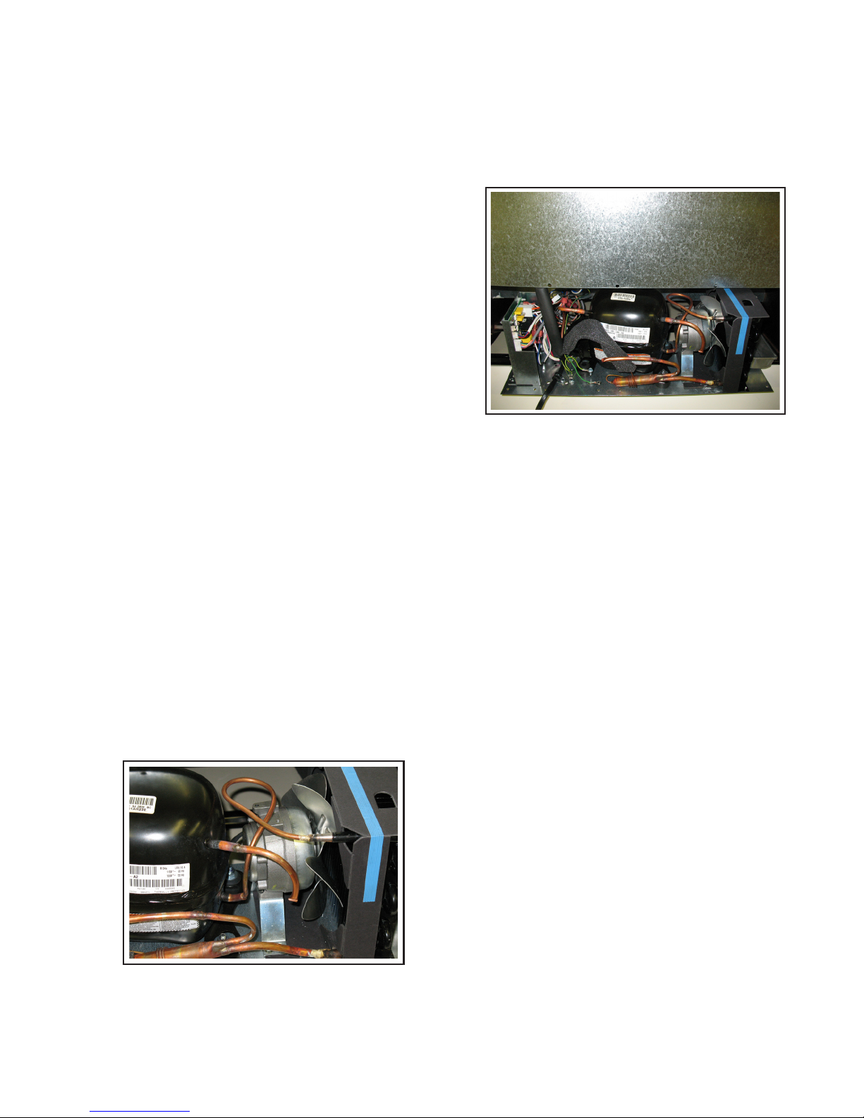
Evaporator
The evaporator uses evaporating refrigerant to remove
heat from the inside of the unit ultimately making the
interior cold. The shape and size of the evaporator may
vary among the models covered by this service manual
but the fundamentals are the same . The DFUW, DUWC,
AND VUWC use a vertical right angle evaporator plate.
The DFUR, DUAR, AND VUAR use a U-shaped plate.
The DFRD, DURD, AND VURD use a multi-purpose
evaporator plate.
It is normal for the evaporator to frost up during its run
cycle. This frost will dissipate once the unit reaches
its “cut out” temperature and the compressor and
fan stop. This condensate water will ow to the rear
of the machine in a condensate pan where it will be
evaporated from compressor and fan heat. It is very
important that the evaporator frosts in a uniform pattern
across the plate (see Evaporator Frost Pattern). A partial
frost pattern can lead to excessive run times and cooling
issues.
Evaporator plate for DFUW, DUWC, and VUWC wine
coolers
Condenser Fan
The condenser fan is used to force air over the
condenser coil. The fan will cycle on and off with the
compressor which means that when the compressor is
running so is the fan and when the compressor is not
running neither is the fan (see illustration below).
Evaporator plate for DFRD, DURD, and VURD
refrigerated drawers
Evaporator plate for DFUR, DUAR, and, VUAR
beverage centers
8 SMR-0003 © Viking Range Corporation
Make sure the motor shaft turns freely. This can 1.
be done by rotating the fan blade by hand and
observing any excessive resistance.
Check for resistance between terminals. If no 2.
resistance is found, replace the condenser fan.
Check for continuity between terminals and fan 3.
casing. If continuity is found, replace the condenser
fan.
Check current draw. Typical current draw will be 4.
0.15 amp without fan resistance. If current draw
is 0.19 amp or more, check for resistance in air
movement or objects touching the fan blade. If this
is not found, replace the condenser fan.
 Loading...