

Page 1
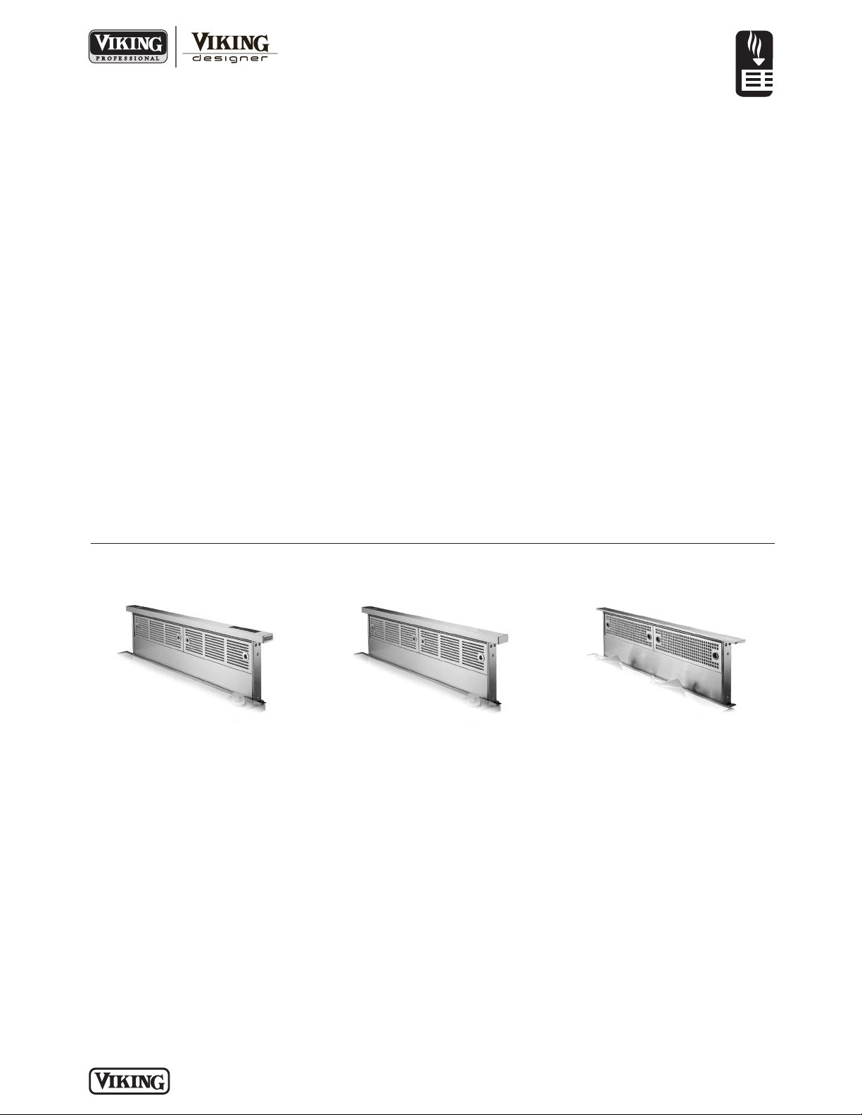
Standard Features & Accessories
VENTILATION
Built-In VersaVent™ Rear Downdraft
All models include
• Downdraft blower systems are
designed to exhaust airborne
contaminants when cooking with gas
or electric cooktops. They can be
mounted in island, peninsula, or
conventional wall locations.
• Hidden operation—mechanically raises
and lowers from countertop with the
touch of a button
• When not in use, unite retracts and
rests flush with the cooking surface
• Suitable for both island and wall
installations
• Choose from interior- or exteriorpower ventilators (see Installation
Notes & Accessories)
• Filter alert (flashing light) reminds you
to clean filters after approx. 30 hours
of use
• Four variable fan speeds ensure
efficient ventilation
• Delay/off feature allows operation for
10 minutes before automatically
shutting off
• Two removable, easy-to-clean mesh
filters are dishwasher-safe and sized
VIPR models include
• For use with Viking Professional
cooktops
• Controls on intake top
VIPR(R) models include
• For use with Viking Professional
cooktops & rangetops* (non-grill, nonwok**)
• Island rangetop must be installed with
island trim
• Remote-mounted control installs on
the countertop prevents you from
having to reach over cooking surface
or vessels
DIPR models include
• For use with Viking Designer cooktops
& rangetops (non-grill, non-wok**)
• Island rangetop must be installed with
island trim
• Remote-mounted control installs on
the countertop prevents you from
having to reach over cooking surface
or vessels
Model numbers
PROFESSIONAL DOWNDRAFT
VIPR102 – 30”W. (fits in most 30”W.
cabinets*)
VIPR162 – 36”W. (fits in most 36”W.
cabinets*)
VIPR182 – 48”W. (fits in most 48”W.
cabinets*)
PROFESSIONAL DOWNDRAFT W/REMOTE
VIPR102R – 30”W. (fits in most 30”W.
cabinets*)
VIPR162R – 36”W. (fits in most 36”W.
cabinets*)
VIPR182R – 48”W. (fits in most 48”W.
cabinets*)
DESIGNER DOWNDRAFT W/REMOTE
DIPR101R – 30”W. (fits in most 30”W.
cabinets*)
DIPR161R – 36”W. (fits in most 36”W.
cabinets*)
DIPR151R – 45”W. (fits in most 45”W.
cabinets*)
*Remote model must be used when
installed with VGRT rangetops.
**If installed behind a gas char-grill or
wok, the warranty will be voided and
performance may be below expectations.
When selecting the power and high
performance of a Viking gas char-grill or
wok, a Viking 18”H. overhead hood is
highly recommended.
Model Options
VIPR Professional
Downdraft
FINISH DETAILS FOR ALL MODELS
• Stainless Steel (SS)
VIPR Professional
Downdraft w/Remote
FINISH DETAILS FOR REMOTE MODELS
• Stainless Steel (SS)
• Black control panel and membrane
with stainless steel trim
o
4”W. x 2-1/2”D.
DIPR Designer
Downdraft w/Remote
P LA N N I N G A ND DE SI GN G U ID E
V I KI N G R A N G E . C O M • 1 - 8 8 8 - V I K I N G 1
R E V I SE D 5 / 2/ 1 1
© 2 0 1 1 V R C —INFORMATION SUBJECT TO CHANGE
Page 2
VENTILATION
2
”
(
5.
1
c
m)
A
8-1/
16”
(
20
.
5
cm)
2”
(
5.
1
c
m)
A
8-
1
1/1
6”
(
22
.
1
cm
)
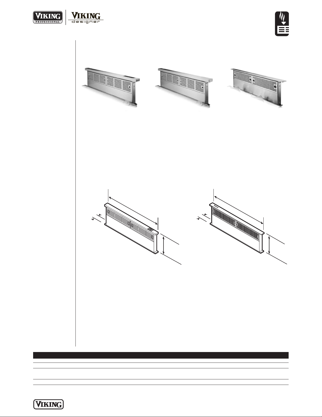
Built-In VersaVent™ Rear Downdraft
Please see
✪
Installation Notes &
Accessories for
important information,
including blower kits
and remote mounted
controls.
Dimensions & Specifications
PRODUCT DIMENSIONS
VIPR Professional
Downdraft
VIPR Professional
Downdraft w/Remote
DIPR Designer
Downdraft w/Remote
PROFESSIONAL DESIGNER
VIPR102/102R VIPR162/162R VIPR182/182R DIPR101R DIPR161R DIPR151R
Overall width (A) 30” (76.2 cm) 36” (91.4 cm) 48” (121.9 cm) 30” (76.2 cm) 36” (91.4 cm) 45” (114.3 cm)
Overall depth 2” (5.1 cm)
Overall height 29-5/16” (74.5 cm)
From countertop 8-11/16” (22.1 cm) 8-11/16” (22.1 cm) 8-11/16” (22.1 cm) 8-1/16” (20.5 cm) 8-1/16” (20.5 cm) 8-1/16” (20.5 cm)
Approx. ship. wt. 43 lbs. (19.4 kg) 50 lbs. (22.5 kg) 66 lbs. (29.7 cm) 43 lbs. (19.4 kg) 50 lbs. (22.5 kg) 66 lbs. (29.7 cm)
P LA N N I N G A ND DE SI GN G U ID E
V I K I N G R A N G E . C O M • 1 - 8 8 8 - V I K I N G 1
R E V I SE D 5 / 2/ 1 1
© 2 0 1 1 V R C —INFORMATION SUBJECT TO CHANGE
Page 3
1
2
3
4
F
I
L
T
E
R
U
P
D
O
W
N
4
”
(10
.
2
c
m)
1
/3
2
”
(
0.
08
c
m
)
to
1
/1
6
”
(
0
.1
6
c
m
)
1–3/4”
(4.4 cm)
Front to back inside
cabinet depth
Downdraft
Cooktop
Countertop
2”
(
5.1 cm)
F
I
L
T
E
R
R
E
S
E
T
1
/3
2”
(0.08
cm
)
t
o
1
/1
6”
(
0
.1
6
c
m
)
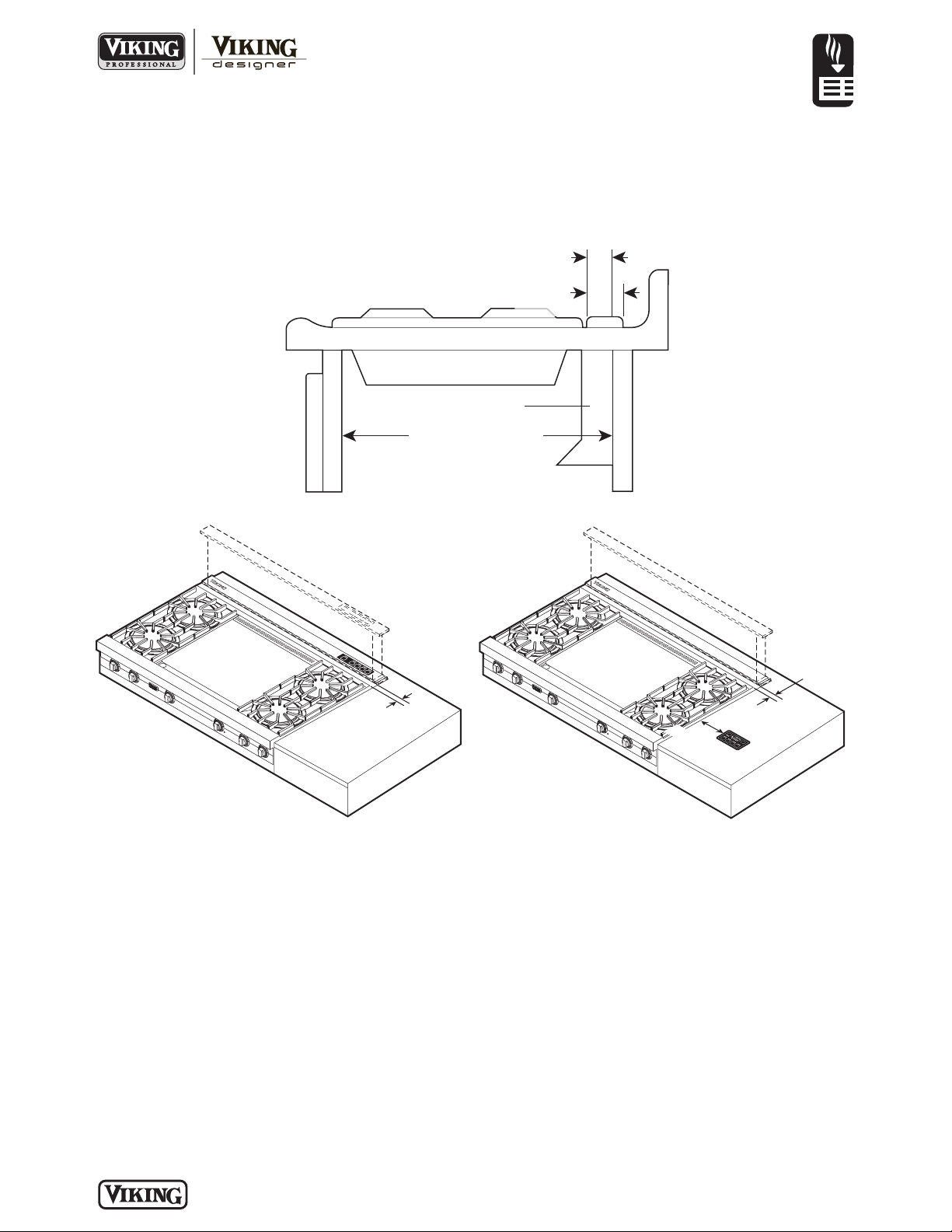
Dimensions & Specifications
CLEARANCE DIMENSIONS
VENTILATION
Built-In VersaVent™ Rear Downdraft
PROFESSIONAL PROFESSIONAL &
DESIGNER W/REMOTE
Note: Accurate alignment of cooktop and downdraft is necessary to ensure that there is no interference when air vent
is raised and lowered. There should be a gap of 1/32”–1/16” (.08 cm–0.16 cm) between the back of the cooktop and
the front of the downdraft cover. Rangetops and Designer cooktops must be used with an “R” model downdraft (with
remote control) - mounted into the countertop, at least 4” (10.2 cm) from the burners.
Countertops with a raised lip and/or
backsplash may not allow enough flat
space. Installation requires 2” of flat
countertop behind the cooking surface,
and 1-3/4” between the back edge of the
cooking surface and the inside back of
cabinet. (Viking recommends that
oversized cabinets be used for easier
installation. Also, cooktop depth can vary
greatly, causing the fit of
cooktop/rangetop and downdraft to be
tight.)
The remote mounted control (if
P LA N N I N G A ND DE SI GN G U ID E
V I K I N G R A N G E . C O M • 1 - 8 8 8 - V I K I N G 1
applicable) must be placed in the
countertop. Do not install it directly
behind or beside a burner or element.
Distance between the controls and the
edge of the cooking surface should be 4”
min.
Important—If installing in a cabinet with
same width as your downdraft model, the
outlet cannot be located on the back wall
of cabinet. In these cases, the downdraft
will cover the entire back wall of the
cabinet, so you must you must either
• mount the electrical box to a side wall or
cabinet floor—at least 12” from the back
wall, or
• mount the electrical box to a wall stud
behind the cabinet, where it will not be
covered by the downdraft, and provide a
clearance hole in the back wall of the
cabinet.
For ducting clearance, check location of
floor joists, wall studs, electrical wiring or
plumbing for possible interference.
R E V I SE D 5 / 2/ 1 1
© 2 0 1 1 V R C —INFORMATION SUBJECT TO CHANGE
Page 4

Installation Requirements
VENTILATION
Built-In VersaVent™ Rear Downdraft
VIPR Professional
Downdraft
DUCTING
• Check with a qualified and
trained installer or local codes
for makeup air requirements,
if any.
• Max. duct run length (see
Installation Notes &
Accessories)
• For best performance, use the
shortest length of ductwork
and a minimum number of
elbows.
• The system will operate most
efficiently when the ductwork
does not exceed 40’ of
equivalent duct. For longer
duct runs, increase duct size
and contact a qualified and
trained installer.
• Straight runs and gradual
turns are best; for example,
each 90° elbow is equivalent
to 5’ – 10’ (152.4 – 304.8 cm)
of straight run.
VIPR Professional
Downdraft w/Remote
UTILITY REQUIREMENTS
o
6” or 10” round elbow= 6’
of straight duct
o
3-1/4” x 10” to 6” round
transition= 2’ of straight
duct
o
3-1/4” x 10” 90° elbow= 8’
of straight duct
• Never use flexible duct; it
creates back pressure/air
turbulence and greatly
reduces performance.
GAS
• Not applicable
ELECTRICAL
• 2’-long power cord with 3pronged plug included
• Internal blowers require a
grounded outlet within reach
of the power cord
• External blowers require direct
DIPR Designer
Downdraft w/Remote
hardwiring with 2-wire with
ground, using locally-supplied
wire, and connected to the
downdraft plug (included)
• 120 VAC/60 Hz
• Max. amp usage (rating does
not include recommended
ventilator kit rating—See
Installation Notes &
Accessories)
PLUMBING
• Not applicable
Model Ventilator Kits Duct Size Max. Amps
Interior Exterior Interior Exterior Interior Exterior
VIPR102 VIDV500 VEDV900 3–1/4” x 10” (8.3 x 25.4 cm) 10” (25.4 cm) 4.0 5.7
VIPR162 VIDV500 VEDV900 3–1/4” x 10” (8.3 x 25.4 cm) 10” (25.4 cm) 4.0 5.7
VIPR182 VIDV500 VEDV900/1200 3–1/4” x 10” (8.3 x 25.4 cm) 10” (25.4 cm) 4.0 5.7/3.0
VIPR102R VIDV500 VEDV900 3–1/4” x 10” (8.3 x 25.4 cm) 10” (25.4 cm) 4.0 5.7
VIPR162R VIDV500 VEDV900 3–1/4” x 10” (8.3 x 25.4 cm) 10” (25.4 cm) 4.0 5.7
VIPR182R VIDV500 VEDV900/1200 3–1/4” x 10” (8.3 x 25.4 cm) 10” (25.4 cm) 4.0 5.7/3.0
DIPR101R VIDV500 VEDV900 3–1/4” x 10” (8.3 x 25.4 cm) 10” (25.4 cm) 4.0 5.7
DIPR161R VIDV500 VEDV900 3–1/4” x 10” (8.3 x 25.4 cm) 10” (25.4 cm) 4.0 5.7
DIPR151R VIDV500 VEDV900 3–1/4” x 10” (8.3 x 25.4 cm) 10” (25.4 cm) 4.0 5.7
Note: Proper installation/ ducting is extremely important to ensure maximum performance. Use a qualified and trained installer.
P LA N N I N G A ND DE SI GN G U ID E
V I K I N G R A N G E . C O M • 1 - 8 8 8 - V I K I N G 1
© 2 0 1 1 V R C —INFORMATION SUBJECT TO CHANGE
R E V I SE D 5 / 2/ 1 1
Page 5

7/8”
(2.2 cm)
7/8”
(2.2 cm)
2-1/4”
(5.7 cm)
20-1/4”
(51.4 cm)
27”
(68.6 cm)
1-1/2”
(3.8 cm)
1-1/2”
(3.8 cm)
27”
(68.6 cm)
28-3/4”
(73.0 cm)
D
owndraft: VIPR101/101R
Cooktop: VECU106
7/8”
(2.2 cm)
7/8”
(2.2 cm)
2-1/4”
(5.7 cm)
20-1/4”
(51.4 cm)
33”
(83.8 cm)
34-3/4”
(88.3 cm)
Downdraft: VIPR161/161R
Cooktop: VECU166
1-1/2”
(3.8 cm)
1-1/2”
(3.8 cm)
2-3/4”
(7.0 cm)
24”
(61.0 cm)
45”
(114.3 cm)
48”
(121.9 cm)
Downdraft: VIPR181R
Rangetop: VGRT548
1-1/4”
(3.2 cm)
3”
(7.6 cm)
18-3/4”
(47.6 cm)
33”
(83.8 cm)
34-1/4”
(87.0 cm)
Downdraft: VIPR161/161R
Cooktop: VGSU163
2-3/4”
(7.0 cm)
24”
(61.0 cm)
36”
(91.4 cm)
Downdraft: VIPR161R
Rangetop: VGRT536
1-5/16”
(3.3 cm)
3”
(7.6 cm)
18-3/4”
(
47.6 cm)
27”
(68.6 cm)
28-1/16”
(73.1 cm)
Downdraft: VIPR101/101R
C
ooktop: VGSU103
2-3/4”
(7.0 cm)
24”
(61.0 cm)
30”
(76.2 cm)
Downdraft: VIPR101R
Rangetop: VGRT530
1-1/2”
(3.8 cm)
1-1/2”
(3.8 cm)
33”
(83.8 cm)
TOP EDGE
CUT OUT ON DOTTED LINE
1/4” (0.6 cm)
DIA. HOLE
1/4” (0.6 cm)
DIA. HOLE
5/8” (1.6 cm)
DIA. HOLE
Built-In VersaVent™ Rear Downdraft
Installation Requirements
PROFESSIONAL ACCESS REQUIREMENTS & SITE PREPARATION
VIPR102/102R
VENTILATION
VIPR162/162R
VIPR181/VIPR181R
Model Downdraft Cutout Cooktop Cutout
VIPR102/102R
w/VECU106 27” (68.6 cm) 2-1/4” (5.7 cm) 28-3/4” (73.0 cm) 20-1/4” (51.4 cm)
w/VGSU103 27” (68.6 cm) 3” (7.6 cm) 28-1/16” (73.1 cm) 18-3/4” (47.6 cm)
w/VGRT530* 27” (68.6 cm) 2-3/4” (7.0 cm) 30” (76.2 cm) 24” (61.0 cm)
VIPR162/162R
w/VECU166 33” (83.8 cm) 2-1/4” (5.7 cm) 34-3/4” (88.3 cm) 20-1/4” (51.4 cm)
w/VGSU163 33” (83.8 cm) 3” (7.6 cm) 34-1/4” (87.0 cm) 18-3/4” (47.6 cm)
w/VGRT536* 33” (83.8 cm) 2-3/4” (7.0 cm) 36” (91.4 cm) 24” (61.0 cm)
VIPR182/VIPR182R
w/VGRT548* 45” (114.3) 2-3/4” (7.0 cm) 48” (121.9 cm) 24” (61.0 cm)
*Must use island trim. Rear countertop trim (supplied with island trim) will be used in this installation.
Width Depth Width Depth
P LA N N I N G A ND DE SI GN G U ID E
V I K I N G R A N G E . C O M • 1 - 8 8 8 - V I K I N G 1
REMOTE CONTROL CUTOUT
© 2 0 1 1 V R C —INFORMATION SUBJECT TO CHANGE
R E V I SE D 5 / 2/ 1 1
Page 6

Built-In VersaVent™ Rear Downdraft
Downdraft: DIPR100R
Cooktops: DECU105,
DGCU105, or DGSU100
Downdraft: DIPR160R
Cooktops: DECU165, DGCU165,
or DGSU160
Downdraft: DIPR150R
Cooktops: DECU155 or DGCU155
1-1/16”
(2.7 cm)
1-1/16”
(
2.7 cm)
2-1/4”
(5.7 cm)
20-5/8”
(52.4 cm)
20-5/8”
(52.4 cm)
20-5/8”
(52.4 cm)
42-7/8”
(108.9 cm)
34-7/8”
(88.6 cm)
7/16”
(1.1 cm)
7/16”
(1.1 cm)
2-1/4”
(5.7 cm)
42”
(106.7 cm)
29-1/8”
(73.9 cm)
15/16”
(2.4 cm)
15/16”
(2.4 cm)
2-1/4”
(5.7 cm)
33”
(83.8 cm)
27”
(68.6 cm)
TOP EDGE
CUT OUT ON DOTTED LINE
1
/4” (0.6 cm)
DIA. HOLE
1
/4” (0.6 cm)
DIA. HOLE
5
/8” (1.6 cm)
DIA. HOLE
Installation Requirements
DESIGNER ACCESS REQUIREMENTS & SITE PREPARATION
VENTILATION
Model Downdraft Cutout Cooktop Cutout
DIPR101R
w/DECU105 27” (68.6 cm) 2-1/4” (5.7 cm) 29-1/8” (73.9 cm) 20-5/8” (52.4 cm
w/DGCU105 27” (68.6 cm) 2-1/4” (5.7 cm) 29-1/8” (73.9 cm) 20-5/8” (52.4 cm)
w/DGSU100 27” (68.6 cm) 2-1/4” (5.7 cm) 29-1/8” (73.9 cm) 20-5/8” (52.4 cm)
DIPR161R
w/DECU165 33” (83.8 cm) 2-1/4” (5.7 cm) 34-7/8” (88.6 cm) 20-5/8” (52.4 cm)
w/DGCU165 33” (83.8 cm) 2-1/4” (5.7 cm) 34-7/8” (88.6 cm) 20-5/8” (52.4 cm)
w/DGSU160 33” (83.8 cm) 2-1/4” (5.7 cm) 34-7/8” (88.6 cm) 20-5/8” (52.4 cm)
DIPR151R
w/DECU155 42” (106.7 cm) 2-1/4” (5.7 cm) 42-7/8” (108.9 cm) 20-5/8” (52.4 cm)
w/DGCU155 42” (106.7 cm) 2-1/4” (5.7 cm) 42-7/8” (108.9 cm) 20-5/8” (52.4 cm)
DIPR101R DIPR161R
DIPR151R REMOTE CONTROL CUTOUT
Width Depth Width Depth
P LA N N I N G A ND DE SI GN G U ID E
V I K I N G R A N G E . C O M • 1 - 8 8 8 - V I K I N G 1
© 2 0 1 1 V R C —INFORMATION SUBJECT TO CHANGE
R E V I SE D 5 / 2/ 1 1
Page 7

VENTILATION
Built-In VersaVent™ Rear Downdraft
Installation Notes & Accessories
✪
Interior-Power Blower Kit
• Stainless Steel (SS)
• Mounts on any size plenum
3-1/4” x 10” duct takeoff
•
• Can transition to 6” round
• Can run duct to left, right, or down
• Max. duct run—40’ (12.2 m)
• Kit includes motor, downdraft plug, and 3-1/4” x 10” collar (for installers who prefer to rivet the ductwork to the
unit.)
Note: Exhaust capacity based on tests with 0.1 static pressure. Without applying static pressure (some brands do not),
CFM could be greatly overstated
Model Description Max. amp usage Approx. ship wt. lbs. (kg)
IDV500 500* CFM downdraft blower 4.0 32 (14.4)
V
Exterior-Power Blower Kit
• Stainless Steel (SS)
• Mounts on wall or roof (no roof cap required)
• Comes with 10” round duct takeoff plate, which mounts on any size plenum
• Max. duct run—50’ (15.2 m)
• Kit includes motor, downdraft plug, and 3-1/4” x 10” collar (for installers who prefer to rivet the ductwork to the
unit.)
• VEDV1200 must be used with VIPR181/181R
Note: Exhaust capacity based on tests with 0.1 static pressure. Without applying static pressure (some brands do not),
CFM could be greatly overstated
Model Description Max. amp usage Approx. ship wt. lbs. (kg)
VEDV900 900 CFM downdraft blower 5.7 42 (18.9)
VEDV1200 1200 CFM downdraft blower 3.0 44 (19.8)
Remote Mounted Control
• Replaces standard Designer control
• Gray control panel and membrane with stainless steel trim—coordinates with white Designer cooktops
• Easy to install
• Must be mounted into the countertop, 4” min. from burners
• 4”W. x 2-1/2”D.
Model Description Approx. ship wt. lbs. (kg)
DSRCGY Designer remote mounted control (SS/gray) 1.5 (0.7)
Compliance Information
WARRANTY SUMMARY*
• Three-year full warranty—complete product (Professional Series)
• One-year full warranty—complete product (Designer Series)
• Five-year limited warranty—all ventilator motors (Professional and Designer)
• Ninety-day limited warranty—cosmetic parts such as glass, painted, and decorative items (Professional and Designer)
*Must use Viking ventilator kits with Viking downdrafts; use of non-Viking kits voids product warranty. For complete warranty see Use & Care Guide.
Warranty valid on Viking products shipped within the United States and Canada.
P LA N N I N G A ND DE SI GN G U ID E
V I K I N G R A N G E . C O M • 1 - 8 8 8 - V I K I N G 1
© 2 0 1 1 V R C —INFORMATION SUBJECT TO CHANGE
R E V I SE D 5 / 2/ 1 1
 Loading...