

Viking DGVU Installation Manual
Viking Installation Guide
Viking Range Corporation
111 Front Street
Greenwood, Mississippi 38930 USA
(662) 455-1200
For product information,
call 1-888-VIKING1 (845-4641)
or visit the Viking Web site at
vikingrange.com
F20680B EN
09VK3130 ed.11-10
Designer DGVU Built-In Gas Cooktops
(020111)
DANGER
WARNING
CAUTION
Table of Contents
DANGER
Warnings & Important Safety Instructions _______________________________________________3
Dimensions (30”) ____________________________________________________________________6
Dimensions (36”) ____________________________________________________________________7
Specifications _______________________________________________________________________8
Cutout Dimensions __________________________________________________________________9
Downdraft Dimensions ______________________________________________________________9
Clearance Dimensions (Proximity to Cabinets)__________________________________________10
Clearance Dimensions (Wood/Composite or Steel Overlay) ______________________________11
Electrical & Gas Requirements _______________________________________________________12
General Information ________________________________________________________________16
Installation_________________________________________________________________________17
LP Conversion __________________________________________________________________18
LP Pressure Regulator Conversion_________________________________________________19
Natural Gas Conversion _________________________________________________________20
Natural Gas Regulator Conversion ________________________________________________21
Gas & Electrical Connection ______________________________________________________22
Bracket Installation ______________________________________________________________22
Final Installation ________________________________________________________________22
Final Preparation ___________________________________________________________________24
Performance Checklist ______________________________________________________________24
Service & Registration _______________________________________________________________25
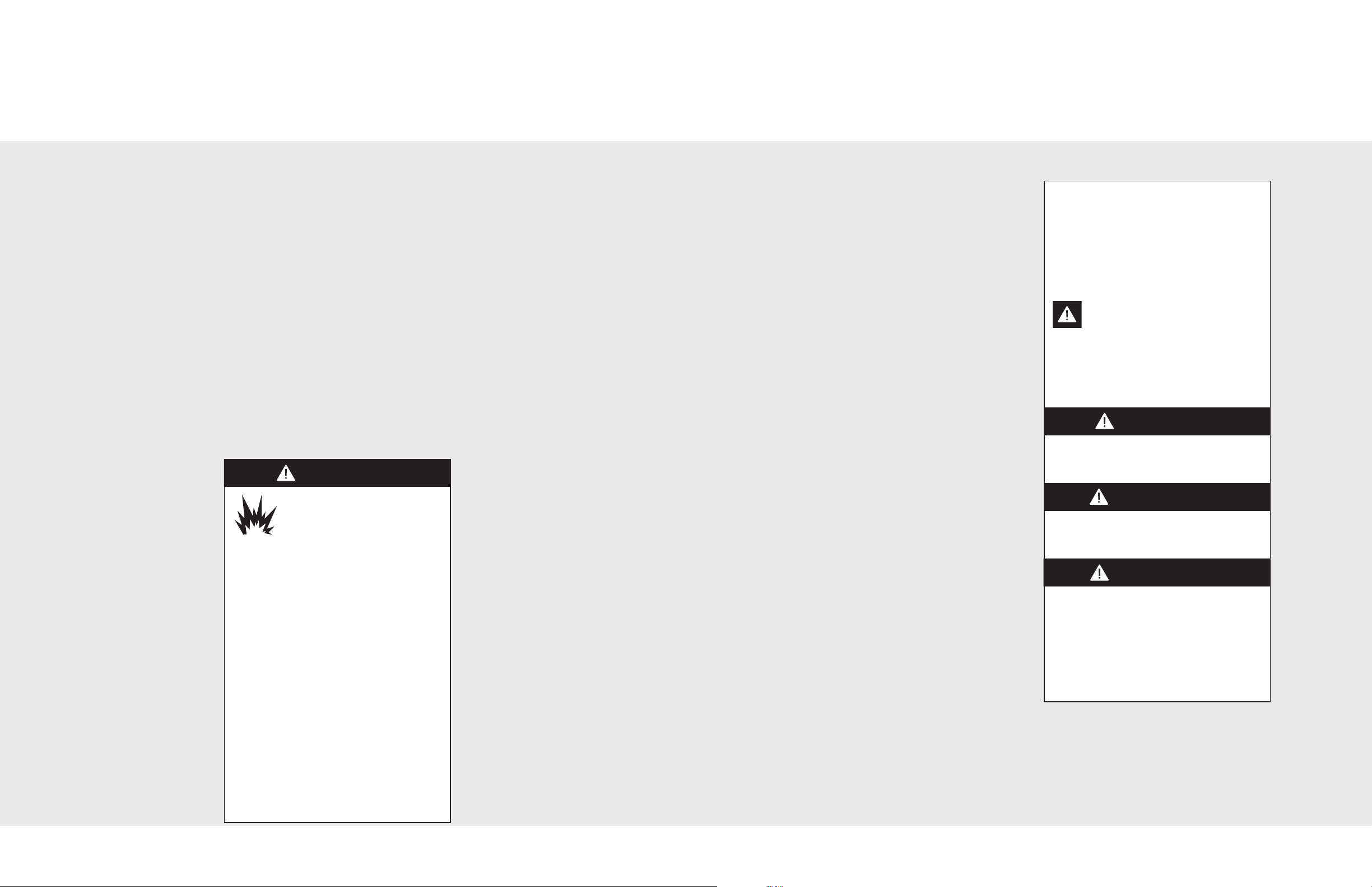
FIRE/EXPLOSION
HAZARD
IF THE INFORMATION IN
THIS MANUAL IS NOT
FOLLOWED EXACTLY, A FIRE OR
EXPLOSION MAY RESULT CAUSING
PROPERTY DAMAGE, PERSONAL
INJURY, OR DEATH.
• DO NOT store or use gasoline or other
flammable vapors and liquids in the
vicinity of this or any other appliance.
• WHAT TO DO IF YOU SMELL GAS:
–DO NOT try to light any appliance.
–DO NOT touch any electrical switch.
–DO NOT use any phone in your
building.
–Immediately call your gas supplier
from a neighbor’s phone.
–Follow the gas supplier’s instructions.
–If you cannot reach your gas supplier,
call the fire department.
• Installation and service must be
performed by a qualified installer,
service agency, or the gas supplier.
IMPORTANT
• Before beginning, read these instructions
thoroughly and carefully.
• Installation and service must be
performed by a qualified installer, service
agency, or the gas supplier.
• DO NOT remove permanently affixed
labels, warnings, or plates from the
product as this may void the warranty.
• Observe all local and national codes,
requirements and ordinances.
• Installation must conform with local codes
or in the absence of codes, the National
Fuel Gas Code, ANSI Z223.1- latest
edition and the National Electrical Code,
ANSI/NFPA 70- latest edition.
In Canada: Installation must be in
accordance with the current CAN/CGA
B149.1 & 2 Gas Installation codes and with
the current CSA C22.1 Canadian Electrical
Codes Part 1 and/or local codes.
• Installation of any gas-fired equipment
should be made by a licensed plumber.
• A manual gas shut-off valve must be
installed in the gas supply line ahead of
the cooktop in the gas stream for safety
and ease of service.
In Massachusetts: This appliance must be
installed by a licensed plumber or gas-fitter.
A “T” handle manual gas valve must be
installed in the gas supply line to the
appliance.
• Installers should leave these instructions
with the consumer who should retain them
for the local inspector’s use and for future
reference.
– Please Read and Follow
Your safety and the safety of others is
very important.
We have provided many important safety
messages in this manual and on your
appliance. ALWAYS read and obey all
safety messages.
This is the safety alert symbol. This
symbol alerts you to hazards that
can kill or hurt you and others.
All safety messages will be preceded by
the safety alert symbol and the word
“DANGER,” “WARNING” or “CAUTION.”
These words mean:
Hazards or unsafe practices
which WILL result in severe personal
injury or death
Hazards or unsafe practices
which COULD result in severe personal
injury or death
Hazards or unsafe practices which
COULD result in minor personal injury
or property damage.
All safety messages will identify the
hazard, tell you how to reduce the chance
of injury, and tell you what can happen if
the instructions are not followed.
2
3
IMPORTANT5– Please Read and FollowIMPORTANT4– Please Read and Follow
WARNING
WARNING
CAUTION
CAUTION
WARNING
WARNING
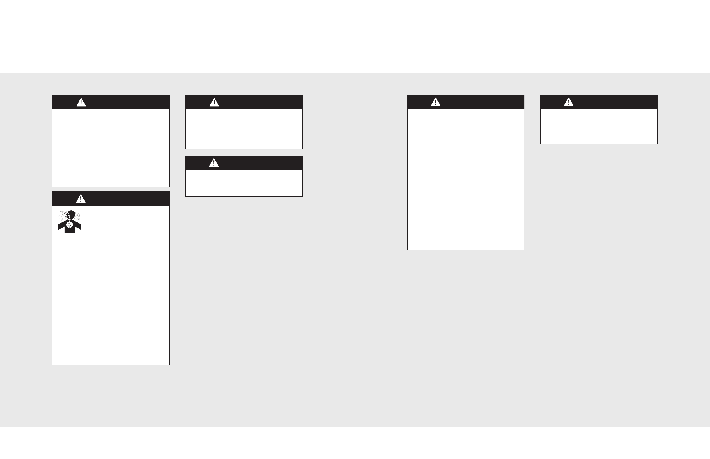
BURN HAZARD
The use of cabinets for storage above the
appliance may result in a potential burn
hazard. Combustible items may ignite,
metallic items may become hot and
cause burns. If a cabinet storage is to be
provided the risk can be reduced by
installing a range hood that projects
horizontally a minimum of 5” (12.7 cm)
beyond the bottom of the cabinets.
CHEMICAL HAZARD
If not installed, operated and
maintained in accordance
with the manufacturer’s
instructions, this product could expose
you to substances in fuel or from fuel
combustion which can cause death or
serious illness and which are known to
cause cancer, birth defects, or other
reproductive harm.
Before placing the cooktop into operation,
always check for gas leaks with a soapy
water solution or other acceptable method.
DO NOT USE AN OPEN FLAME TO
CHECK FOR LEAKS.
This appliance shall not be used for
space heating. This information is based
on safety considerations.
ELECTRICAL GROUNDING
INSTRUCTIONS
The cooktop must be electrically grounded
in accordance with local codes or, in the
absence of codes, with the ANSI/NFPA
No. 70-latest edition. Installation should
be made by a licensed electrician. This
appliance is equipped with a three-prong
grounding plug for your protection against
shock hazard and should be plugged
directly into a properly grounded
receptacle. DO NOT cut or remove the
grounding prong from the plug.
For personal safety, this appliance
must be properly grounded. DO NOT
under any circumstances cut or
remove the third (ground) prong from
the power plug.
SITE PREPARATION
It is recommended that a thorough site
inspection be conducted PRIOR to
unpacking and moving this appliance.
For example, benzene is a chemical
which is part of the gas supplied to the
cooking product. It is consumed in the
flame during combustion. However
exposure to a small amount of benzene
is possible if a gas leak occurs.
Formaldehyde and soot are byproducts
of incomplete combustion. Properly
adjusted burners with a bluish rather
than yellow flame will minimize
incomplete combustion.
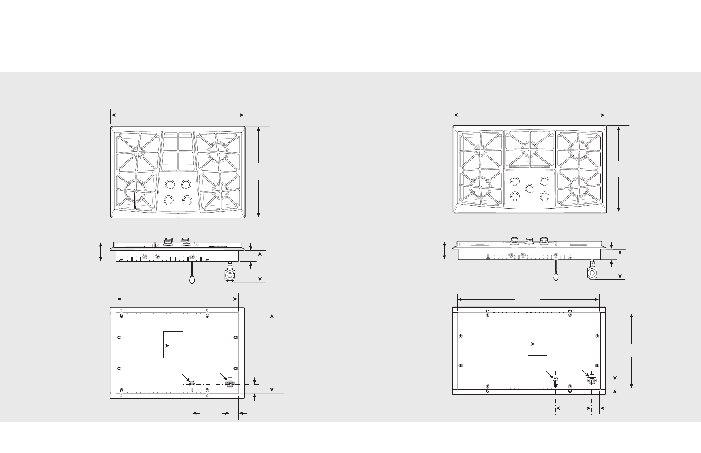
36-3/4”
(93.3 cm)
21”
(53.4 cm)
34-1/8”
(86.6 cm)
18-1/4”
(47.0 cm)
10-3/16”
(27.1 cm)
2”
(5.1 cm)
2”
(5.1 cm)
4”
(10.2 cm)
2-13/16”
(7.1 cm)
Wiring diagram
and rating
plate location
Power
cord
Regulator
7-3/16”
(18.3 cm)
Dimensions
30-3/4”
(
78.2 cm)
21”
(53.4 cm)
28-1/8”
(71.4 cm)
18-1/4”
(47.0 cm)
10-3/16”
(27.1 cm)
2”
(5.1 cm)
2”
(5.1 cm)
4”
(10.2 cm)
2-13/16”
(7.1 cm)
Wiring diagram
and rating
plate location
Power
cord
Regulator
7-3/16”
(18.4 cm)
Dimensions
30” Gas Cooktop
36” Gas Cooktop
6
7

C
B
A
Specifications
C
EF
D
A
B
Designer Gas Cooktops
Cutout Dimensions
GVU200
Description
Overall width
Overall height from bottom
to top of grate
Overall depth from rear
Cutout width
Cutout height
Cutout depth
Gas requirements Accepts standard residential ½” (1.3 cm) I. D. gas service line.
Electrical requirements
Maximum amp usage 2.0 amps
Surface element rating
Left front
Left rear
Center front/rear
Right front
Right rear
Approximate
shipping weight
Shipped natural; gas regulator and orifice spuds are supplied with the product.
To field convert from natural or LP/Propane, the orifice spuds and regulator
D
30-3/4” (78.1 cm) 36-3/4” (93.3 cm)
4” (10.2 cm)
21” (53.3 cm)
28-1/2” (72.4 cm) min. to
29” (73.6 cm) max.
2-13/16” (7.1 cm)
19” (48.3 cm) min. to
19-5/8” (49.8 cm)
must be physically changed.
120 VAC/60 Hz; 4 ft. (121.9 cm), 3-wire cord with grounded
3-prong plug attached to product.
15,000 Nat./LP (BTU)
(4.4 Nat./LP (kw))
4,000 Nat./LP (BTU)
(1.0 Nat./LP (kw))
N/A
9,000 Nat./LP (BTU)
(2.6 Nat./LP (kw))
12,000 Nat./LP (BTU)
(3.5 Nat./LP (kw))
35 lb. (15.9 kg) 60 lb. (27.2 kg)
GVU260
D
34-1/2” (87.6 cm) min. to
35” (88.9 cm) max.
15,000 Nat./LP (BTU)
(4.4 Nat./LP (kw))
4,000 Nat./LP (BTU)
(1.0 Nat./LP (kw))
9,000 Nat./LP (BTU)
(2.6 Nat./LP (kw))
12,000 Nat./LP (BTU)
(3.5 Nat./LP (kw))
12,000 Nat./LP (BTU)
(3.5 Nat./LP (kw))
DGVU200 DGVU260
A 28-1/2” (72.4 cm) min. to
29” (73.6 cm) max.
B 19” (48.3 cm) min. to
19-5/8” (49.8 cm)
C 1-1/2” (3.8 cm)
34-1/2” (87.6 cm) min. to
35” (88.9 cm) max.
Note: Based on 24” deep cabinet with 3/4” backsplash.
Downdraft Dimensions
DGVU200 DGVU260
A 29-1/8” (74.0 cm) 34-7/8” (88.6 cm)
B 20-5/8” (52.3 cm)
C 27 (68.6 cm) 33” (84.0 cm)
D 2-1/4” (5.7 cm)
E 1-1/16” (1.1 cm) 15/16” (1.0 cm)
F 1-1/16” (1.1 cm) 15/16” (1.0 cm)
8
Note: Refer to the downdraft installation instructions.
9
 Loading...