

Page 1

Viking Installation Guide
Freestanding Gas Ranges
Page 2
IMPORTANT:
PLEASE READ AND FOLLOW
• Before beginning, please read these instructions
completely and carefully.
• Do not remove permanently affixed labels, warnings, or
plates from the product. This may void the warranty.
• Please observe all local and national codes and
ordinances.
• Please ensure that this product is properly grounded.
• The installer should leave these instructions with the
consumer who should retain for local inspector’s use and
for future reference.
Installation must conform with local codes or, in the
absence of codes, the National Fuel Gas Code, ANSI
N CANADA:
Z223/NFPA 54 or the latest edition.
Installation must be in accordance with the current CSA
B149.1 & 2 Gas Installation codes and/or local codes.
Electrical installation must be in accordance with the
current CSA C22.1 Canadian Electrical Codes Part 1 and/or
local codes.
Installation of any gas-fired equipment should be made by
a licensed plumber. A manual gas shut-off valve must be
installed in the gas supply line ahead of the oven in the gas
stream for safety and ease of service.
I
WARNING
IF THE INFORMATION IN THIS MANUAL IS
NOT FOLLOWED EXACTLY, A FIRE OR
EXPLOSION MAY RESULT CAUSING PROPERTY
DAMAGE, PERSONAL INJURY, OR DEATH.
1. Do not store or use gasoline or other flammable
vapors and liquids in the vicinity of this or any
other appliance.
W
HAT TO DO IF YOU SMELL GAS:
2.
•Do not try to light any appliance.
•Do not touch any electrical switch; do not use
any phone in your building.
•Immediately call your gas supplier from a
neighbor’s phone.
•Follow the gas supplier’s instructions.
•If you cannot reach your gas supplier, call the fire
department.
3. Installation and service must be performed by a
qualified installer, service agency, or the gas
supplier.
n Massachusetts:
I
“Massachusetts” licensed plumber or gasfitter. A “T”
handle type manual valve must be installed in the gas
supply line to the appliance.
All gas products must be installed by a
WARNING
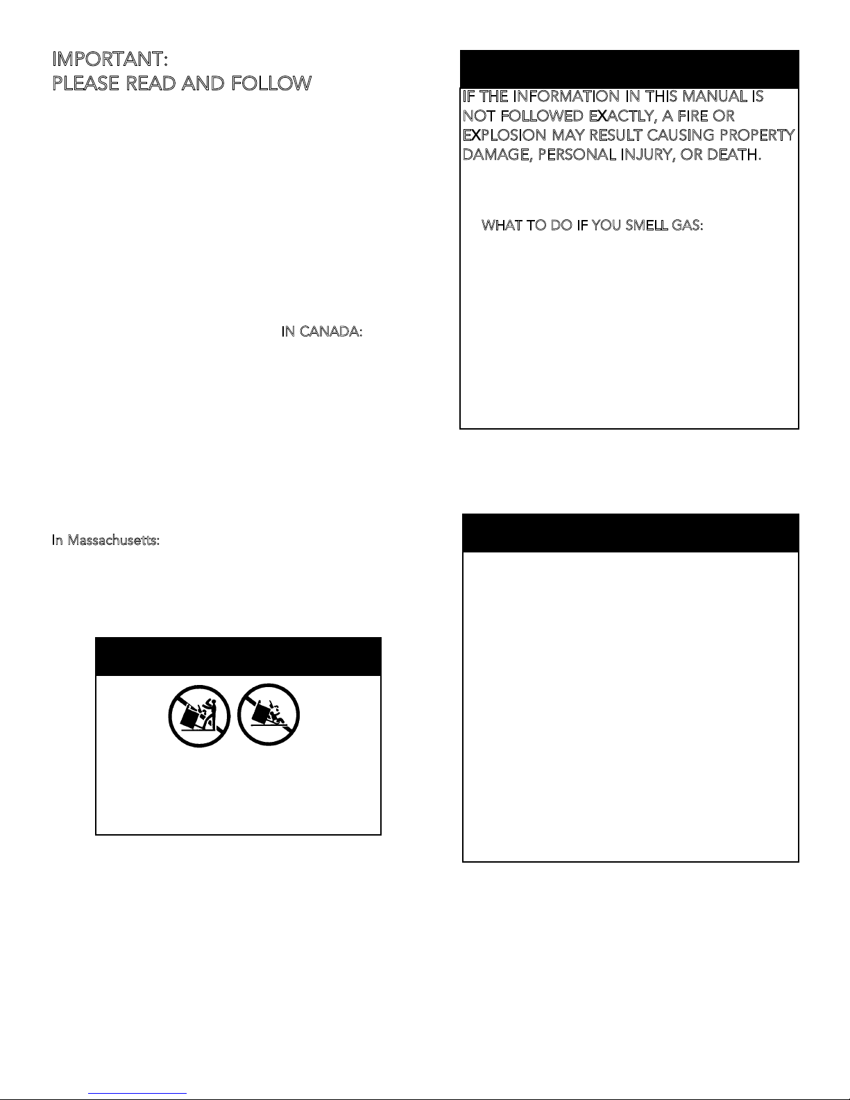
•This range can tip.
•Injury to persons could result.
•Install anti-tip device packed with range.
•See Installation Instructions
WARNING
If not installed, operated and maintained in
accordance with the manufacturer’s instructions,
this product could expose you to substances in fuel
or from fuel combustion which can cause death or
serious illness and which are known to cause
cancer, birth defects, or other reproductive harm.
For example, benzene is a chemical which is
part of the gas supplied to the cooking
product. It is consumed in the flame during
combustion. However exposure to a small
amount of benzene is possible if a gas leak
occurs. Formaldehyde and soot are byproducts of incomplete combustion. Properly
adjusted burners with a bluish rather than
yellow flame will minimize incomplete
combustion.
1
Page 3
GENERAL INFORMATION
ARNING:
W
•
appliance may result in a potential burn hazard.
Combustible items may ignite, metallic items may become
hot and cause burns. If a cabinet storage is to be provided
the risk can be reduced by installing a rangehood that
projects horizontally a minimum of 5” (12.7 cm) beyond the
bottom of the cabinets.
ARNING:
W
•
heating. This information is based on safety
considerations.
•All openings in the wall behind the appliance and in the
floor under the appliance shall be sealed.
•Keep appliance area clear and free from combustible
materials, gasoline, and other flammable vapors.
•Do not obstruct the flow of combustion and ventilation air.
•Disconnect the electrical supply to the appliance before
servicing. The power disconnect for the sealed top
units is located behind the lower access panel of the
range. This should only be removed by a qualified
service technician.
•When removing oven for cleaning and/or service;
•Electrical Requirement
Listed on Specification sheet. Electrical installation should
comply with national and local codes.
•Gas Manifold Pressure:
•Flexible Connections:
If this unit is to be installed with flexible couplings and/or
quick disconnect fittings, the installer must use a flexible
connector of at least 1/2” ID (1.3 cm) NPT with suitable
strain reliefs and comply with ANSI Z21.41 and Z21.69
standards.
•The misuse of oven doors (e.g. stepping, sitting, or leaning
on them) can result in potential hazards and/or injuries.
The use of cabinets for storage above the
This appliance shall not be used for space
A. Shut off gas at main supply
B. Disconnect AC power supply
C. Disconnect gas line to the inlet pipe.
D. Carefully remove the range by pulling outward.
Natural gas 5.0” W.C.P.
LP/Propane 10.0” W.C.P.
WARNING
ELECTRICAL GROUNDING INSTRUCTIONS
This range must be electrically grounded in
accordance with local codes, or in the absence of
local codes, with the National Electrical Codes,
ANSI/NFPA 70-latest edition. This appliance is
equipped with a three-prong plug for your
protection against shock hazard and should be
plugged directly into a properly grounded
receptacle. Do not cut or remove the grounding
prong from this plug. Do not connect product to
m
GFI circuit. The
proper operation of gas ignition systems. Prior to
servicing, disconnect appliance electrical supply.
For sealed top units the power disconnect is
located behind the lower access panel. This
should only be removed by a qualified service
technician.
F
OR PERSONAL SAFETY, THIS APPLIANCE MUST
inimum
BE PROPERLY GROUNDED
of 102VAC is required for
BACK TRIM ACCESSORIES
Assembly and installation instructions are included
with all back trim accessories.
LEGS
•Legs are packed in styrofoam top pack.
•Legs should be installed near to where the appliance is to
be used, as they are not secure for long transit. After
unpacking the range, raise it about a foot to remove the
bottom shipping skid. Keep the unit raised to permit the
legs to be screwed into our couplings and lower it gently
to keep any undue strain from the legs and internal
mounting hardware. It is strongly recommended that a
pallete or lift jack be used rather than tilting.
N
OTE:
If legs are removed from range and range rests on a
combustible surface, warranty and CSA certification
are void.
2
Page 4
BASIC SPECIFICATIONS VGIC
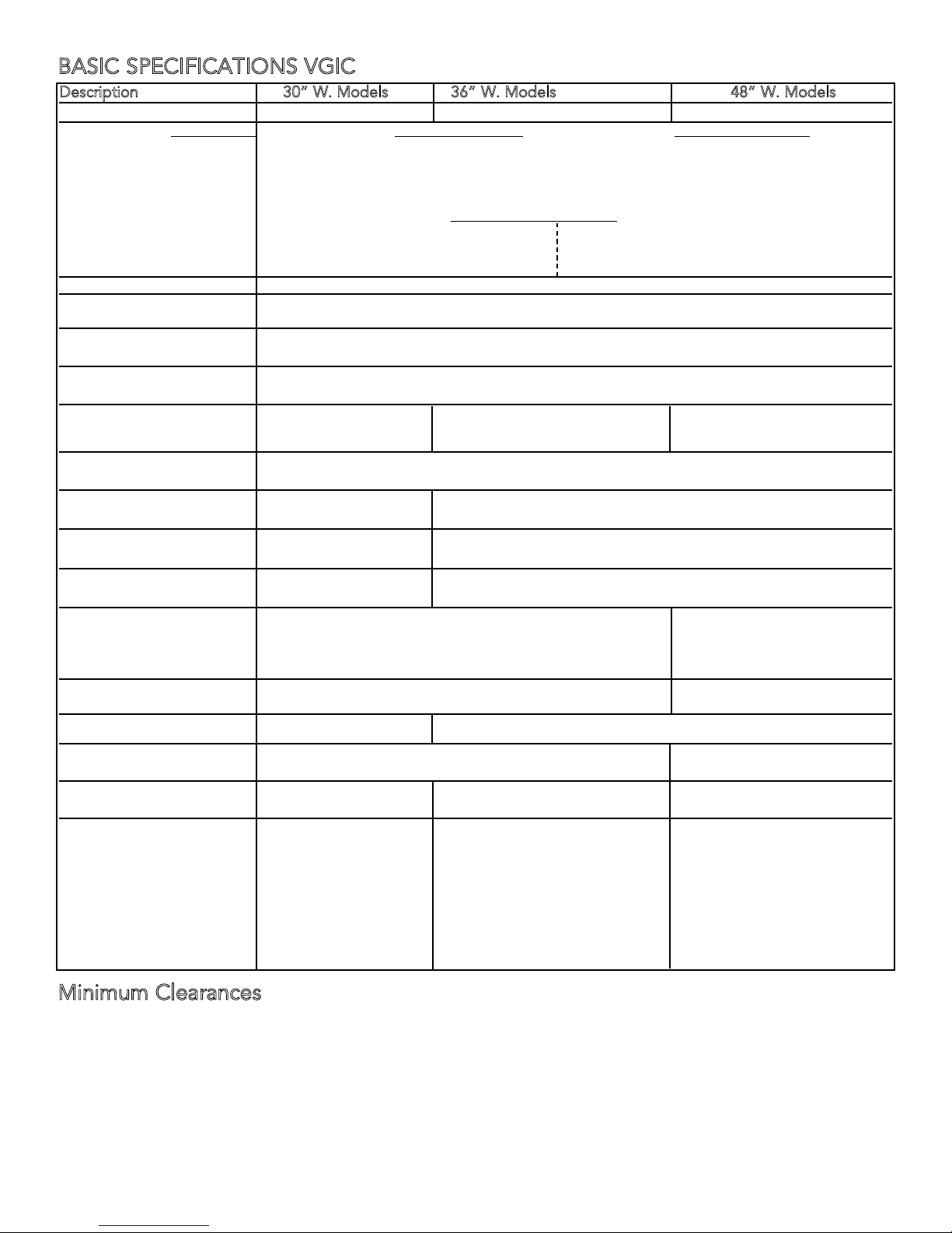
Description 30” W. Models 36” W. Models 48” W. Models
Overall width 29 7/8” (75.9 cm) 35 7/8” (91.1 cm) 47 7/8” (121.6 cm)
Overall height Base Height Open Top Burners Sealed Top Burners
To top of: grate support - burner grate -
Min. 35 7/8 “ (91.1 cm) 37 3/8” (94.9 cm)
Max. 37 5/8” (95.6 cm) 39 1/8” (99.4 cm)
Legs adjust 1 3/4” (4.5 cm) 1 3/4” (4.5 cm)
Additions to Base Height
To top of spider grate - add 1 1/8” (2.9 cm) To top of 10” backguard - add 10” (25.4 cm)
To top of island trim - add 1 1/4” (3.2 cm) To top of high shelf - add 23 1/2” (59.7 cm)
To top of 6” backguard -add 6” (15.2 cm)
Overall depth from rear To end of side panel - 24 15/16” (63.3 cm)
To end of control panel - 27 7/8” (70.8 cm)
To end of knobs - 28 3/8” (72.0 cm)
Electrical requirements 120 VAC/60 Hz; 4 ft. (121.9 cm), 3-wire cord with grounded 3-prong plug attached to
unit.
Gas requirements Shipped natural or LP/Propane gas; field convertible with conversion kit (purchased
separately); accepts standard residential 1/2” (1.3 cm) ID gas service line.
Maximum amp usage .83 amps 6B - .83 amps 6G / 4GQ / 4K - 1.52 amps
4G - .96 amps 6Q / 4Q / 8B - 1.52 amps
4Q - .83 amps 4G - 1.89 amps
Surface burner rating 15,000 BTU Nat. / 13,500 BTU LP
(4.4 kW Nat / 4.0 kW LP)
Griddle burner rating 15,000 BTU Nat. / 13,500 BTU LP
N/A (4.4 kW Nat. / 4.0 kW LP)
Grill burner rating 12” - 1@ 18,000 BTU Nat. (5.3 kW)/ 16,000 BTU LP (4.7 kW)
N/A 24” – 2 @ 15,000 BTU Nat. (4.4 kW)/ 13,500 BTU LP (4.0 kW)
Broil rating 18,000 BTU Nat./ 16,000 BTU LP
(5.3 kW Nat. / 4.7 kW LP)
Bake rating 30,000 BTU Nat./LP Right 30,000 BTU Nat./LP
(9.8 kW Nat./LP) (9.8 kW Nat./LP)
Left 15,000 BTU Nat/LP
(4.4 kW Nat.)
Oven Interior width 23” (58.4 cm) 29” (73.7cm) Right - 23” (58.4 cm)
Left - 12 1/8” (30.8 cm)
Oven Interior height 16 1/8” (41.0 cm)
Oven Interior depth 17” (43.2 cm) Right- 17”(43.2 cm)
Left - 18 1/8”(45.9 cm)
Oven Interior overall size 3.7 cu. ft. 4.6 cu. ft. Right - 3.7 cu. ft.
Left - 2.0 cu. ft.
Approximate Shipping wt.
424 lbs. (190.8 kg) 6B - 465 lb. (209.3 kg) 6G - 624 lb. (280.8 kg)
4Q - 470 lb. (211.5 kg) 6Q - 620 lb. (279.0 kg)
4G - 475 lb. (213.8 kg) 4G - 634 lb. (285.3 kg)
4Q - 620 lb. (279.0 kg)
4GQ - 629 lb. (283.1 kg)
4K - 624 lb. (280.8 kg)
8B - 620 lb. (279.0 kg)
Minimum Clearances
Minimum clearances from the product to adjacent surfaces or construction:
• Below 36” (91.4 cm)
Sides - 0”
Rear - 0”
• Above 36” (91.4 cm)
Sides - 6” (15.2 cm)
Within the 6” (15.2 cm) side clearance, wall cabinets shall be no deeper than 13” (33.0 cm) and must be a
minimum of 18” (45.7 cm) above the countertop.
3
Page 5
Minimum Clearances (cont.)
Rear - 0” with backguard or high shelf
0” with island trim and non-combustible heat resistant rear wall
6” (15.2 cm) with island trim and combustible rear wall
• Wall cabinets directly above the product must be minimum of 36” (91.4 cm) above the countertop for open top
burners and 42” (106.7 cm) for sealed burners.
To maintain product warranty, the responsibility for ensuring the use of non-combustible heat resistant materials when
required, lies with individual owner, contractor or end user.
*
Use range only with factory supplied legs.
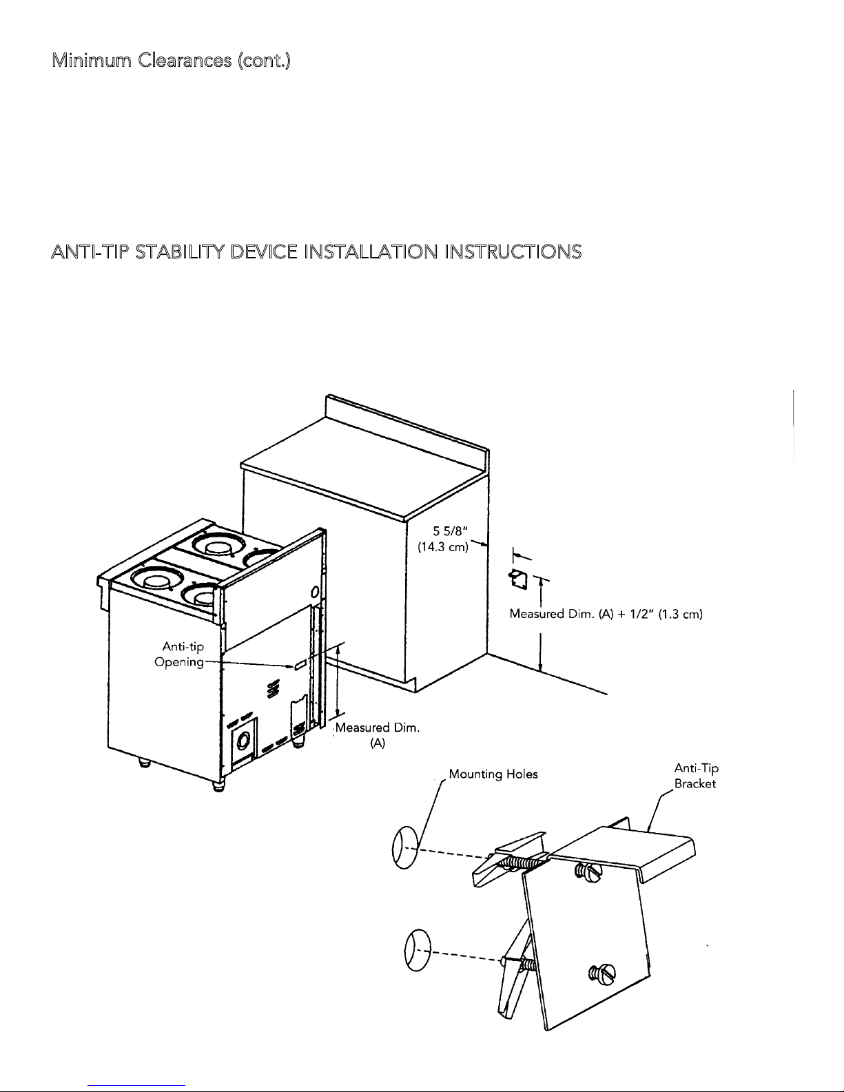
ANTI-TIP STABILITY DEVICE INSTALLATION INSTRUCTIONS
1. The anti-tip bracket is to be attached to the rear wall as shown. The dimension for the bracket location from the
floor is to be determined after the range legs have been adjusted to the proper installation height shown in the
installation instructions and the range has been leveled.
2. Measure from the floor to the bottom of the anti-tip opening located on the back of the range.
3. Locate the anti-tip bracket on the wall at the measure dimension plus 1/2” (1.3 cm) from the floor and 5 5/8” (14.3
cm) from where the left side of the range (facing range) is to be located.
4. Slide range into place making sure the anti-tip bracket slides into the anti-tip opening.
4
Page 6
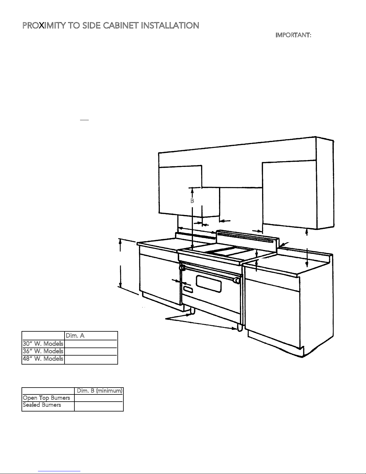
PROXIMITY TO SIDE CABINET INSTALLATION
MPORTANT:
1. This range may be installed directly adjacent to existing 36” (91.4 cm) high base cabinets.
grate support MUST be 3/8” (.95 cm) above the adjacent base cabinet countertop. This may be accomplished by
raising the unit using the adjustment spindles on the legs.
2. The range CANNOT be installed directly adjacent to sidewalls, tall cabinets, tall appliances, or other side vertical
surfaces above 36” (91.4 cm) high. There must be a minimum of 6” (15.2 cm) side clearance from the range to such
combustible surfaces above the 36” (91.4 cm) counter height.
3. Within the 6” (15.2 cm) side clearance to combustible vertical surfaces above 36” (91.4 cm) , the maximum wall
cabinet depth must be 13” (33.0 cm) and wall cabinets within this 6” (15.2 cm) side clearance must be 18” (45.7 cm)
above the 36” (91.4 cm) high countertop.
4. Wall cabinets above the range must be a minimum of 36” (91.4 cm) for open top burner units and 42” (106.7 cm)
for sealed top burner units above the range cooking surface for the full width of the range. This minimum height
requirement does not
apply if a rangehood is installed over the cooking surface.
I
The top
30” W. Models
36” W. Models
4
8” W. Models
(91.4 cm)
Dim. A
29 7/8” (75.9 cm)
35 7/8” (91.1 cm)
47 7/8” (121.6 cm)
36”
6” Minimum
(15.2 cm)
0” (0.0 cm)
Adjustment
Spindles
B
13” Maximum
(33.0 cm)
A
0”
(0.0 cm)
3/8” (.95 cm)
18” Minimum
(45.7 cm)
Dim. B (minimum)
Open Top Burners
Sealed Burners
36” (91.4 cm)
42” (106.7 cm)
5
Page 7
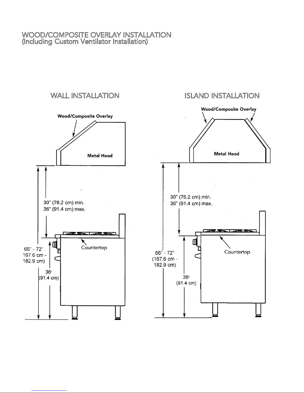
WOOD/COMPOSITE OVERLAY INSTALLATION
(Including Custom Ventilator Installation)
The bottom of a standard hood should be 30” (76.2 cm) min. to 36” (91.4 cm) max. above the countertop. This
would typically result in the bottom of the hood being 66” (167.6 cm) to 72” (182.9 cm) above the floor. Refer to
the rangehood installation instructions for additional information. These dimensions provide for safe and efficient
operation of the hood.
WALL INSTALLATION
ISLAND INSTALLATION
6
Page 8
When installing or removing the range for service, a rolling lift jack should be used. Do not push against any of the
edges of the range in an attempt to slide it into or out of the installation. Although all metal parts are deburred during
manufacturing, accidents could occur if the range should be moved suddenly or violently. Pushing or pulling a range
(rather than using a lift jack) also increases the possibility of bending the leg spindles or the internal coupling
connectors.
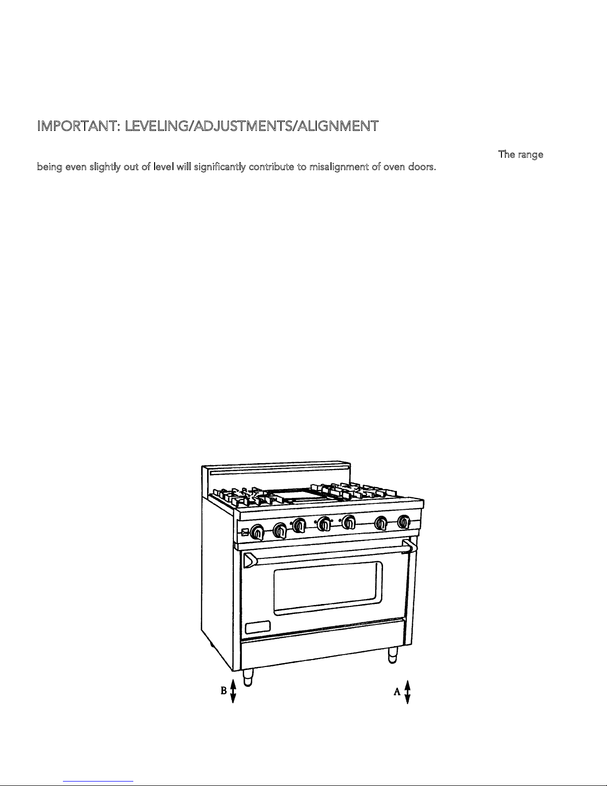
IMPORTANT: LEVELING/ADJUSTMENTS/ALIGNMENT
Careful leveling of the range is critical not only to performance, but also to allow the alignment of oven doors and drip
he range
tray. Closely follow the procedures below to ensure proper performance and appearance of the range.
being even slightly out of level will significantly contribute to misalignment of oven doors.
1. If the floor is smooth and level, level the unit with the screw thread of the legs. Set the high corner of the range so
that the the top of the grate support is 3/8” (.95cm) above the countertop, and level the range to the high corner.
2. If the floor is uneven or has a decided slope, level the unit with metal shims, as the adjustment required may exceed
the thread available in the leg.
3. Proper and careful leveling of the range is necessary for proper alignment of the oven doors. The body of the
range does not have a rigid frame to hold it into one position. This nonrigid framework allows the range to shift
with unlevel floors or slanted cabinets. Moving any one of the adjustable leveling legs up or down will shift the
range body. Increasing the length of the right front leveling leg will raise the right front corner of the range, moving
the top of the door to the left. Lowering the right front leveling leg will cause the tip of the door to move to the
right. Using the left front leveling leg will give you the opposite effect. Raising the left front corner will move the
top of the door to the right. Lowering the corner will move the top of the door to the left. The rear leveling legs
will also have an effect on the door alignment.
4. After the range is properly leveled, the drip tray handle may be aligned by loosening the screws and adjusting the
handle horizontally within the limits provided by the slotted screw holes.
5. A level should be placed across the top of the range and the unit leveled both front-to-back and side-to-side. If it is
not level, burner combustion may be erratic, liquid, or semi-liquid batters will cook at an angle, and the unit may
not function efficiently.
T
A. Right Side
Front / Back
Adjustable Legs
B. Left Side
Front / Back
Adjustable Legs
7
Page 9
GAS CONNECTION
All gas connections must be made according to national and local codes. This gas supply (service) line must be the
same size or greater than the inlet line of the appliance. This range uses an ISO7 or ISO128 inlet. The inlet depends
on the end users national and local codes.
anual Shut-off Valve:
M
1.
This installer-supplied valve must be installed in the gas service line ahead of the appliance in the gas stream and in
n Massachusetts:
a position where it can be reached quickly in the event of an emergency.
manual valve must be installed in the gas supply line to the appliance.
2. Pressure Regulator
a) All heavy duty, commercial type cooking equipment must have a pressure regulator on the incoming service
line for safe and efficient operation, since service pressure may fluctuate with local demand. External
regulators are not required on this range, because a regulator is built into each unit at the factory. Under no
condition bypass this built-in regulator.
b) Any conversion required must be performed by your dealer or a qualified licensed plumber or gas service
company. Please provide the service person with this manual before work is started on the range. (Gas
conversions are the responsibility of the dealer or end user.)
c) This range can be used with Natural or LP/Propane gas. It is shipped from the factory adjusted for use with
either natural gas or LP. To convert a natural gas range to LP/Propane, you will need the LPKSBRR (Sealed
Burner) or LPKRR (Open Burner) Kit.
d) Manifold pressure should be checked with a manometer, natural gas requires 5.0” W.C.P. and LP/Propane
requires 10.0” W.C.P. Incoming line pressure upstream from the regulator must be 1” W.C.P. higher than
the manifold pressure in order to check the regulator. The regulator used on this range can withstand a
maximum input pressure of 1/2 PSI (14.0” W.C.P.) If the line pressure is in excess of that amount, a stepdown regulator will be required.
e) The appliance, its individual shut-off valve, and pressure regulator must be disconnected from the gas
supply piping system during any pressure testing of that system at pressures in excess of 1/2 psig (3.45 kPa).
f) The appliance must be isolated from the gas supply piping system by closing its individual manual shut-off
valve during any pressure testing of the gas supply piping system at test pressures equal to or less than 1/2
psig (3.45 kPa).
I
A “T” handle type
lexible Connections:
F
3.
a) If the unit is to be installed with flexible couplings and/or quick disconnect fittings, the installer must use a
heavy-duty, AGA design-certified commercial flexible connector of at least 1/2” (1.3 cm) ID NPT (with
suitable strain reliefs) in compliance with ANSI Z21.41 and Z21.69 standards.
n Canada
I
b)
device for use with gas fuel.
I
n Massachusetts:
c)
AUTION:
C
placing the oven into operation, always check for leaks with a soapy water solution of other acceptable method. DO
NOT USE AN OPEN FLAME TO CHECK FOR LEAKS!
Leak testing of the appliance shall be conducted according to the manufacturer’s instructions. Before
: CAN 1-6.10-88 metal connectors for gas appliances and CAN 1-6.9 M79 quick disconnect
This appliance must be installed with a 36” (3-foot) long flexible gas connector
8
Page 10
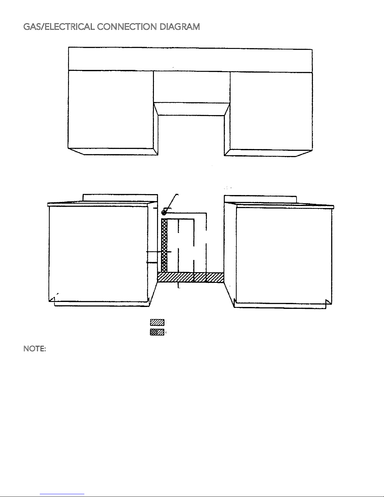
GAS/ELECTRICAL CONNECTION DIAGRAM
2” (5.1 cm)
Dia.
2 3/4” (7.0 cm)
NOTE:
31 1/16”
(78.9 cm)
28 5/16”
(71.9 cm)
2 1/2”
(6.4 cm)
1 3/4”
(4.4 cm)
23 7/16”
(59.5 cm)
4 3/8”
(11.1 cm)
Electrical Connection in this area
Gas Connection in either area
If the gas supply is installed through the rear wall, the location MUST be 31 1/16” (78.9 cm) above the floor
and 2 3/4” (7.0 cm) from the left hand side (when facing the unit) or within a maximum of 4 3/8” (11.1 cm)
above the floor as specified in the drawing above.
9
Page 11
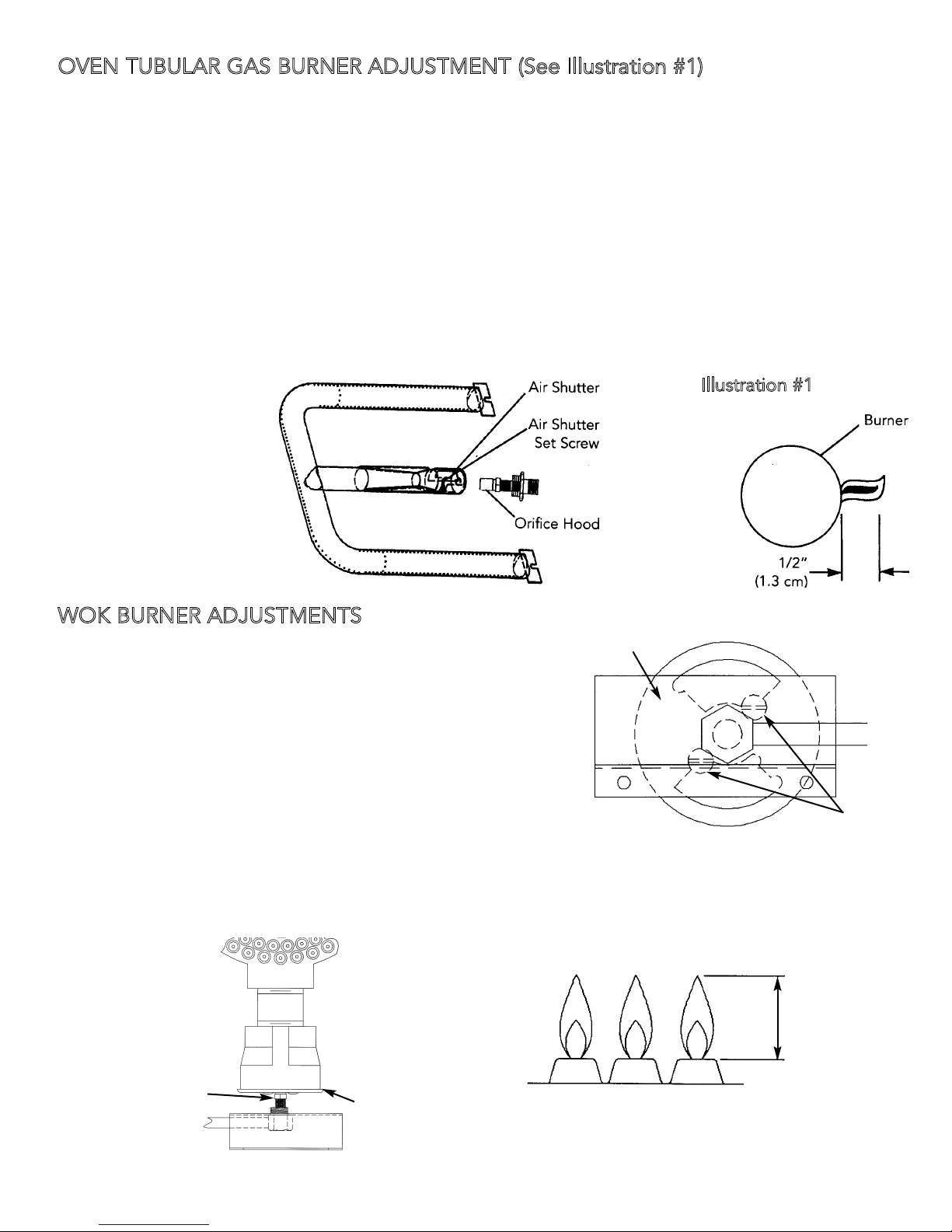
OVEN TUBULAR GAS BURNER ADJUSTMENT (See Illustration #1)
Check the gas supply, and set the regulator to proper supply of gas. A properly adjusted burner should be stable and
quiet. The flame should have a sharp, well defined blue inner cone with no yellow tipping. The flame should also be
stable and uniform with no flames lifting off the burner ports.
To gain access to the oven burner adjustments:
1. Remove oven bottom panel.
2. Remove U-shaped burner venturi cover.
3. Locate the air shutter and loosen the set screw that holds the air shutter in place.
4. Light the burners by rotating the thermostat to a baking temperature.
5. Adjust the air shutter to obtain a blue flame with no yellow tipping that contacts the burner at the burner ports.
a) Open the air shutter gap to eliminate yellow tipping.
b) Close the air shutter gap to prevent a noisy flame that lifts off the burner.
6. Turn the thermostat off.
7. Tighten the air shutter set screw being careful to not change the adjusted shutter gap.
Illustration #1
WOK BURNER ADJUSTMENTS
To gain access to the burner for adjustments:
1. Remove the grate and grate support.
2. Locate the air shutter “A” and loosen the two screws “B” that holds the
air shutter in place.
3. Light the burner and turn the burner knob to the high position.
4. With a proper, high flame height, adjust the air shutter to obtain a blue
flame with no yellow tipping that sits on the burner at the burner ports.
(a) open the air shutter gap to add more air and to eliminate yellow
tipping.
(b) close the air shutter gap to reduce the air and to prevent a noisy
flame that lifts off the burner.
5. Turn the surface burners off.
6. Tighten the air shutter screws.
7. Replace the grate support and grate.
OVERHEAD VIEW
A
AIR SHUTTER
FLAME HEIGHT
3
/4”
B
(1.91 cm)
Orifice
Air Shutter
10
Page 12
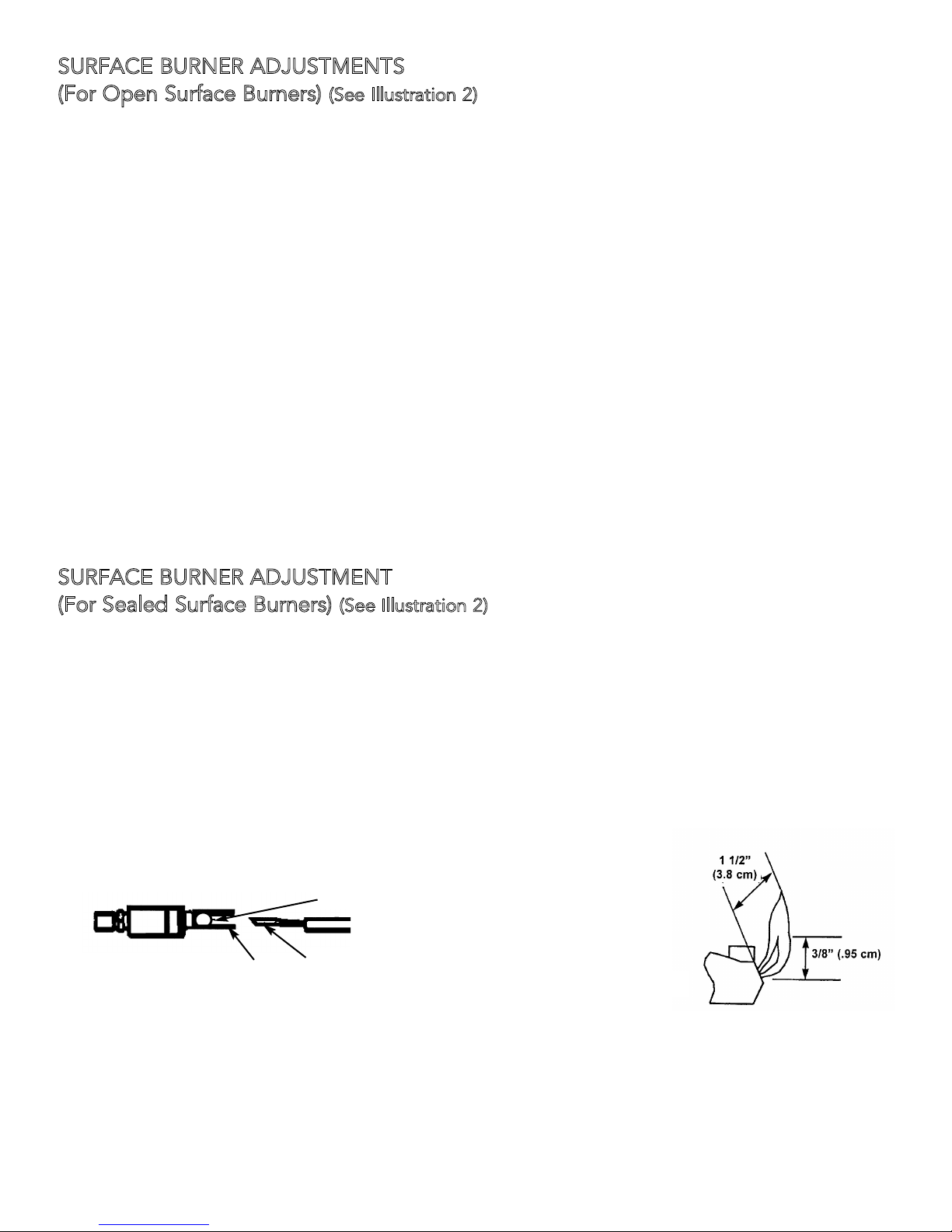
SURFACE BURNER ADJUSTMENTS
(For Open Surface Burners)
To gain access to the surface burner adjustments:
1. Remove the grates, burner caps, bowls and grate supports.
2. Located the air shutter (A) and loosen the screw (B) that holds the air shutter in place.
3. Replace grate support and burner bowls (this allows for correct air flow, as in normal use).
4. Light each burner by rotating the burner valve shaft (D) to high position.
5. With a proper flame height, adjust the air shutter (A) to obtain a blue flame with no yellow tipping that sits on the
burner at the burner ports.
a) Open the air shutter gap to eliminate yellow tipping.
b) Close the air shutter gap to prevent a noisy flame that lifts off the burner.
6. Turn the surface burners off.
7. Replace the drip tray.
8. Remove grate support and burner bowls.
9. Tighten the air shutter screw (B) being careful to not change the adjusted shutter gap.
10. Replace the grate supports, burner bowls, burner caps, and grates.
11. Turn the lighted burners to the low flame setting.
12. Insert a narrow, flat-blade screwdriver into the hollow shaft of the surface burner valve, and engage the slotted low
flame adjustment screw. The low flame should be a small flame that comes just to the top edge of the burner.
Rotate the adjusting screw (E) clockwise to lower the flame or counter clockwise to increase the flame. Turn the
burner off and relight several times, turning to the low position. The low flame should light at every port each
time. Readjust as needed.
(See Illustration 2)
SURFACE BURNER ADJUSTMENT
(For Sealed Surface Burners)
1. Turn the lighted burners to the low flame setting. Remove the knob.
2. Insert a narrow flat-blade screwdriver into the hollow shaft of the surface burner valve located behind the control
knob and engage the slotted low flame adjustment screw. The low flame should be a small flame that comes just to
the top edge of the burner. Rotate the adjusting screw clockwise to lower the flame or counter-clockwise to
increase the flame. Turn the burner off and relight several times, turning to the low position. The low flame should
light at every port each time. Readjust as needed.
Surface burner valve
(behind control knob)
(See Illustration 2)
Flame adjustment
screw
Flathead
screwdriver
Flame Height
11
Page 13
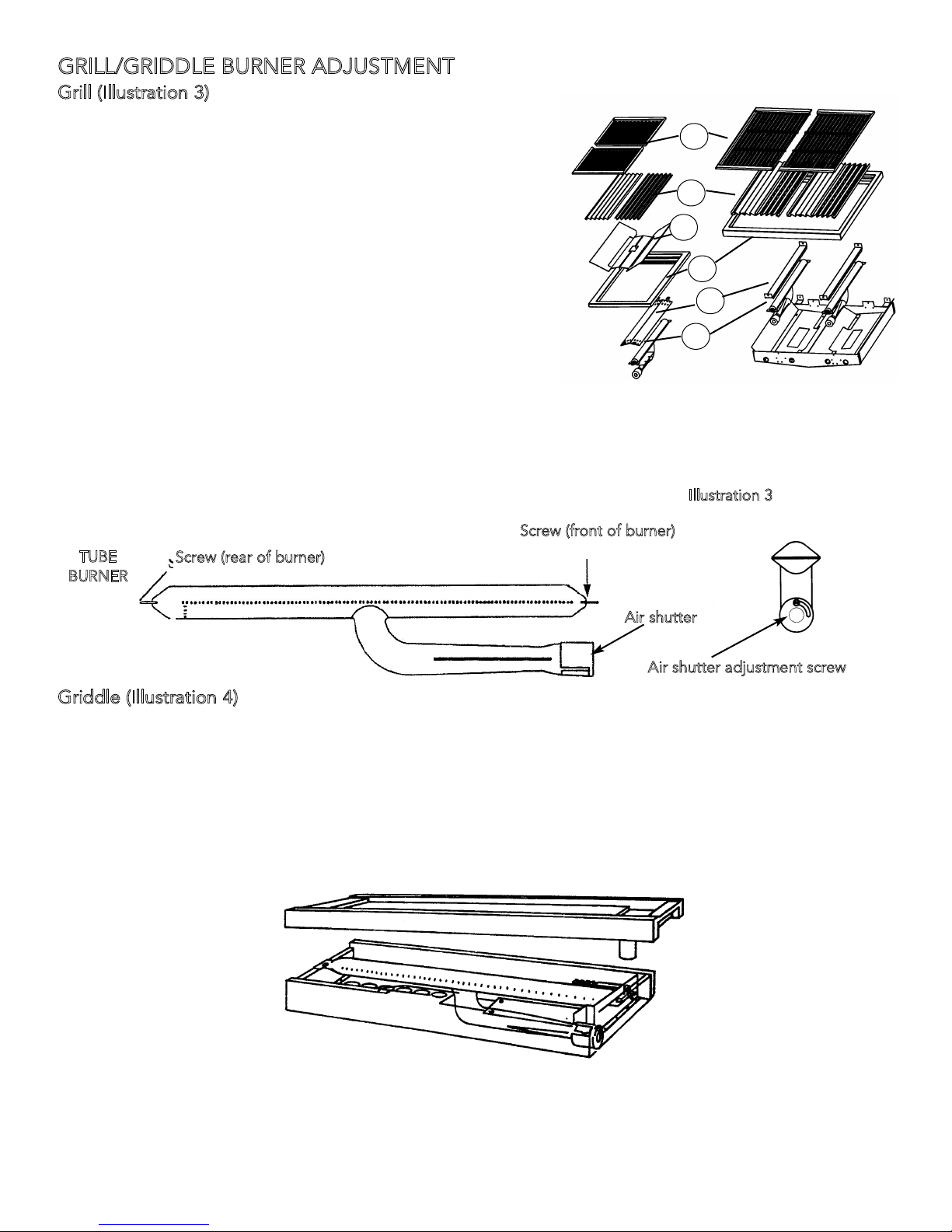
GRILL/GRIDDLE BURNER ADJUSTMENT
Grill (Illustration 3)
1. The grill burner orifice and air shutter are located beneath the front
end of the grill assembly. To gain access to the adjsutments,
remove the grill grate, flavor generator plates, grate support, and
the burner shield.
2. Remove the screw at the front and rear of the burner.
3. Lift the tube burner off the orifice and locate the air shutter
adjustment screw at the end of the burner.
4. Loosen the screw and adjust the air shutter to the desired setting.
(for natural gas open shutter approximately 7/16” [1.1 cm]; for
LP/Propane gas open the air shutter approximately 3/8” [0.98 cm]).
5. Tighten the screw, then replace tube burner on orifice.
6. Check flame for desired height before replacement of the above
parts.
7. Open the air shutter gap to eliminate yellow tipping.
8. Close the air shutter gap to prevent a noisy flame that lifts off the
burner.
12” Grill Assembly 24” Grill Assembly
1
2
3
4
5
6
1. Grill Grates
2. Flavor Generator
plates
3. Heat Deflector
4. Grill Frame
5. Grill Burner Sheild
(Do not remove
from burner)
6. Burner
(Do not remove)
Illustration 3
Screw (front of burner)
TUBE
Screw (rear of burner)
BURNER
Air shutter
Air shutter adjustment screw
Griddle (Illustration 4)
1. To gain access to the air shutter, remove grates and grate supports located on either side of the griddle. Lift and
remove griddle.
2. Remove the metal plate located below the burner.
3. Remove the screws at the front and rear ofthe burner, remove the burner tube and locate the air shutter adjustment
screw at the end of the burner tube.
4. Flame adjustments are the same as grill - see #4-#7 under Grill.
5. Replace all griddle parts, griddle, grate supports, and grates.
12
Page 14
DSI SPARK MODULE SPECIFICATIONS
Power Requirements
Input Voltage range (L1-N) 102 to 132 VAC, 60/50 Hz 135 mA current typical
C
ontrol Outputs
Bake or Broil Burner
Coil Pull-in pulse 54VDC +
Coil Hold-in 36 mA minimum
Life Requirements 2000,000 cycles
Bake and Broil Spark: 16.5 KV @ 50 PFD load @ nominal conditions
Design Life 2,000,000 sparks
Spark Rate 3 sparks then 1 second delay (repeated Cadence)
ontrol Inputs
C
Flame Sense Type: Flame Rectification
Minimum Flame Sense: 1µA. min.
Flame Sense Model: A 25 MΩ resistor in series with a 1N4004 diode
C
ontrol Timing
All timings are 60 Hz; timings will be 20% longer at 50 Hz. Times are +/- 0.2 seconds except for flame failure response
time.
Trial for ignition period 10.0 sec Flame failure response time: 30.0 sec max.
Lock out time: 15.0 sec Flame establishing period: 0.5 sec
Conditional prepurge time: 30.0 sec Recycle time: 30.0 sec
Interpurge time: 30.0 sec Ignition attempts: 3
10% @ 250mA
Ignition recycles: 1
escription of Operation
D
Overview
The GDS/DSI control interfaces with a thermostat, a valve, and spark electrodes to provide a complete direct spark
ignition system for gas ranges. The DSI is a 0 + 2 DSI system: 2 oven burner spark outputs with flame sense and valve
enable safety supervision. Contact closure inputs from the thermostat initiates micro controlled logic, which supervises
gas distribution to an oven burner and the ignition/flame sense safety circuits.
O
ven Burner Ignition
Closure of the thermostat output contacts (BR and/or BA) applies L1 to the Broil (J1-7) and/or Bake (J1-6) inputs. The
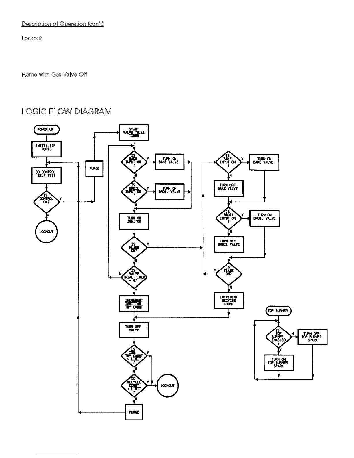
Bake and/or Broil input is detected by the micro, which operates the gas valve and spark ignition sequence. The Logic
Flow Diagram and Timing Diagram illustrates the typical valve/ignition supervision sequence provided by the micro as
follows:
Power up initializes the micro ports and performs an internal self-test and a flame safety check. Failure of this
test sequence aborts operation in the lockout mode, which safety inhibits gas flow and sparking to prevent
ignition of any residual gas.
Verification of the safety checks initiates the Valve Trial Timer, which energizes the bake or broil solenoid. The
spark output rate is coordinated to the flame sense sequence, confirmation of flame sense typically occurs after
2 sparks. If flame is detected, the spark is inhibited, and the valve will be enabled/opened as long as flame
sense is normal and a call for heat is detected. If flame is not detected, the spark rate will continue for the full
duration of Valve Trial Time. Combustion failure during the ignition trial period or after the flame has been
established, will de-energize the solenoid for a 30-second interpurge time before initiating another trial for
ignition. If the control fails to establish proof of flame after a specified number of ignition attempts, the
external lockout is executed.
13
Page 15
Description of Operation (con’t)
Lockout
The control will lockout if any self-checks fail during normal operation. Also, the control will lockout if it failed to ignite
gas after the selected number of ignition attempts or ignition recycles. In lockout the valve and ignition means are
turned off. The control must be manually reset by cycling bake or broil off and back on.
lame with Gas Valve Off
F
If there is proof of flame for ten seconds with the gas valve off, the control will go to lockout. If there is flame for less
than ten seconds, the control will reset.
LOGIC FLOW DIAGRAM
14
Page 16
TIMING DIAGRAM: NORMAL IGNITION CYCLE
TIMING DIAGRAM: POWER UP CYCLE - IGNITION, FLAME LOSS
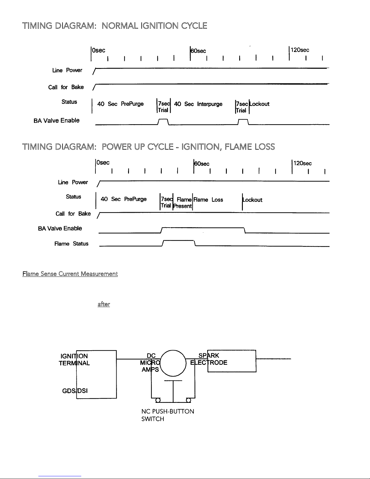
Flame Sense Current Measurement
Local Sense:
Connect a DC Micro-amp meter in series with the high voltage lead and the spark electode wire as shown.
fter
a
Push switch to read current
LOCAL SENSING: CONNECT DC MICRO-AMP METER IN SERIES WITH HIGH VOLTAGE LEAD AS SHOWN
flame is established and the spark output is de-energized.
PUSH SWITCH TO READ CURRENT AFTER FLAME
IS ESTABLISHED AND SPARKING CEASES
15
Page 17
INITIAL IGNITION OF BURNERS
All ovens are tested before leaving the factory. When the oven is connected to the gas supply and the electrical
OTE:
service, the installer should use the “Performance Checklist” for his final checks.
direct spark ignition system for both bake and boil burners. On initial power up, there will be a 30-60 second delay for
the electronics to reset before ignition.
When adjustments are required, contact your dealer/installer for corrections. If assistance is not available, contact
Viking Range Corporation Preferred Service for the nearest authorized service agent at (888) 845-4641. All corrections
to installation are the responsibility of the dealer/installer or end user.
N
This model is equipped with a
REPLACEMENT PARTS
Only authorized replacement parts may be used in performing service on the oven. Replacement parts are available
from factory authorized parts distributors. Contact Viking Range Corporation Preferred Service, (888) 845-4641, for the
nearest parts distributor in your area.
PERFORMANCE CHECKLIST
The installer should carry out the following performance checks. Refer to instructions below.
1. Check open top burner ignition.
2. Check air shutter adjustment - sharp blue flame, no yellow tipping. (See “Surface Burner Adjustment”)
3. Check low flame adjustment - surface burner valve center stem adjustment.
4. Check griddle ignition - all burner ports.
5. Cycle griddle burner.
6. Check air shutter adjustment - sharp blue flame, no yellow tipping. (See “Grill/Griddle Burner Adjustment”)
7. Check grill ignition - all burner ports.
8. Check air shutter adjustment - sharp blue flame, no yellow tipping. (See “Grill/Griddle Burner Adjustment”)
9. Check low flame adjustment - grill valve center stem adjustment.
10 . Visually check tubular burner reignition to be sure both sides are relighting each time.
11. Check for gas leaks (odors) at all gas connections.
OTE:
12. Check oven bake and convection bake function.
system for both bake and broil burners. On initial power up, there will be a 30-60 second delay for the electronics
to reset before ignition.
13. Check self-clean function - door will lock and in approximately 30 seconds and the broil burner will ignite. If there
is excess air in the gas line, the electrode will not sense flame and will shut-off gas to the burner. Wait 30 seconds
AUTION:
and re-try ignition.
supports inside oven. This could cause them to discolor due to the high temperature required for self-cleaning.
C
Do not run self-clean cycle for more than 10 minutes with oven racks and rack
N
This model is equipped with a direct spark ignition
FINAL PREPARATION
1. Some stainless steel parts may have a plastic protective wrap which must be removed. The interior of the oven
should be washed thoroughly with hot, soapy water to remove film residues and any installation dust or debris
before being used for food preparation, then rinsed and wiped dry. Solutions stronger than soap and water are
rarely needed.
2. All stainless steel body parts should be wiped with hot, soapy water and with a liquid cleaner designed for this
material. If buildup occurs, do not use steel wool, abrasive cloths, cleaners, or powders! If it is necessary to scrape
stainless steel to remove encrusted materials, soak with hot, wet cloths to loosen the material, then use a wood or
nylon scraper. Do not use a metal knife, spatula, or any other metal tool to scrape stainless steel! Scratches are
almost impossible to remove.
OTE:
N
beneath the drip tray in the rear corner of the burner box. Remove the right rear burner bowl and pull the drip tray
forward approximately 6” (15.2 cm).
These installation instructions should remain with the unit for future reference. The electrical diagram is located
16
Page 18

17
Page 19

18
Page 20
Viking Range Corporation
111 Front Street
Greenwood, Mississippi 38930 USA
(662) 455-1200
For product information,
call 1-888-VIKING1 (845-4641)
or visit the Viking Web site at
vikingrange.com
F20466A (061907J)
 Loading...