

Viking Designer DMOS200SS, DMTK271SS, DMTK301SS, Designer DMOS200, Designer DMTK271 Installation Instructions Manual
...
VIKING RANGE CORPORATION
Minimum Cutout Opening Width 24 3/8" (619.13 mm)
Maximum Cutout Opening Width 24 11/16" (627.06 mm)
14 5/16" (363.475 mm)
Minimum Cutout Opening Height 16 3/4" (425.5 mm)
Maximum Cutout Opening Height 17" (431.8 mm)
12 13/16" (325.4 mm)
Distance between holes 25 5/8" (650.75 mm)
Distance between holes 28 5/8" (727.3 mm)
15 29/32" (403.66 mm)
29/32" (23.4 mm)
Center Line
Floor Line of Cutout Opening
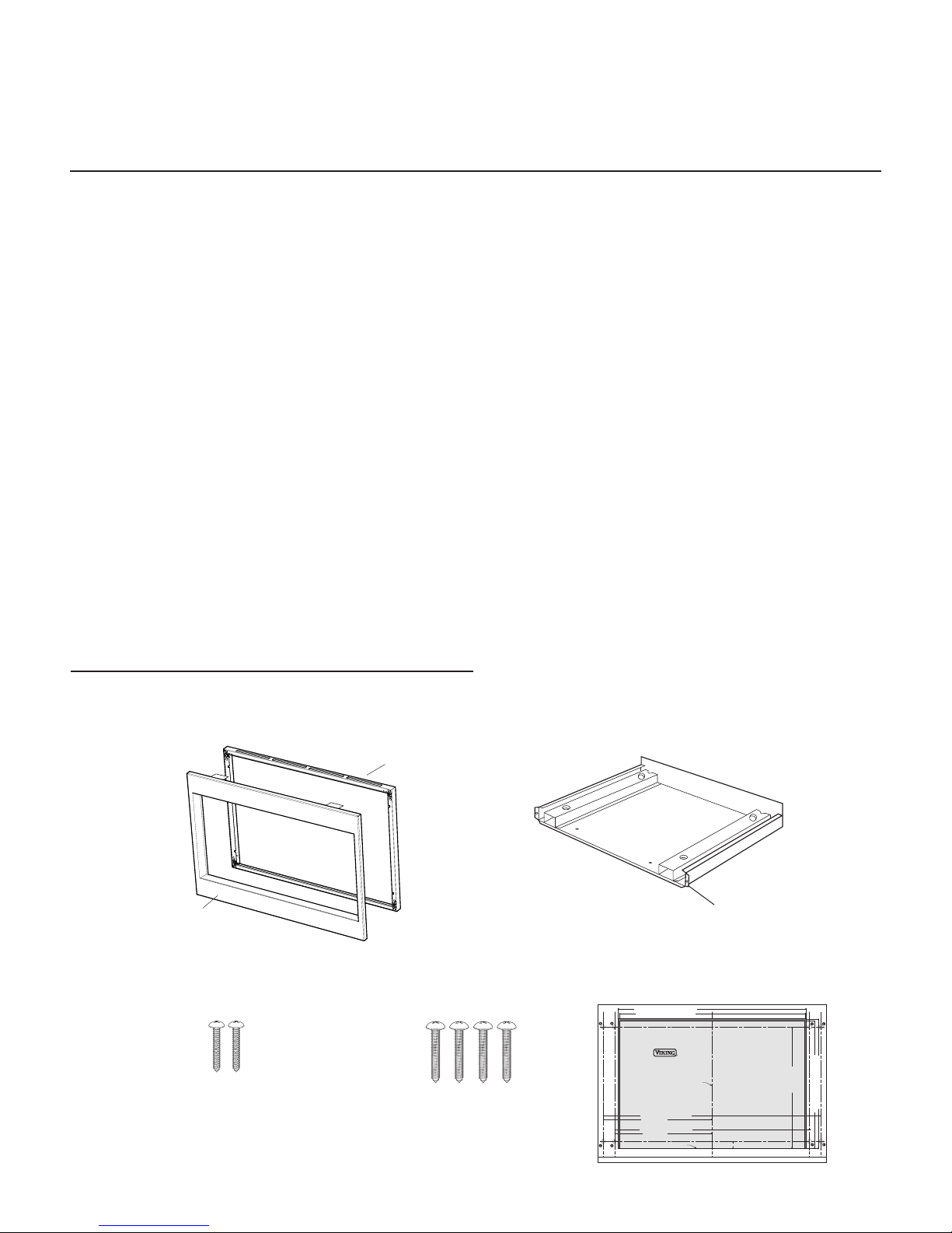
BUILT-IN TRIM KIT TEMPLATE
FOR DESIGNER SERIES MICROWAVE OVEN
1. Align the mounting template center line with the center of
the cutout and the floor line with the floor of the cutout.
Tape it into place.
2. For DMTK271, predrill 4 holes marked with a HP" drill bit.
For DMTK301, predrill 4 holes marked with a HP" drill bit.
3. Remove template from the cabinet
TINSKB110MRR0
INSTALLATION
Greenwood, Mississippi 38930 USA
111 Front Street
(662) 455-1200
INSTRUCTIONS
DESIGNER SERIES
MICROWAVE BUILT-IN TRIM KIT
Retain for Future Reference
IMPORTANT - PLEASE READ AND FOLLOW
• Before beginning, please read these instructions completely and carefully.
• Be sure to DISCONNECT THE PLUG of the microwave oven from the electrical outlet before installing the built-in trim kit.
Remove the turntable from the oven cavity.
• Because the kit includes metal parts, caution should be used in handling and installation to avoid the possibility of injury.
• Do not remove permanently affixed labels, warnings, or plates from the product. This may void the warranty.
• Please observe all local and national codes and ordinances.
• The installer should leave these instructions with the consumer who should retain for local inspector’s use and for future
reference.
THIS BUILT-IN TRIM KIT IS DESIGNED FOR USE ONLY WITH VIKING MICROWAVE OVENS SPECIFYING BUILT-IN
TRIM KIT DMTK271 OR DMTK301 ON THE RATING LABEL ON THE LEFT SIDE WALL OF THE OVEN CAVITY.
IF YOUR LOWER CONVENTIONAL OVEN IS NOT LISTED IN THE USE AND CARE MANUAL OF THE MICROWAVE
OVEN, THEN DO NOT INSTALL THE MICROWAVE OVEN ABOVE IT OR IN ANY AREA WHERE HEAT AND STEAM
ARE GENERATED; FOR EXAMPLE, NEXT TO OR ABOVE A CONVENTIONAL RANGE.
PARTS INCLUDED IN THE KIT
1) Frame Assembly
Back Frame
Front Frame
QTY 1
3) Screw A (1-3/16" length): QTY 2 4) Screw B (1 3/4" length): QTY 4
2) Bottom Duct Assembly: QTY 1
QTY 1
NOTE:
SIDE FL ANGES ON
DMTK3 01 ONLY.
5) Template: QTY 1
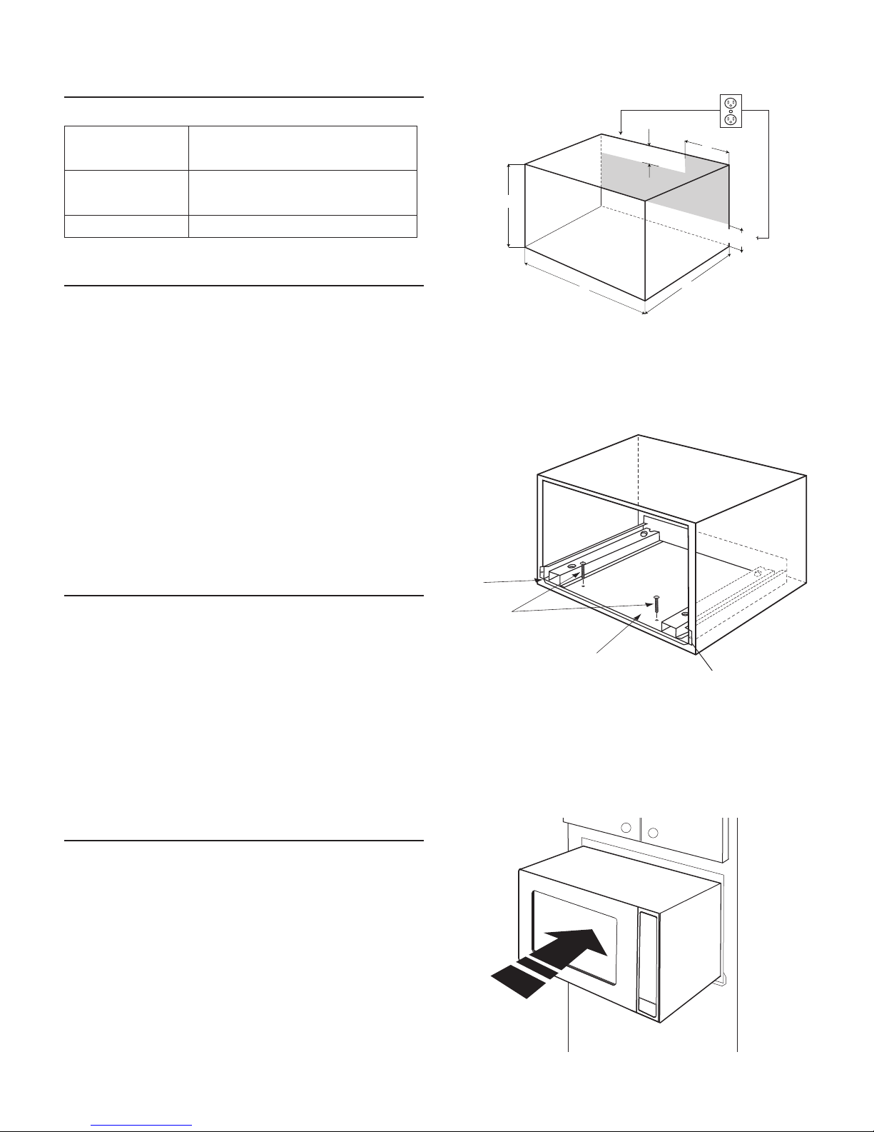
CABINET OR WALL CUTOUT
Cutout Dimensions
Height (A) Minimum 16 3/4" (42.5 cm)
Maximum 17" (43.2 cm)
Width (B) Minimum 24 3/8" (61.9 cm)
Maximum 24 11/16" (62.7 cm)
Depth (C) Minimum 20" (50.8 cm)
Illustration 1
6"(15.2 cm)
4"(10.2 cm)
A
4"(10.2 cm)
ELECTRICAL OUTLET LOCATION
Outlet should NOT be in the shaded area as indicated
on Illustration 1.
NOTE 1: If the Depth (C) dimension is greater than 21"
(53.3 cm), the outlet location may be in any area on the
rear wall.
NOTE 2: The floor of the opening should be constructed
of plywood strong enough to support the weight of the
oven and floor load (approximately 100 pounds). The
floor should be level for proper operation of the oven.
Be sure to check the local building code as it may require
that the opening be enclosed with side, ceiling and rear
partition. The proper functioning of the oven does not
require the enclosure.
MOUNTING TEMPLATE
1. Align the mounting template center line with the center
of the cutout and the floor line with the floor of the
cutout. Tape it into place.
2. For DMTK271, only predrill 4 holes marked “A” with
a 1/16" drill bit. For DMTK301, only predrill 4 holes
marked “B” with a 1/16" drill bit.
Illustration 2
MAKE FL ANGES
FLUSH
SCREW A
B
BOTTOM
DUCT ASSEMBLY
C
NOTE:
SIDE FL ANGES ON
DMTK3 01 ONLY.
3. Remove template from the cabinet
BOTTOM DUCT ASSEMBLY
1. Place the Bottom duct in the opening. When the Bottom
Duct Assembly is in the opening correctly, the flanges
will be tightly against the lower edge of the opening.
See Illustration 2.
2. Secure the Bottom Duct Assembly with the two (1-3/16")
screws A. See Illustration 2.
Illustration 3
2
 Loading...