

Viking Designer DGCU165, DGCU105, DGCU155, DGSU100, DGSU160 Installation Manual
...
Viking Installation Guide
Built-In Gas Cooktops
IMPORTANT: PLEASE READ AND FOLLOW
1. Before beginning, please read these instructions completely and carefully.
2. Do not remove permanently affixed labels, warnings, or plates from product. This may void the warranty.
3. Please observe all local and national codes and ordinances.
4. Please ensure that this product is properly grounded.
5. The installer should leave these instructions with the consumer who should retain for local inspector’s use and for future
reference.
Installation must conform with local codes or, in the absence of codes, the National Fuel Gas Code, ANSI Z223.1 or the latest edition.
In CANADA: Installation must be in accordance with the current CAN/CGA B149.1 & 2 Gas Installation codes and/or local codes.
Electrical installation must be in accordance with the current CSAC22.1 Canadian Electrical Codes Part 1 and/or local codes.
Installation of any gas-fired equipment should be made by a licensed plumber. A manual gas shut-off valve must be installed in the gas
supply line ahead of the cooktop in the gas stream for safety and ease of service.
n Massachusetts:
I
gas valve must be installed in the gas supply line to the appliance.
All gas products must be installed by a “ Massachusetts” licensed plumber or gasfitter. A “T” handle type manual
WARNING: IF THE INFORMATION IN THIS
MANUAL IS NOT FOLLOWED EXACTLY, A
FIRE OR EXPLOSION MAY RESULT CAUSING
PROPERTY DAMAGE, PERSONAL INJURY, OR
DEATH.
1. Do not store or use gasoline or other flammable vapors
and liquids in the vicinity of this or any other appliance.
HAT TO DO IF YOU SMELL GAS:
W
2.
•Do not try to light any appliance.
•Do not touch any electrical switch; do not use any phone
in your building.
•Immediately call your gas supplier from a neighbor’s
phone.
•Follow the gas supplier’s instructions.
•If you cannot reach your gas supplier, call the fire
department.
3. Installation and service must be performed by a qualified
installer, service agency, or the gas supplier.
If not installed, operated and maintained in
accordance with the manufacturer’s instructions,
this product could expose you to substances in
fuel or from fuel combustion which can cause
death or serious illness and which are known to
cause cancer, birth defects, or other reproductive
harm.
For example, benzene is a chemical which is
part of the gas supplied to the cooking
product. It is consumed in the flame during
combustion. However exposure to a small
amount of benzene is possible if a gas leak
occurs. Formaldehyde and soot are byproducts of incomplete combustion.
Properly adjusted burners with a bluish
rather than yellow flame will minimize
incomplete combustion.
WARNING
WARNING!!
ELECTRICAL GROUNDING INSTRUCTIONS
The cooktop must be electrically grounded in accordance with local codes or, in the absence of codes, with the
ANSI/NFPA No. 70-latest edition. Installation should be made by a licensed electrician. This appliance is equipped
with a three-prong grounding plug for your protection against shock hazard and should be plugged directly into a
properly grounded receptacle. Do not cut or remove the grounding prong from the plug.
For personal safety, this appliance must be properly grounded. Do not under any
circumstances cut or remove the third (ground) prong from the power plug.
2
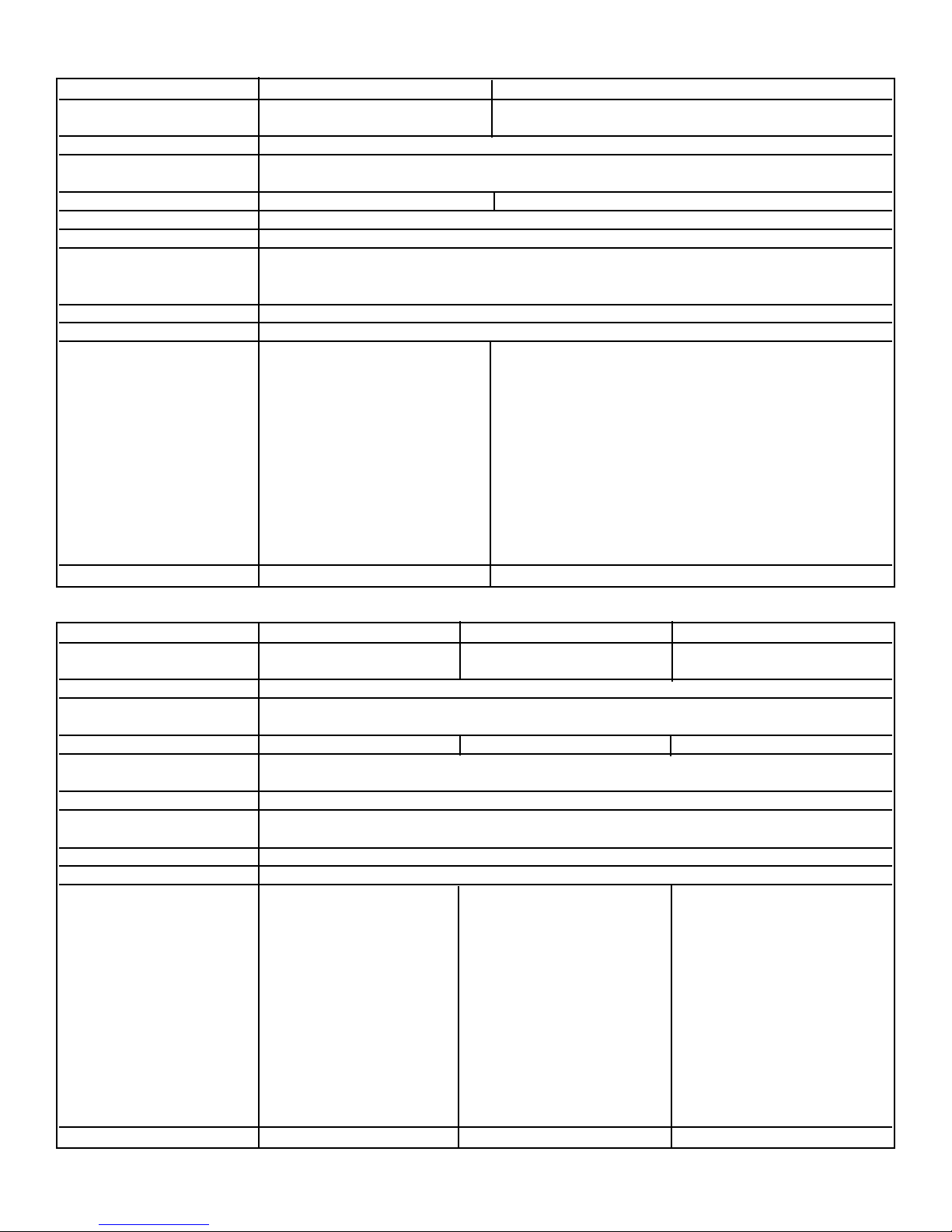
BASIC SPECIFICATIONS
DESCRIPTION VGSU103 (30” W.) VGSU163 (36” W.)
Cutout Width - Minimum 26 7/8” (68.3 cm) 34 3/8” (87.3 cm)
Maximum 29 7/8” (75.9 cm) 35 7/8” (91.1 cm)
Cutout Height - Minimum 2 1/2” (6.4 cm)
Cutout Depth - Minimum 18 5/8” (47.3 cm)
Maximum 20 1/8” (51.1cm)
Overall Width 30 3/4” (78.1 cm) 36 3/4” (93.3 cm)
Overall Height from Bottom 5” (12.7 cm)
Overall Depth from Rear 21” (53.3 cm)
Gas Requirements To field convert from natural or LP/Propane, the orifice spuds and regulator must be physically
changed. Order conversion kit NK2VGSU to convert to natural and LPK3VGSU to convert to LP.
Uses standard residential 1/2” (1.3 cm) I.D. gas service line.
Electrical Requirements 120 VAC/60 Hz; 4 ft. (121.9 cm), 3-wire cord with grounded 3-prong plug attached to product.
Maximum Amp Usage 2.0 amps
Surface Burner Rating
Left Front- 16,000 Nat./15,500 LP (BTU) 16,000 Nat./15,500 LP (BTU)
(4.8 Nat./4.65 LP [kw]) (4.8 Nat./4.65 LP [kw])
Left Rear- 12,000 Nat./11,500 LP (BTU) 12,000 Nat./11,500 LP (BTU)
(3.6 Nat./3.45 LP [kw]) (3.6 Nat./3.45 LP [kw])
Center Front/Rear N/A 12,000 Nat./11,500 LP (BTU)
(3.6 Nat./3.45 LP [kw])
Right Rear- 8,000 Nat./7,500 LP (BTU) 8,000 Nat./7,500 LP (BTU)
(2.4 Nat./2.25 LP [kw]) (2.4 Nat./2.25 LP [kw])
Right Front- 6,000 Nat./5,500 LP (BTU) 6,000 Nat./5,500 LP (BTU)
(1.8 Nat./1.65 LP [kw]) (1.8 Nat./1.65 LP [kw])
Approximate Shipping Weight 67 lb. (30.2 kg.) 80 lb. (36.0 kg)
DESCRIPTION DGCU105 (30” W.) DGCU165 (36” W.) DGCU155 (45” w.)
Cutout Width - Minimum 28 3/4” (73.0 cm) 34 1/2” (87.6 cm) 42 7/8” (108.9 cm)
Maximum 29 7/8” (75.9 cm) 35 7/8” (91.1 cm) 44 1/8” (112.1 cm)
Cutout Height - Minimum 2 3/4” (7.0 cm)
Cutout Depth - Minimum 19 11/16” (50.0 cm)
Maximum 20 1/2” (52.1cm)
Overall Width 30 3/4” (78.1 cm) 36 3/4” (93.3 cm) 45” (114.3 cm)
Overall Height from Bottom
(including connector) 4 1/4” (10.8 cm)
Overall Depth from Rear 21” (53.3 cm)
Gas Requirements Not field convertible - Must be ordered from factory either natural or LP/Propane. Uses
standard residential 1/2” (1.3 cm) I.D. gas service line.
Electrical Requirements 120 VAC/60 Hz; 4 ft. (121.9 cm), 3-wire cord with grounded 3-prong plug attached to product.
Maximum Amp Usage 2.0 amps
Surface Burner Rating
Left Front- 14,000 Nat./13,500 LP (BTU) 12,000 Nat./11,500 LP (BTU) 12,000 Nat./11,500 LP (BTU)
(4.1 Nat./4.0 LP [kw]) (3.5 Nat./2.8 LP [kw]) (3.5 Nat./2.8 LP [kw])
Left Rear- 12,000 Nat./11,500 LP (BTU) 10,000 Nat./LP (BTU) 8,000 Nat./LP (BTU)
(3.5 Nat./2.8 LP [kw]) (2.9 Nat./LP [kw]) (2.1 Nat./LP [kw])
Left Center N/A 14,000 Nat./13,500 LP (BTU) 10,000 Nat./LP (BTU)
(4.1 Nat./4.0 LP [kw]) (2.9 Nat./LP [kw])
Right Center N/A N/A 14,000 Nat./13,500 LP (BTU)
(4.1 Nat./4.0 LP [kw])
Right Rear- 8,000 Nat./LP (BTU) 8,000 Nat./LP (BTU) 6,000 Nat./LP (BTU)
(2.1 Nat./LP [kw]) (2.1 Nat./LP [kw]) (1.8 Nat./LP [kw])
Right Front- 6,000 Nat./LP (BTU) 6,000 Nat./LP (BTU) 8,000 Nat./LP (BTU)
(1.8 Nat./LP [kw]) (1.8 Nat./LP [kw]) (2.1 Nat./LP [kw])
Approximate Shipping Weight 67 lb. (30.2 kg.) 80 lb. (36.0 kg) 93 lb. (41.9 kg)
3

DESCRIPTION DGSU100 (30” W.) DGSU160 (36” W.)
Cutout Width - Minimum 29 1/8” (74.0 cm) 34 7/8” (88.6 cm)
Maximum 29 7/8” (75.9 cm) 35 7/8” (91.1 cm)
Cutout Height - Minimum 3 1/8” (7.9 cm)
Cutout Depth - Minimum 19 3/4” (50.2 cm)
Maximum 20 1/8” (51.1cm)
Overall Width 30 3/4” (78.1 cm) 36 3/4” (93.3 cm)
Overall Height from Bottom 4 3/8” (10.5 cm)
Overall Depth from Rear 21” (53.3 cm)
Gas Requirements To field convert from natural or LP/Propane, the orifice spuds and regulator must be physically
changed. Order conversion kit DLPK to convert to LP.
cm) I.D. gas service line.
Electrical Requirements 120 VAC/60 Hz; 4 ft. (121.9 cm), 3-wire cord with grounded 3-prong plug attached to product.
Maximum Amp Usage 2.0 amps
Surface Burner Rating
Left Front- 14,000 Nat./13,500 LP (BTU) 12,000 Nat./11,500 LP (BTU)
(4.1 Nat./4.0 LP [kw]) (3.5 Nat./2.8 LP [kw])
Left Rear- 12,000 Nat./11,500 LP (BTU) 10,000 Nat./LP (BTU)
(3.5 Nat./2.8 LP [kw]) (2.9 Nat./LP [kw])
Center Front/Rear N/A 14,000 Nat./13,500 LP (BTU)
Right Rear- 8,000 Nat./LP (BTU) 8,000 Nat./LP (BTU)
(2.1 Nat./LP [kw]) (2.1 Nat./LP [kw])
Right Front- 6,000 Nat./LP (BTU) 6,000 Nat./LP (BTU)
(1.8 Nat./LP [kw]) (1.8 Nat./LP [kw])
Approximate Shipping Weight 49 lb. (22.0 kg.) 74 lb. (33.3 kg)
Uses standard residential 1/2” (1.3
(4.1 Nat./4.0 LP [kw])
GENERAL INFORMATION
1. WARNING
Combustible items may ignite, metallic items may become hot and cause burns. If a cabinet storage is to be
provided the risk can be reduced by installing a rangehood that projects horizontally a minimum of 5” (12.7 cm)
beyond the bottom of the cabinets.
WARNING
2.
considerations.
3. All openings in the wall behind the appliance and in the floor under the appliance shall be sealed.
4. Keep appliance area clear and free from combustible materials, gasoline, and other flammable vapors.
5. Do not obstruct the flow of combustion and ventilation air.
6. Disconnect the electrical supply to the appliance before servicing.
7. When removing cooktop for cleaning and/or service;
A. Shut off gas at main supply
B. Disconnect AC power supply
C. Disconnect gas line to the inlet pipe.
D. Lift appliance out of cabinet cutout.
Electrical Requirement
8.
Normal grounded household current, 120 volts, 60 Hz, 15 amps, single phase. Electrical installation should
comply with national and local codes.
9. Air Supply and Ventilation
Means must be provided for any heavy-duty cooking appliance to exhaust combustion waste product to the
outside of the building. It is recommended that the cooktop be set under a powered, vented exhaust hood, or
non-vented recirculating hood. Nothing should obstruct the flow of combustion and ventilation air.
10. Gas Manifold Pressure
Natural gas - 5.0” W.C.P.
LP/Propane - 10.0” W.C.P.
11.
Flexible Connections
If the unit is to be installed with flexible couplings and/or quick disconnect fittings, the installer must use a
flexible connector of at least 1/2” I.D. (1.3 cm) NPT with suitable strain reliefs and comply with ANSI Z21.41
and Z21.69 standards.
:
The use of cabinets for storage above the appliance may result in a potential burn hazard.
:
This appliance shall not be used for space heating. This information is based on safety
4
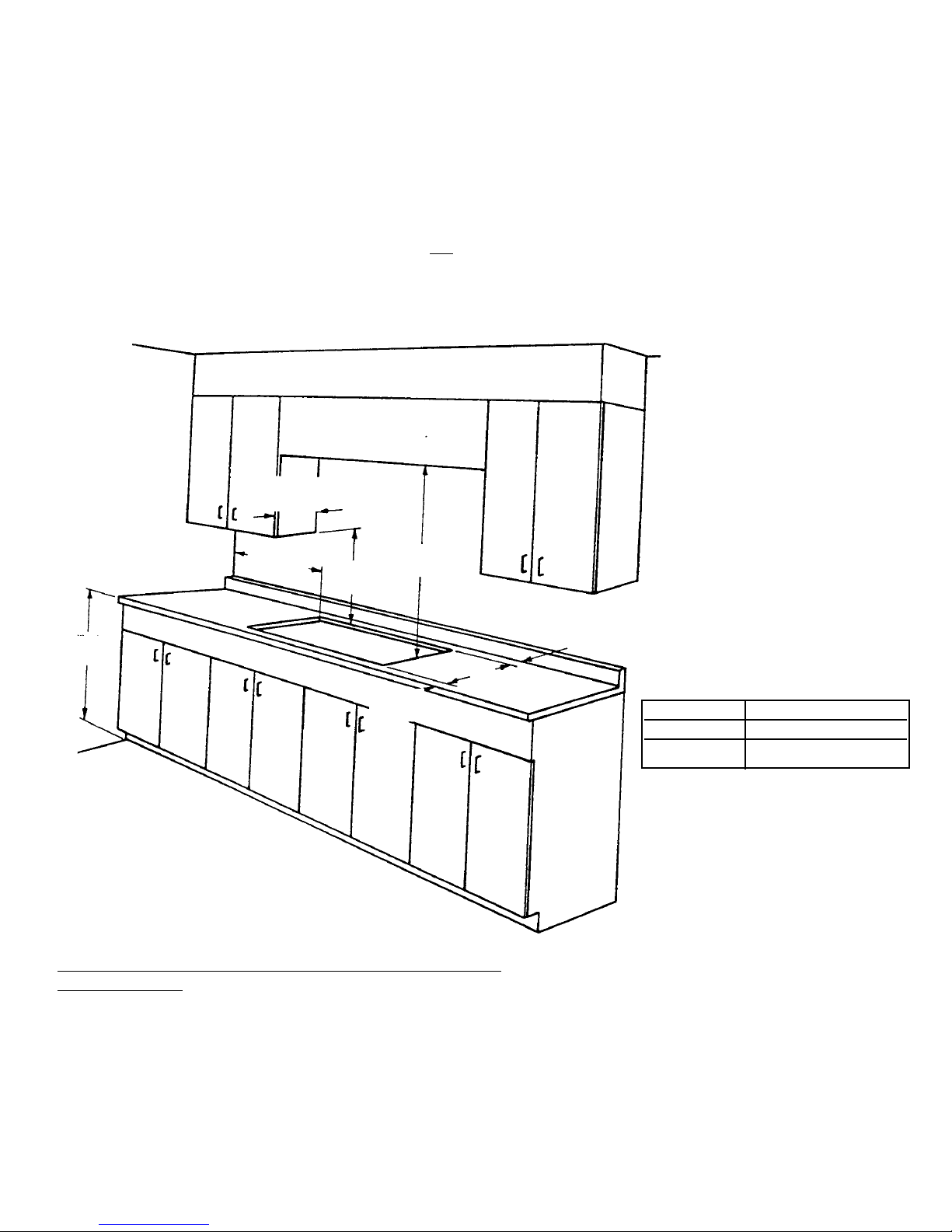
PROXIMITY TO SIDE CABINETS
1. The cooktop may be installed directly to existing base cabinets.
2. The cooktop CANNOT be installed directly adjacent to sidewalls, tall cabinets, tall appliances, or other side vertical
surfaces above 36” (91.4 cm) high. There must be a minimum of 8” (20.3 cm) side clearance from the cooktop to
such combustible surfaces above the 36” (91.4 cm) counter height.
3. Within the 8” (20.3 cm) side clearance to combustible vertical surfaces above 36” (91.4 cm), the maximum wall
cabinet depth must be 13” (33.0 cm) and wall cabinets within this 8” (20.3 cm) side clearance must be 18” (45.7 cm)
above the 36” (91.4 cm) high countertop.
4. Wall cabinet above the cooktop must be a minimum of 36” (91.4 cm) above the countertop for a full width of the
cooktop. This minimum height requirement does not
5. A 120 volt wall receptacle should be located approximately 6” (15.2 cm) below the countertop cutout and 12”
(30.5 cm) from the right side of the cutout.
13” max.
(33.0 cm)
apply if a rangehood is installed over the cooking surface.
36” min.
(91.4 cm)
3 1/8”
(7.9 cm)
36” min.
(91.4 cm)
8” min.
(20.3 cm)
18” min.
(45.7 cm)
MINIMUM CLEARANCES FROM ADJACENT COMBUSTIBLE
CONSTRUCTION
•Above countertop (above 36” [91.4 cm])
•Sides 8” (20.3 cm)
•Rear - See chart dimension “A”
•Within 8” (20.3 cm) side clearance. Wall cabinets no deeper
than 13” (33.0 cm)
•Must be minimum 18” (45.7 cm) above countertop
•Wall cabinets directly above the product must be minimum
36” (91.4 cm) above the countertop.
A
A
VGSU 3 1/2” (8.9 cm) min.
DGCU/DGSU 2 1/2” (6.4 cm) min.
5
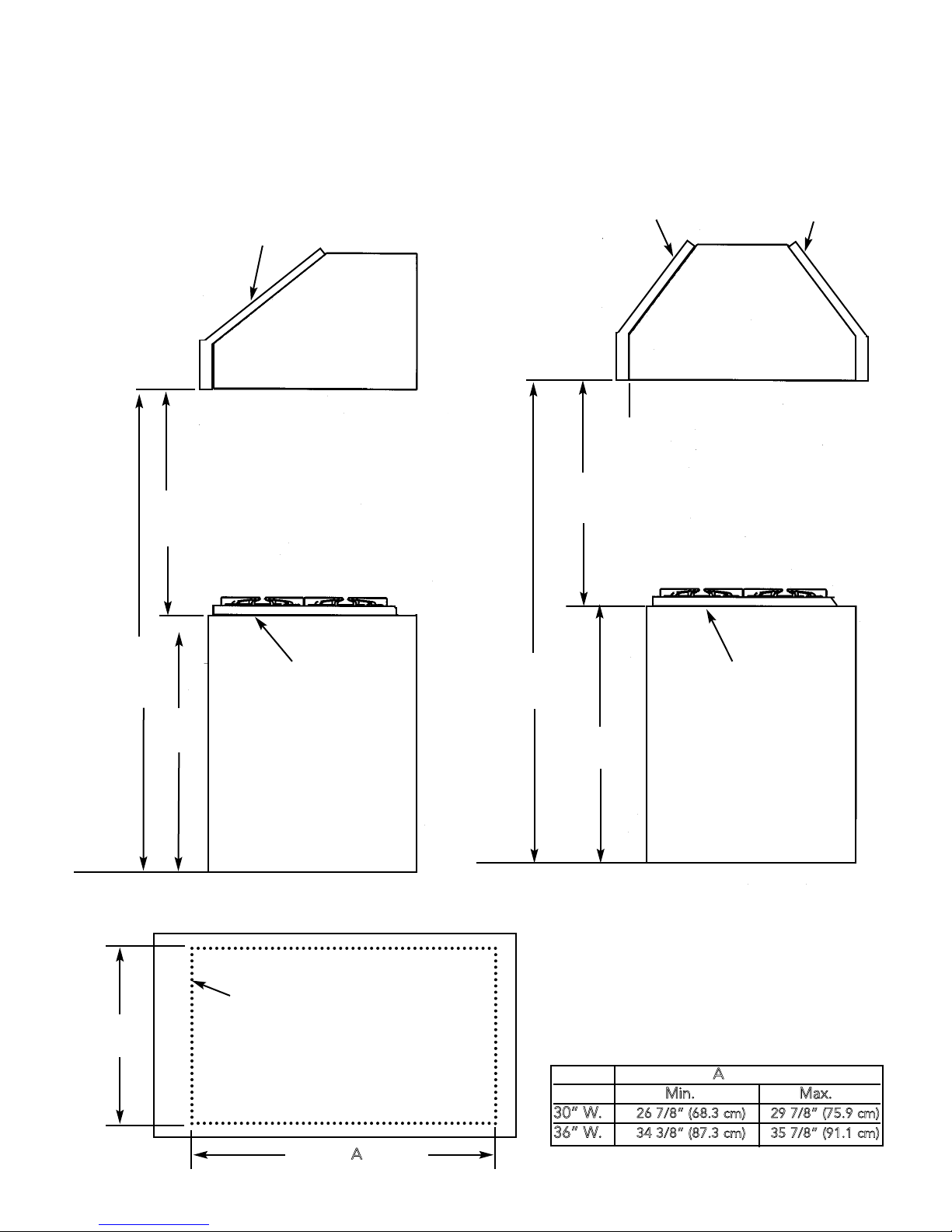
WOOD/COMPOSITE OVERLAY INSTALLATION
The bottom of the hood should be 30” (76.2 cm) min. to 36” (91.4 cm) above the countertop. This would
typically result in the bottom of the hood being 66” (167.6 cm) to 72” (182.9 cm) above the floor. Refer to the
rangehood installation instructions for further information. These dimensions provide for safe and efficient operation
of the hood.
WALL INSTALLATION
Wood/Composite Overlay
Metal Hood
30” (76.2 cm) min.
36” (91.4 cm) max
ISLAND INSTALLATION
Wood/Composite Overlay
Metal Hood
30” (76.2 cm) min.
36” (91.4 cm) max
66” - 72”
(167.6 cm -
182.9 cm)
36”
(92.4 cm)
Countertop
VGSU CUTOUT DIMENSIONS
Cutout
18 1/2”
(46.2 cm)
Opening
A
66” - 72”
(167.6 cm -
182.9 cm)
30” W.
36” W.
Countertop
36”
(92.4 cm)
A
Min. Max.
26 7/8” (68.3 cm) 29 7/8” (75.9 cm)
34 3/8” (87.3 cm) 35 7/8” (91.1 cm)
6
 Loading...