


Viking Designer DFUW152F, Designer DFUW142R, Designer DFUW142F, Designer DFUW152, Designer DUWC142 Installation Instructions Manual
...
USE/INSTALLATION
INSTRUCTIONS
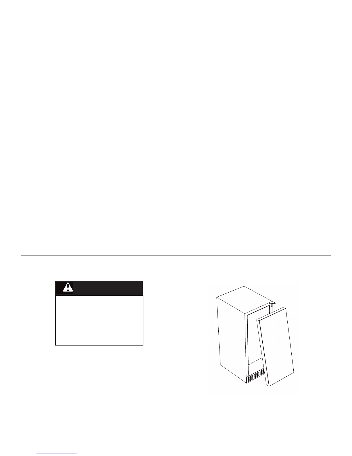
1155”” WW.. UUNNDDEERRCCOOUUNNTTEERR//FFRREEEESSTTAANNDDIINNGG WWIINNEE CCEELLLLAARR
RReettaaiinn ffoorr FFuuttuurree RReeffeerreennccee
IMPORTANT - PLEASE READ AND FOLLOW
••
Before beginning, please read these instructions completely and carefully.
• Do not remove permanently affixed labels, warnings, or plates from the product. This may void the warranty.
• Please observe all local and national codes and ordinances.
• Please ensure that this product is properly grounded.
• The installer should leave these instructions with the consumer who should retain for local inspector’s use and for
future reference.
WARNING
TToo rreedduuccee tthhee rriisskk ooff ffiirree,, eelleeccttrriiccaall sshhoocckk,, oorr iinnjjuurryy wwhheenn uussiinngg yyoouurr wwiinnee cceellllaarr,, ffoollllooww bbaassiicc pprreeccaauuttiioonnss iinncclluuddiinngg tthhe