

Viking VCSF036SS, VCSF036DSS, DDSF036DSS, DDSF036SS Service Book

SERVICE NOTEBOOK
Side-by-Side Refrigerators
Models
VCSF036SS
DDSF036SS
VCSF036DSS
DDSF036DSS
111 Front Street, Greenwood, Mississippi (MS) 38930 USA 662-455-1200
VIKING RANGE CORPORATION
Important Information
SAVE THESE INSTRUCTIONS
REVIEW ALL SERVICE INFORMATION IN THE APPROPRIATE SERVICE MANUAL AND TECHNICAL SHEETS
BEFORE BEGINNING REPAIRS.
Pride and workmanship go into every product to provide our customers with quality products. It is possible, however,
that during its lifetime, a product may require service. Products should be serviced only by a qualified service
technician that is familiar with the safety procedures required in the repair and who is equipped with the proper tools,
parts, testing instruments, and the appropriate service manual.
Safety Information
We have provided many important safety messages in
this manual and on the appliance. Always read and
obey all safety messages. This is the safety alert
symbol.
All safety messages will identify the hazard, tell you how
to reduce the chance of injury, and tell you what can
happen if the instructions are not followed.
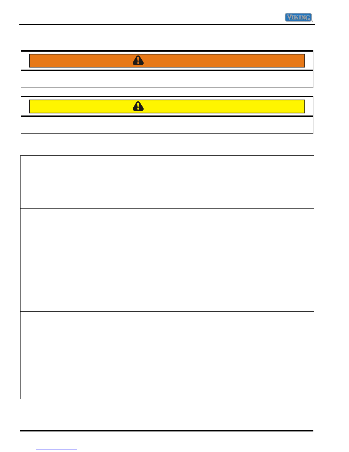
This symbol alerts you to hazards that can kill or hurt
you and others. All safety messages will be preceded
by the safety alert symbol and the word “DANGER”,
“WARNING” or “CAUTION”. These words mean:
DANGER
IMMEDIATE HAZARDS WHICH WILL RESULT IN
SEVERE PERSONAL INJURY OR DEATH.
WARNING
Hazards or unsafe practices which COULD result in
severe personal injury or death.
CAUTION
Hazards or unsafe practices which COULD result in
minor personal injury or product or property
damage.
WARNING
To avoid risk of serious injury or death, repairs
should not be attempted by unauthorized personnel
CAUTION
VIKING will not be responsible for any injury or
property damage from improper service procedures.
If performing service on your own product, you
must assume responsibility for any personal injury
or property damage which may result
To locate an authorized servicer, call:
Viking Customer Service
Phone No. 1-888-845-4641
Address your written correspondence to:
Viking Preferred Service
1803 HWY 82 West
Greenwood, MS 38930
.
.
2 ©2007 Viking Preferred Service
Important Information
Freestanding Side-By-Side
Refrigerator/Freezer Warranty
TWO YEAR FULL WARRANTY
Freestanding refrigerators/freezers and all of their components and accessories, except as detailed below*, are warranted to be free from
defects in material or workmanship under normal household use for a period of two (2) years from the date of original retail purchase. Viking
Range Corporation, warrantor, agrees to repair or replace, at its option, any part which fails or is found to be defective during the warranty
period *Painted and decorative items are warranted to free from defective materials or workmanship for a period of ninety (90) days from the
date of original retail purchase. ANY DEFECTS MUST BE REPORTED TO THE SELLING DEALER WITHIN NINETY (90) DAYS FROM
DATE OF ORIGINAL RETAIL PURCHASE.
SIX YEAR FULL WARRANTY
Any sealed refrigeration system component, as listed below, or any automatic ice maker is warranted to be free from defective materials or
workmanship in normal household use during the third through the sixth year from the date of original retail purchase. Viking Range
Corporation, warrantor, agrees to repair or replace, at its option, any part which fails or is found to be defective during the warranty period.
Sealed Refrigeration System Components:
Compressor, Evaporator, Condenser, Connecting Tubing, Dryer/Strainer
Any sealed refrigeration system component, as listed above, which fails due to defective materials or workmanship in normal household use
TWELVE YEAR LIMITED WARRANTY
during the seventh through the twelfth year from the date of original retail purchase will be repaired or replaced, free of charge for the part
itself, with the owner paying all other costs, including labor.
NINETY (90) DAY RESIDENTIAL PLUS WARRANTY This warranty applies to applications where use of the product extends beyond
normal residential use. Examples are, but not limited to, bed and breakfasts, fire stations, private clubs, churches, etc. This warranty
excludes all commercial locations such as restaurants, food service locations and institutional food service locations.
This warranty extends to the original purchaser of the product warranted hereunder and to each transferee owner of the product during the
term of the warranty.
This warranty shall apply to products purchased and located in the United States and Canada. Products must be purchased in the country
where service is requested. Warranty labor shall be performed by an authorized Viking Range Corporation service agency or representative.
Warranty shall not apply to damage resulting from abuse, accident, natural disaster, loss of electrical power to the product for any reason,
alteration, improper installation, improper operation or repair or service to the product by anyone other than an authorized Viking Range
Corporation service agency or representative. Warranty shall not apply to damage resulting from indoor units being used in outdoor
situations. This warranty does not apply to commercial usage
Warrantor is not responsible for consequential or incidental damage whether arising out of breach of warranty, breach of contract, or
otherwise. Some jurisdictions do not allow the exclusion or limitation of incidental or consequential damages, so the above limitation or
exclusion may not apply to you.
Owner shall be responsible for proper installation, providing normal care and maintenance, providing proof of purchase upon request, and
making the appliance reasonably accessible for service. If the product or one of its component parts contains a defect or malfunction during
the warranty period, after a reasonable number of attempts by the warrantor to remedy the defects or malfunctions, the owner is entitled to
either a refund or replacement of the product or its component part or parts. Replacement of a component part includes its free installation.
Warrantor’s liability on any claim of any kind, with respect to the goods or services covered hereunder, shall in no case exceed the price of
the goods or service or part there of which gives rise to the claim.
WARRANTY SERVICE: Under the terms of this warranty, service must be performed by a factory authorized Viking Range Corporation
service agent or representative. Service will be provided during normal business hours, and labor performed at overtime or premium rates
shall not be covered by this warranty. To obtain warranty service, contact the dealer from whom the product was purchased, an authorized
Viking Range Corporation service agent, or Viking Range Corporation. Provide model and serial number and date of original purchase. For
the name of your nearest authorized Viking Range Corporation service agency, call the dealer from whom the product was purchased or
Viking Range Corporation. IMPORTANT: Retain proof of original purchase to establish warranty period.
The return of the Owner Registration Card is not a condition of warranty coverage. You, however, should return the Owner
Registration Card so that Viking Range Corporation can contact you should any question of safety arise which could affect
you.
. This warranty does not cover any food or medicine loss due to product failure.
Any implied warranties of merchantability and fitness applicable to the above described refrigerator are limited in duration to
the period of coverage of the applicable express written limited warranties set forth above. Some jurisdictions do not allow
limitations on how long an implied warranty lasts, so the above limitation may not apply to you. This warranty gives you
specific rights, and you may also have other rights which may vary from jurisdiction to jurisdiction.
Specifications are subject to change without notice.
For more product information, call 1-888-VIKING1 (845-4641), or visit our web
©2007 Viking Preferred Service 3
http://www.vikingrange.com
site at
Table of Contents
Important Information ......................................................2
Safety Information ...................................................2
General Information ........................................................6
Fully Electronic Defrost System .............................. 6
Serial Number Location...........................................6
Installation ...............................................................6
Location.............................................................. 6
Measuring the Opening...................................... 6
Leveling ................................................................... 6
Leveling doors....................................................6
Operation.................................................................7
Climate Controls.................................................7
Initial Temperature Setting................................. 7
Adjusting the Control.......................................... 7
Temperature Control Guide ...............................7
Max Ice............................................................... 7
Water Filter Indicator..........................................7
Vacation Mode ................................................... 7
Door Open Alarm ...............................................7
High Temp Alarm ............................................... 8
Max Cold ............................................................8
User Preferences ............................................... 8
Temperature Display “F_C”................................8
Alarm “AL” ..........................................................8
Auto Light Level Selection “LL”
(select models)
Sabbath Mode “SAB” ......................................... 8
Warm Cabinet Surfaces.....................................8
Dispenser Control Panel .........................................9
Dispenser Light ..................................................9
Dispenser Pad....................................................9
Removable Tray.................................................9
Water and Ice Dispenser....................................9
Dispenser Lock ..................................................9
Auto Light ...........................................................9
Light....................................................................9
Sabbath Mode....................................................9
Care and Cleaning ................................................ 10
Refrigerator Cleaning Chart .............................10
Operating Sounds ................................................. 11
Troubleshooting Chart................................................... 12
Dispenser Troubleshooting Chart ......................... 18
Seconds to dispense 10 oz. water ...................22
Control Board ................................................................23
Programming Mode...............................................23
Defrost Operation.................................................. 23
Forced Defrost Mode ............................................23
Service Test Mode ................................................ 23
...................................................8
Fahrenheit or Celsius Mode.................................. 25
Show Room Mode ................................................ 25
Sabbath Mode ...................................................... 25
Alarm Enable Mode .............................................. 25
Light Level Mode (Select Models) ........................ 25
Component Testing ...................................................... 26
System Diagnosis ......................................................... 32
Symptoms of an Overcharge................................ 32
Symptoms of Air in System................................... 32
Symptoms of Refrigeration Shortage ................... 33
Symptoms of Low or High Ambient Temperature
Installation............................................................. 33
Heat Load ........................................................ 33
Symptoms of a Restriction.................................... 34
Service Procedure ........................................................ 35
Service Equipment................................................ 35
Leak Testing ......................................................... 35
Testing Systems Containing a Refrigerant
Charge ............................................................. 35
Testing Systems Containing No Refrigerant
Charge ............................................................. 35
Refrigerant Precautions........................................ 36
Line Piercing Valves ............................................. 36
Open Lines ........................................................... 36
Compressor Operational Test .............................. 36
Dehydrating Sealed Refrigeration System ........... 37
Restrictions ........................................................... 37
Symptoms........................................................ 37
Testing for Restrictions.................................... 37
Evacuation and Charging ..................................... 38
Evacuation ....................................................... 38
Charging .......................................................... 39
Refrigerant Charge ............................................... 39
HFC134a Service Information .............................. 39
Health, Safety, and Handling........................... 39
Comparison of CFC12 and HFC134a
Properties
Brazing.................................................................. 40
Replacement Service Compressor....................... 41
Compressor Testing Procedures..................... 41
Drier Replacement................................................ 41
Refrigerant Flow ................................................... 42
Cabinet Air Flow ................................................... 43
Water and Ice Dispenser ...................................... 44
Disassembly Procedures .............................................. 45
Upper Refrigerator Section Light Bulb Removal .. 45
Crisper Section Light Bulb Removal..................... 45
Light Switch Removal ........................................... 45
Electronic Control Removal .................................. 45
........................................................ 40
4 ©2007 Viking Preferred Service
Table of Contents
Electronically Controlled Damper Removal .......... 46
Refrigerator Thermistor Removal.......................... 46
Crisper Light Cover and Socket Removal............. 46
Water Filter Removal ............................................ 47
Initial Installation...............................................47
Replacing Water Filter .....................................47
Access to Machine Compartment .........................47
Water Filter Assembly Removal............................ 47
Water Tank Assembly Removal............................ 48
Water Valve Removal ........................................... 48
Upper Freezer Section Light Bulb Removal .........49
Auger Motor Assembly Removal ..........................49
Upper Freezer Light Socket Removal................... 49
Auger Motor Capacitor Removal...........................49
Lower Freezer Section Light Bulb Removal .........49
Auger Motor Removal ........................................... 50
Evaporator Fan Motor Assembly ..........................50
Evaporator Fan Motor and Fan Blade...................50
Defrost Thermostat Removal ................................ 50
Defrost Heater Removal .......................................51
Evaporator Removal .............................................51
Ice Maker Removal ............................................... 51
Freezer Thermistor Removal ................................ 52
Condensate Drain Tube ....................................... 52
Overload/Relay Removal...................................... 52
Compressor Removal........................................... 52
Condenser Fan Motor and Blade Removal.......... 53
Condensate Drip Pan Removal............................ 53
Condenser Removal............................................. 53
Front and Rear Leveling Rollers Removal ........... 54
Door Gasket Removal .......................................... 54
Dispenser Light Bulb Removal ............................. 54
Dispenser Façade Removal ................................. 54
Dispenser Light Socket......................................... 54
Dispenser Pad and Switch Removal .................... 55
Dispenser Board Removal.................................... 55
Dispenser Ice Chute Door and Solenoid
Removal
Dispenser Water Tube Removal .......................... 56
Door and Hinge Removal ..................................... 56
Door Handle Removal .......................................... 57
Door Handle Installation ....................................... 57
Appendix A ................................................................... 58
................................................................ 55
©2007 Viking Preferred Service 5
General Information
Fully Electronic Defrost System
The Control Board adapts the compressor run time
between defrosts to achieve optimum defrost intervals
by monitoring the length of time the defrost heater is on.
After initial power up, defrost interval is 4 hours
compressor run time. Defrost occurs immediately after
the 4 hours. Once unit is ready to defrost there is a 4
minute wait time prior to the beginning of the defrost
cycle.
Serial Number Location
The model number and serial number are located on the
data plate. The data plate is located in the refrigerator
compartment on the upper left side.
Installation
Location
Do not install refrigerator near oven, radiator or other
heat source. If this is not possible, shield the refrigerator
with cabinet material.
Do not install where temperature falls below 55° F or
rises above 110° F. Malfunction may occur at this
temperature.
Refrigerator is designed for indoor household application
only.
Leveling
CAUTION
Use care when leveling the refrigerator to avoid
damaging the floor or refrigerator.
To enhance the appearance and maintain performance,
the refrigerator should be level.
NOTE: Complete any required door reversal, panel
installation and/or a water supply connection,
before leveling.
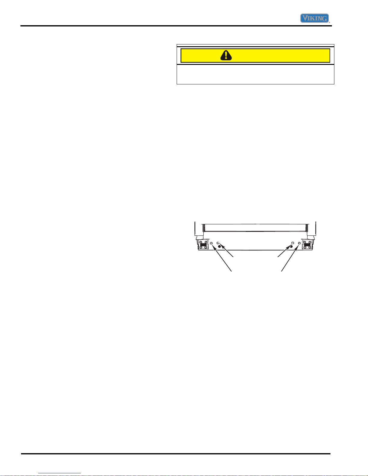
1. Remove the toe grille.
2. Turn the front adjustment screws clockwise to raise
and counterclockwise to lower the front of the
refrigerator.
3. Turn the rear adjustment screws clockwise to raise
and counterclockwise to lower the rear of the
refrigerator.
4. Using a level, make sure front of refrigerator is ¼” or
½ bubble higher than back of refrigerator and that the
refrigerator is level from side to side.
5. If required, correct rocking of refrigerator by turning
rear adjustment screw clockwise to raise rocking
corner.
Measuring the Opening
When installing your refrigerator, allow ½” space at top
and ½” space behind machine compartment cover
(located in the rear) for proper air circulation. If the
refrigerator is placed with the door hinge side against a
wall, you may want to allow additional space so the door
can be opened wider.
Subflooring or floor coverings (i.e. carpet, tile, wood
floors, rugs) may make your opening smaller than
anticipated.
Some clearance may be gained by using the leveling
procedure under Leveling.
IMPORTANT: If refrigerator is to be installed into a
recess where the top of the refrigerator
is completely covered, use dimensions
from floor to top of hinge cap to verify
proper clearance.
Rear Adjustment Screws
Front Adjustment Screws
Leveling doors
1. Turn front adjustment screw clockwise to raise front
corner of door.
2. If one refrigerator door has reached the limit of its
adjustment range and doors are still not level, raise
or lower the opposite door by turning roller
adjustment screw counterclockwise.
3. Check with level to verify ¼” tilt to the back for proper
door closure.
4. If refrigerator is aligned and stable, replace toe grille.
6 ©2007 Viking Preferred Service
General Information
Operation
MAX
ICE
ORDER REPLACE
WATER
FILTER
INDICATOR
HOLD 3 SECONDS
TO RESET
VACATION
MODE
FREEZER
UP
DOWN
TEMP
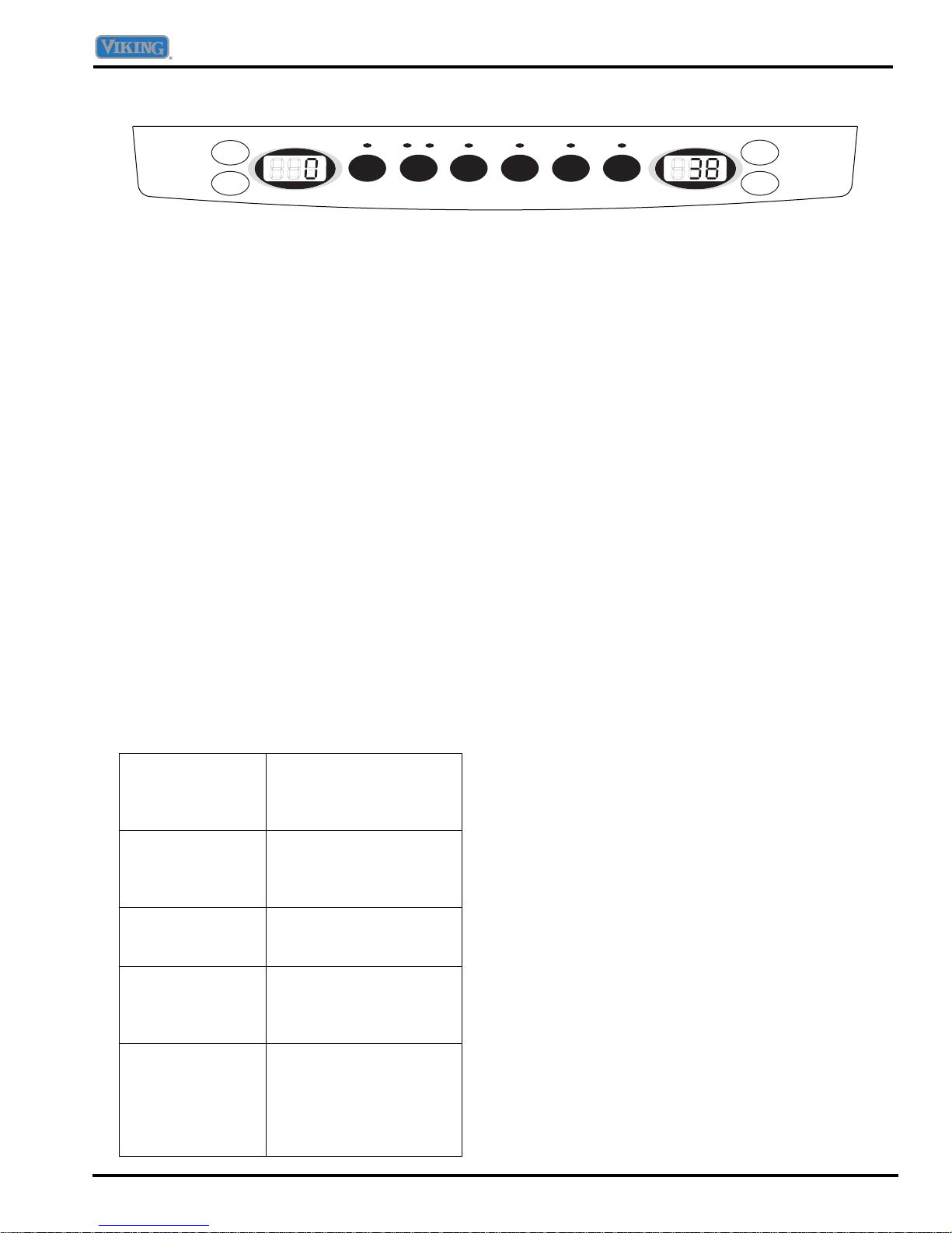
Climate Controls
The control panel is located at the top front of the
refrigerator compartment.
Initial Temperature Setting
Temperatures are preset at the factory at 38° F in the
refrigerator compartment and 0° F in the freezer
compartment.
Adjusting the Control
24 hours after adding food, you may decide that one or
both compartments should be colder or warmer. If so,
adjust the control as indicated in the Temperature
Control Guide below.
The first touch of the UP or DOWN buttons shows the
current temperature setting.
The display will show the new setting for approximately
three seconds, and then return to the actual temperature
currently within that compartment.
Do not change the temperature in either compartment
more than one degree at a time. Allow temperature to
stabilize for 24 hours before making a new temperature
adjustment.
Temperature Control Guide
Refrigerator too
cold
Set the refrigerator
control to next higher
number by pressing the
UP button.
Refrigerator too
warm
Set the refrigerator
control to next lower
number by pressing the
DOWN button.
Freezer too cold Set the freezer control to
next higher number by
pressing the UP button.
Freezer too warm Set the freezer control to
next lower number by
pressing the DOWN
button.
Turn refrigerator
off
Press the FREEZER
TEMP UP button until
“OFF” appears in the
display. Press the
FREEZER TEMP DOWN
button to turn back on.
HIGH
TEMP
ALARM
DOOR
OPEN
ALARM
MAX
COLD
REFRIGERATOR
TEMP
UP
DOWN
Max Ice
When activated, Max Ice reduces the freezer
temperature to the optimum setting for 24 hours in order
to produce more ice.
NOTE: When the Max Ice feature is in operation, the
UP and DOWN buttons for the freezer control
will not operate.
Water Filter Indicator
When a water filter is installed in the refrigerator, the
yellow ORDER light will illuminate when:
• 90 percent of the volume of water has passed
through the filter
• 11 months have elapsed since the filter was installed.
The red REPLACE light will illuminate when:
• the rated volume of water has passed through the
filter
• 12 months have elapsed since the filter was installed.
A new filter should be installed immediately when the
REPLACE light is illuminated.
After replacing the filter, press and hold the WATER
FILTER INDICATOR button for three seconds. The
ORDER and REPLACE lights will go off.
Vacation Mode
The Vacation Mode feature causes the freezer to defrost
less frequently, conserving energy. The VACATION
MODE indicator light will illuminate when the feature is
activated. To deactivate, press the VACATION MODE
button again OR open either door. The indicator light will
go off.
NOTE: Door openings will not deactivate Vacation
Mode for approximately one hour after activation.
Door Open Alarm
The Door Open Alarm will alert you when one of the
doors has been left open for five continuous minutes.
When this happens, an audible alarm will sound every
few seconds until the door is closed OR the DOOR
OPEN ALARM button is pressed to deactivate the
feature.
©2007 Viking Preferred Service 7

General Information
High Temp Alarm
The High Temp Alarm system will alert you if the freezer
or refrigerator temperatures exceed normal operating
temperatures due to a power outage or other event.
When activated, the HIGH TEMP ALARM light will
illuminate.
If the freezer or refrigerator temperatures have
exceeded these limits, the display will alternately show
the current compartment temperatures and the highest
compartment temperatures reached when the power
was out. An audible alarm will sound repeatedly.
Press the HIGH TEMP ALARM button once to stop the
audible alarm. The HIGH TEMP ALARM light will
continue to flash and the temperatures will alternate until
the temperatures have stabilized.
To turn off HIGH TEMP ALARM, press and hold the
HIGH TEMP ALARM button for three seconds. The
indicator light will go off.
Max Cold
When activated, Max Cold causes the refrigerator and
freezer temperatures to drop to the minimum settings on
the control. This cools down the refrigerator and freezer
after extended door openings or when loading the
refrigerator or freezer with warm food.
NOTE: When the Max Cold feature is in operation, the
UP and DOWN buttons for the refrigerator and
freezer controls will not operate.
To activate, press the MAX COLD button. MAX COLD
will deactivate automatically after 12 hours, OR press
the MAX COLD button to deactivate the feature.
User Preferences
Access the User Preferences menu to:
• Change the temperature display from °F to °C
• Enable or disable audible alarms.
• Adjust the light level at which the Dispenser Auto
Light will illuminate (when this feature is activated on
the ice and water dispenser) (select models)
• Activate the Sabbath Mode
To access the User Preferences menu:
1. Press and hold the DOOR OPEN ALARM button for
three seconds.
3. When the desired feature is displayed, use the
REFRIGERATOR TEMP UP and DOWN buttons to
change the status.
4. When changes are complete, press THE DOOR
OPEN ALARM button for three seconds OR close the
door.
Temperature Display “F_C”
Change the display to show temperatures in degrees
Fahrenheit or degrees Celsius.
Alarm “AL”
When the Alarm mode is “OFF”, all audible alarms will
be disabled until the feature is turned on.
Auto Light Level Selection “LL” (select models)
This setting adjusts the light level at which the dispenser
light will illuminate. Setting “1” is the darkest light level
setting, setting “9” is the lightest light level setting. The
AUTO LIGHT (select models) must be activated on the
ice and water dispenser control to take advantage of this
option.
Sabbath Mode “SAB”
When the Sabbath Mode is “On”, all control lights and
the night light will be disabled until the feature is turned
“OFF”. This feature does not disable the interior lights.
Press any pad to restore the control lights.
Warm Cabinet Surfaces
At times, the front of the refrigerator cabinet may be
warm to the touch. This is a normal occurrence that
helps prevent moisture from condensing on the cabinet.
This condition will be more noticeable when the
refrigerator is first started, during hot weather and after
excessive or lengthy door openings.
NOTE: When in the User Preferences mode, a short
title for the feature will appear in the FREEZER
TEMP display and the feature status will appear
in the REFRIGERATOR TEMP display.
2. Use the FREEZER TEMP UP and DOWN buttons
to scroll through the features.
8 ©2007 Viking Preferred Service
General Information
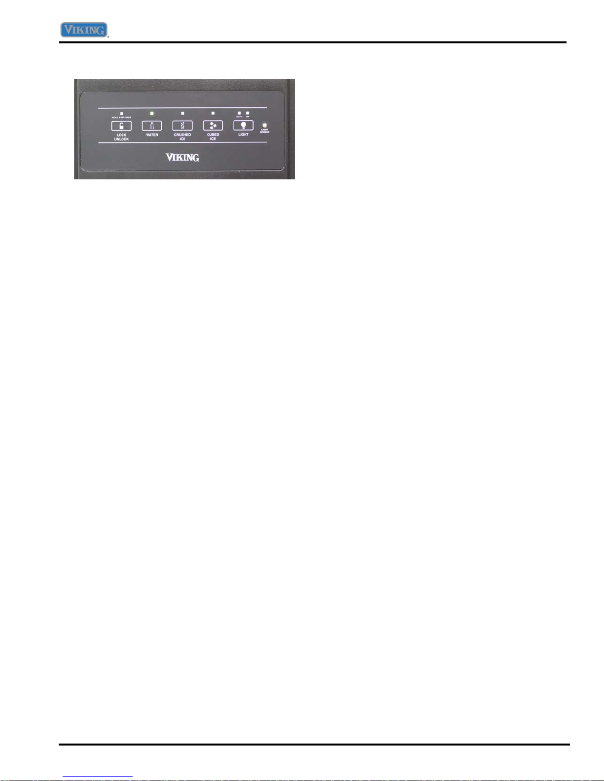
Dispenser Control Panel
Dispenser Light
A light activates within the dispenser area at full power
when dispensing ice or water with the dispenser pad.
Dispenser Pad
The Dispenser Pad is located on the back wall of the
dispensing area. When the dispenser pad is pressed,
the selection chosen on the dispenser control panel will
dispense.
Removable Tray
The Removable Tray at the bottom of the dispenser area
is designed to collect small spills and may be easily
removed for cleaning and emptying purposes.
Auto Light
The Auto Light function activates the dispenser light at
half-power when the light sensor detects that the light
levels in room are low.
To Activate Auto Light:
• Press LIGHT button. A green indicator light above
AUTO illuminates when the sensor is active.
To Deactivate Auto Light:
• Press LIGHT button. The green indicator light will go
out.
NOTE: The dispenser light will operate when Auto Light
is ON or OFF.
Light
To Activate Light:
• Press the LIGHT button again to turn the dispenser
light on continuously. The ON indicator light will
illuminate.
To Deactivate Light:
• Press the LIGHT button again to turn the dispenser
light off.
Sabbath Mode
IMPORTANT: Removable tray does not drain. Do not
allow tray to overflow. If it does, remove
tray and wipe up overflow.
Water and Ice Dispenser
To Use Dispenser Pad:
• Select WATER, CRUSHED ICE, or CUBED ICE
mode by pushing button on dispenser control panel.
A green light above button indicates mode selection.
• Press against dispenser pad.
• Release pressure on dispenser pad to stop
dispensing.
• If dispenser is active for more than five minutes, an
automatic lock out sensor will shut down power to
dispenser area.
Dispenser Lock
The Dispenser Lock prevents ice or water from being
dispensed.
To Lock Dispenser:
• Press and hold the LOCK/UNLOCK button for three
seconds. A green indicator light above button will
illuminate when the dispenser is locked.
To Unlock Dispenser:
• Hold the LOCK/UNLOCK button for three seconds.
The green indicator light above button will go out.
When activated, the Sabbath Mode deactivates the
control lights while leaving the control operational.
To Activate Sabbath Mode:
• Press and hold the LOCK/UNLOCK and LIGHT
buttons simultaneously for three to four seconds.
After three to four seconds, the dispenser lights will
turn off.
To Deactivate Sabbath Mode:
• Press and hold both the LOCK/UNLOCK and LIGHT
buttons simultaneously for three to four seconds.
After three to four seconds, the dispenser lights will
activate.
NOTE: Dispenser light will not activate during
dispensing while in this mode.
NOTE: If the power fails, the control will remain in
Sabbath Mode when power returns.
©2007 Viking Preferred Service 9
General Information
Care and Cleaning
WARNING
To avoid risk of electrical shock which can cause severe personal injury or death, disconnect power to
unit before cleaning.
CAUTION
Only use recommended cleaning products. Do not place buckets, shelves, or accessories in a dishwasher.
Cracking or warping may result.
Refrigerator Cleaning Chart
PART DO NOT USE DO
Cabinet Interior Abrasive or harsh cleaners
Ammonia
Chlorine bleach
Concentrated detergents or solvents
Metal or plastic-textured scouring pads
Stainless Steel Doors and
Exterior
IMPORTANT:
Damage to stainless steel
finish due to improper use of
cleaning products or nonrecommended products is not
covered under this product’s
warranty.
Door Gaskets Abrasive or harsh cleaners
Condenser Coil
Remove base grille to access.
Condenser Fan Outlet Grille
See back of refrigerator.
Accessories
Shelves, buckets,
drawers, etc.
Abrasive or harsh cleaners
Ammonia
Chlorine bleach
Concentrated detergents or solvents
Metal or plastic-textured scouring pads
Vinegar-based products
Citrus-based cleaners
Metal or plastic-textured scouring pads
Use a vacuum cleaner hose nozzle.
Use a vacuum cleaner hose nozzle
A dishwasher Follow removal and installation
Use 4 tablespoons of baking soda
dissolved in 1 quart warm soapy
water.
Rinse surfaces with clean warm
water and dry immediately to avoid
water spots.
Use warm, soapy water and a soft,
clean cloth or sponge.
Rinse surfaces with clean warm
water and dry immediately to avoid
water spots.
To polish and help prevent
fingerprints, follow with Stainless
Steel Magic Spray.
Use warm, soapy water and a soft,
clean cloth or sponge.
with brush attachment.
instructions from appropriate feature
section.
Allow accessories to adjust to room
temperature.
Dilute mild detergent and use a soft
clean cloth or sponge for cleaning.
Use a plastic bristle brush to get into
crevices.
Rinse surfaces with clean warm
water.
Dry glass and clear items
immediately to avoid spots.
10 ©2007 Viking Preferred Service
General Information
Operating Sounds
Improvements in refrigeration design may produce sounds in your new refrigerator that are different or were not
present in an older model. These improvements were made to create a refrigerator that is better at preserving food,
is more energy efficient, and is quieter overall. Because new units run quieter, sounds may be detected that were
present in older units, but were masked by higher sound levels. Many of these sounds are normal. Please note that
the surfaces adjacent to a refrigerator, such as hard walls, floors and cabinetry may make these sounds seem even
louder. The following are some of the normal sounds that may be noticed in a new refrigerator.
SOUND POSSIBLE CAUSE SOLUTION
Freezer control clicks when starting or stopping
compressor.
Defrost timer or electric damper control sounds like an
electric clock and snaps in and out of defrost cycle.
Air rushing or
whirring
Condenser fan makes this noise while operating. Normal operation
Freezer fan makes this noise while operating. Normal operation
Freezer fan slows to a stop as the freezer door is opened. Normal operation
Gurgling or
boiling sound
Evaporator and heat exchanger refrigerant make this noise
when flowing.
Ice cubes from ice maker drop into ice bucket. Normal operation Thumping
Dispenser ice chute closing. Normal operation
Compressor makes a pulsating sound while running. Normal operation Vibrating noise
Refrigerator is not level. See Leveling.
Buzzing Ice maker water valve hookup buzzes when ice maker fills
with water.
Humming
Ice maker is in the ON position without water connection. Stop sound by raising ice maker
Ice auger hums as auger agitates ice during dispensing. Normal operation
Compressor can make a high pitched hum while operating. Normal operation
Solenoid valve operating ice chute door. Normal operation
Normal operation Clicking
Normal operation
Normal operation
Normal operation
arm to OFF position.
©2007 Viking Preferred Service 11
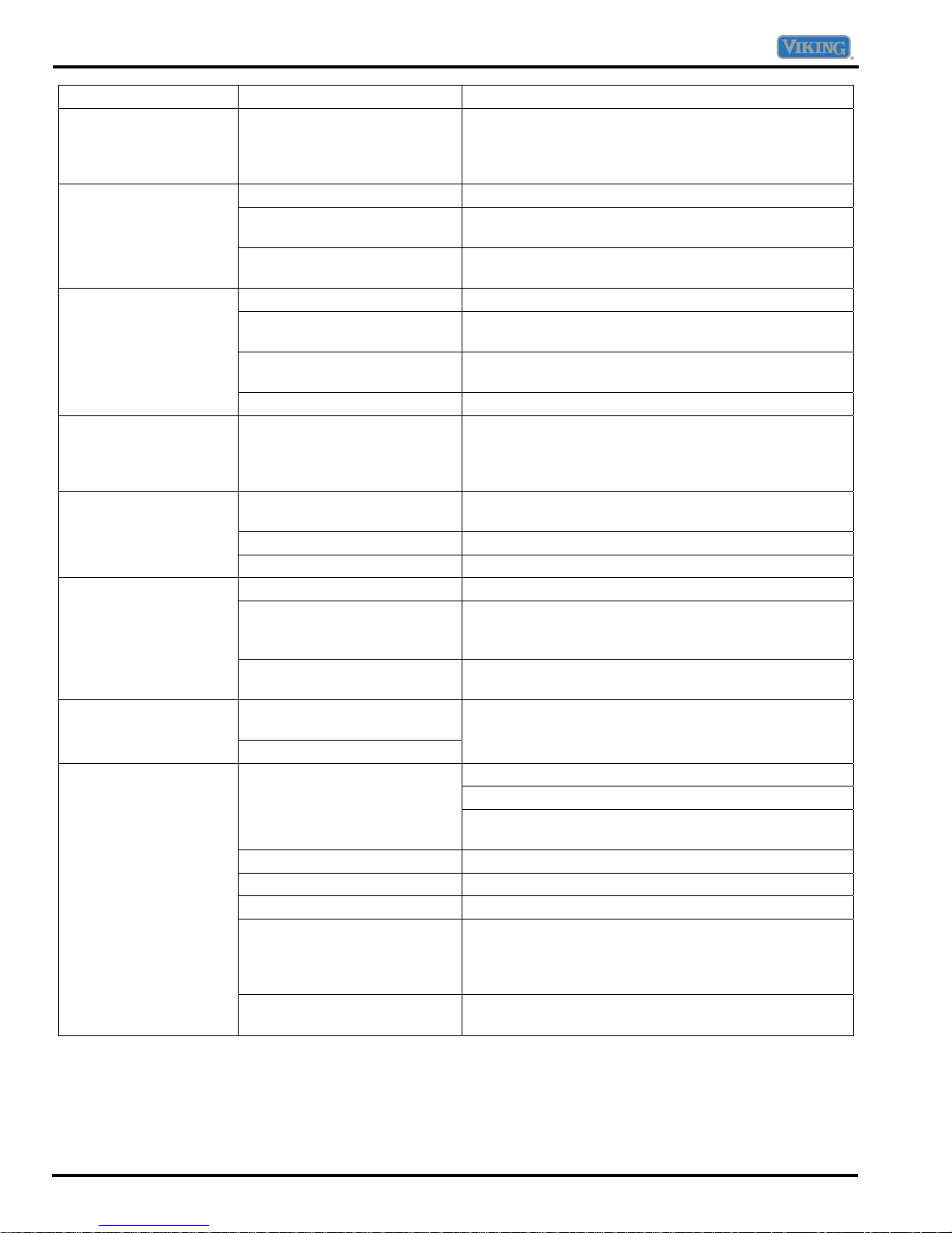
Troubleshooting Chart
Symptom Possible Cause Corrective Action
Freezer control and
lights are on, but
compressor is not
operating
Temperature-controlled
drawers are too warm
Refrigerator does not
operate
Refrigerator still won’t
operate
Water droplets form on
outside of refrigerator
Food temperature is
too cold
Refrigerator has an
odor
Food temperature is
too warm
Unit is in defrost mode. Normal operation. Wait 40 minutes to see if
compressor restarts.
Control settings are too low. Adjust controls.
Freezer controls are set too
low.
Drawer is improperly
positioned.
Refrigerator is not plugged in. Plug in refrigerator.
Touch temperature controls
are set to “–”.
Fuse is blown, or circuit
breaker needs to be reset.
Power outage has occurred. Call local power company to report outage.
Unit is malfunctioning. Unplug refrigerator and transfer food to another
Door gaskets are not sealing
properly.
Humidity levels are high. Normal during times of high humidity.
Controls require adjustment. Adjust controls.
Condenser coils are dirty. Clean coils.
Refrigerator or freezer
temperatures are set too
high.
Food is too close to upper left
air inlet.
Odor producing foods should
be covered or wrapped.
The interior needs cleaning.
Door is not closing properly.
Controls need to be adjusted. Adjust controls.
Condenser coils are dirty. Clean coils.
Rear air grille is blocked. Check the positioning of food items.
Door has been opened
frequently, or has been
opened for long periods of
time.
Food has recently been
added.
Adjust controls.
Verify drawer positioning.
Adjust controls.
Replace any blown fuses. Check circuit breaker and
reset, if necessary.
refrigerator. If another refrigerator is not available,
place dry ice in freezer section to preserve food.
Warranty does not cover food loss.
Clean door gasket.
Adjust controls.
Relocate food.
Clean interior.
Refrigerator is not level. Level refrigerator.
Check gaskets for proper seal. Clean, if necessary.
Check for internal obstructions that are keeping door
from closing properly.
Reduce time door is open. Organize food items
efficiently to assure door is open for as short a time as
possible.
Allow time for recently added food to reach
refrigerator or freezer temperature.
12 ©2007 Viking Preferred Service
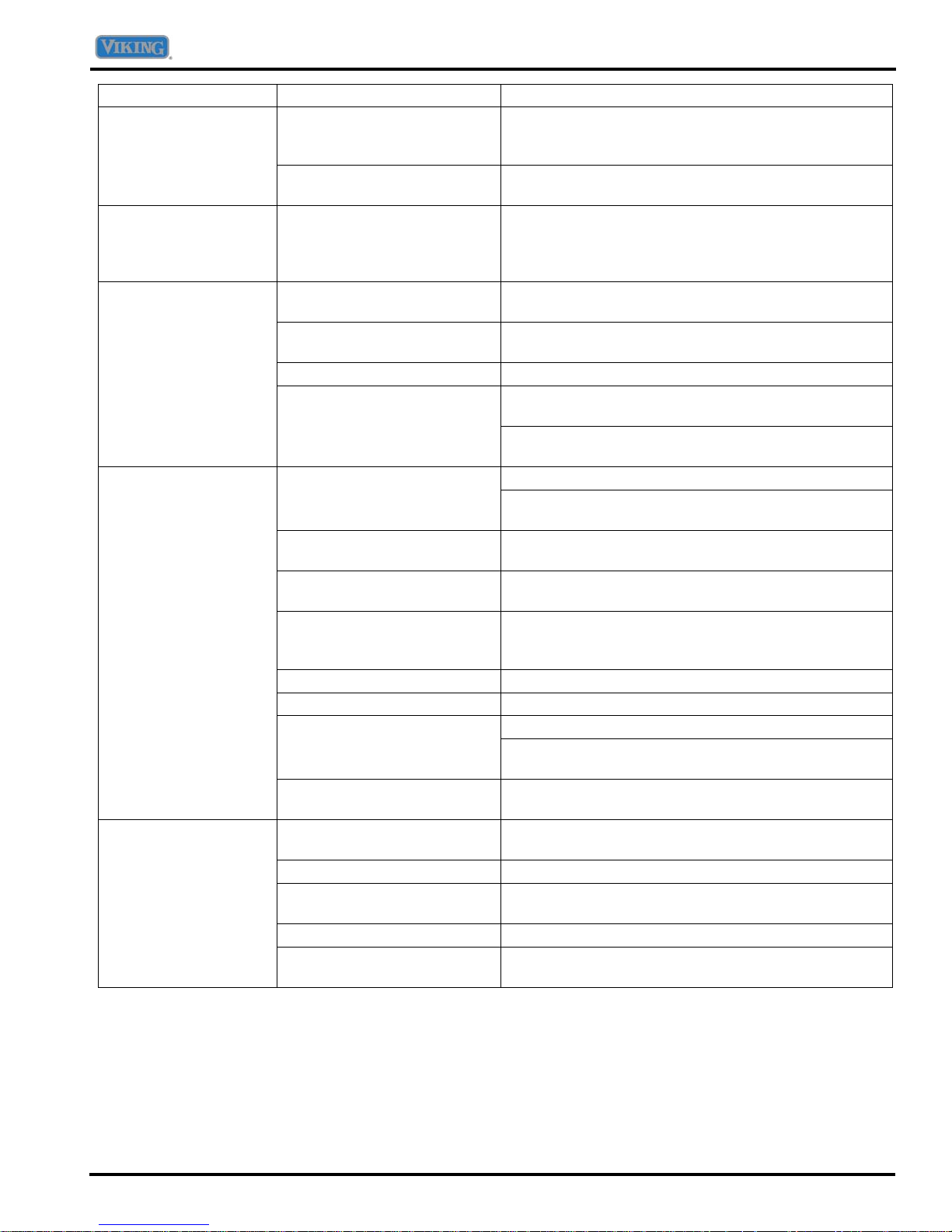
Troubleshooting Chart
Symptom Possible Cause Corrective Action
Water droplets form on
inside of refrigerator
Humidity levels are high or
door has been opened
frequently.
Door gaskets are not sealing
Reduce time door is open. Organize food items
efficiently to assure door is open for as short a time as
possible.
Clean door gasket.
properly.
Refrigerator or ice
Normal operation. See Operating Sounds.
maker makes
unfamiliar sounds or
seems too loud
Temperature-controlled
drawer and/or crisper
drawer do not close
freely
Contents could be obstructing
drawer.
Drawer is not in proper
position.
Reposition food items and containers to avoid
interference with the drawers.
Verify drawer positioning.
Refrigerator is not level. See Leveling.
Drawer channels are dirty.
Clean drawer channels with warm, soapy water. Rinse
and dry thoroughly.
Apply a thin layer of petroleum jelly to drawer
channels.
Refrigerator runs too
frequently
frequently or for long periods
time.
Humidity or temperature in
Reduce time door is open. Doors have been opened
Allow interior environment to adjust for period the door
has been opened.
Normal operation.
surrounding area is high.
Food has recently been
added.
Refrigerator is exposed to
heat by environment or by
Allow time for recently added food to reach
refrigerator or freezer temperature.
Evaluate your refrigerator’s environment. Refrigerator
may need to be moved to run more efficiently.
appliances nearby.
Condenser coils are dirty. Clean coils.
Controls need to be adjusted. Adjust controls.
Refrigerator is not level. Level refrigerator. Door is not closing properly.
Check for internal obstructions that are keeping door
from closing properly.
Door gaskets not sealing
Clean door gaskets.
properly.
No indicator lights are
lit on dispenser control
Freezer door is not closed. Verify that freezer door is closed. Power is removed
from the control when freezer door is opened.
Refrigerator is not plugged in. Plug in refrigerator.
Fuse is blown, or circuit
breaker needs to be reset.
Replace any blown fuses. Check circuit breakers for
any tripped circuits.
Power outage has occurred. Call local power company to report outage.
Refrigerator is in Sabbath
See Sabbath Mode.
Mode.
©2007 Viking Preferred Service 13
Troubleshooting Chart
Symptom Possible Cause Corrective Action
Ice or water are not
dispensed when pads
are pressed
Ice maker is not
producing enough ice
or ice is malformed
Ice maker is not
producing ice
light is red
Water flow is slower
than normal
Water appears cloudy Air or air bubbles in water. This is normal when first using the dispenser and will
Freezer door is not closed. Verify that freezer door is closed. Power is removed
from the control when freezer door is opened.
Controls are in lock mode. See Dispenser Lock.
Water tank is filling. At initial use, there is an approximate one- to two
minute delay in dispensing while the internal water
tank is filling.
Ice maker has just been
installed or a large amount of
ice has been used.
Water filter is clogged or
needs to be changed.
Ice maker has just been
installed or a large amount of
ice has been used.
Water pressure is too low. Check water pressure requirements.
Water filter is clogged or
needs to be changed.
Ice maker arm is up. Confirm ice maker arm is down.
Household water supply is
not reaching water valve.
Copper tubing has kinks. Turn off water supply and remove kinks. If kinks
Water pressure is too low.
Check freezer temperature. Adjust temperature.
Ice bin is not installed
properly.
Improper water valve was
installed.
Water filter needs to be
replaced.
Filter indicator sensor needs
to be reset.
Water pressure is low. Check water pressure requirements.
Saddle valve not open
completely.
Improper water valve was
installed.
Copper tubing has kinks. Turn off water supply and remove kinks. If kinks
Water filter is clogged or
needs to be changed.
Water valve not opened
completely.
Wait 24 hours for ice production to begin or for ice
maker to restock after emptied.
Change water filter.
Wait 24 hours for ice production to begin or for ice
maker to restock after emptied.
Change water filter.
See Connecting the Water Supply.
cannot be removed, replace tubing.
Check water pressure requirements.
Check position of ice bin.
See Connecting the Water Supply.
Change water filter. Water filter indicator
See Filter Status Indicator Light.
Open saddle valve completely.
See Connecting the Water Supply.
cannot be removed, replace tubing.
Change water filter.
Open water valve completely and check for leaks. The
minimum flow at dispenser is approximately 10 fluid
ounces in nine seconds with a new filter in place or
approximately 10 fluid ounces in five seconds without
a filter.
disappear with use.
14 ©2007 Viking Preferred Service
Troubleshooting Chart
Symptom Possible Cause Corrective Action
Ice forms in inlet tube
to ice maker
Water pressure is low.
Saddle valve not open
Check water pressure requirements.
Open saddle valve completely.
completely.
Freezer temperature is too
Adjust temperature.
high.
Refrigerator is leaking
water
Plastic tubing was used to
complete water connection.
Improper water valve was
The manufacturer recommends using copper tubing
for installation.
See Connecting the Water Supply.
installed.
Dispenser water is not
cold
Refrigerator has been
recently installed.
Allow approximately 12 hours for water in holding tank
to chill.
Water supply in holding tank
has been depleted.
Water has settled into water
Discard first glass of water and refill.
lines outside holding tank and
has warmed to room
temperature.
Particles in water
and/or ice cubes
Carbon dust from water filter
cartridge.
Initial water ejected through cartridge may contain
harmless carbon dust flushed from cartridge. Particles
are safe for consumption. Will disappear after the first
few uses.
Concentrations of minerals in
water will form particles when
Particles are not harmful and naturally occur in water
supplies.
water becomes frozen and
melts.
Unit does not run
No power to unit Check for power at outlet. Check fuse box/circuit
breaker for blown fuse or tripped breaker. Replace or
reset.
Faulty power cord Check with test light at unit; if no circuit and current is
indicated at outlet, replace or repair.
Low voltage Check input voltage for proper voltage. Take
appropriate action to correct voltage supply problem.
Faulty motor or temperature
control
Check all connections are tight and secure. Replace if
necessary.
Faulty relay Check relay. Replace if necessary.
Faulty compressor Check compressor motor windings for opens/shorts.
Perform compressor direct wiring test. Replace if
necessary.
Faulty overload Check overload for continuity. Ensure
compressor/overload are below trip temperature
before testing. Replace if necessary.
Freezer and
refrigerator sections
too warm
Temperature controls set too
warm
Poor door seal Level cabinet. Adjust hinges. Replace gasket.
Dirty condenser or obstructed
Reset temperature controls.
Check condenser and grille. Clean.
grille
Faulty control Test control. Replace if failed.
Refrigerant shortage or
restriction
Check for leak or restriction. Repair, evacuate and
recharge system.
©2007 Viking Preferred Service 15
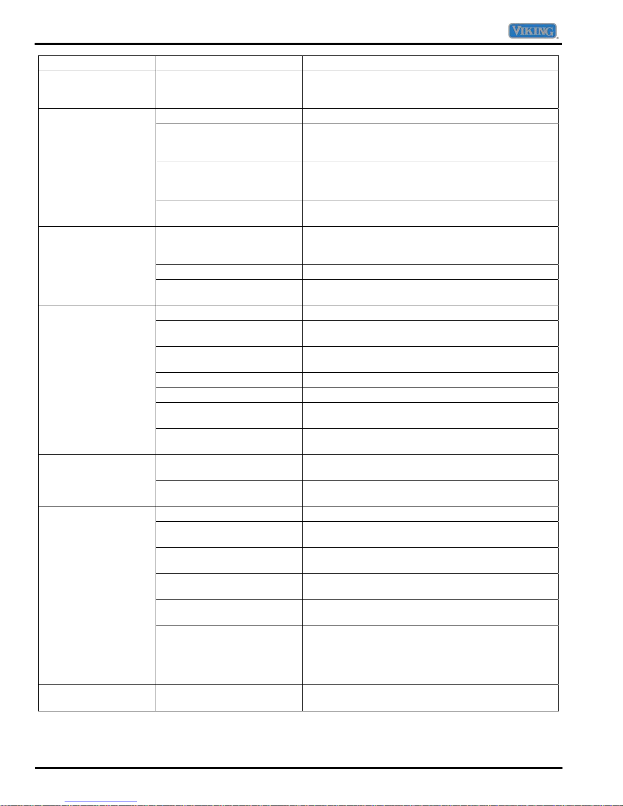
Troubleshooting Chart
Symptom Possible Cause Corrective Action
Refrigerator section too
warm
cold
Frost or ice on
evaporator
Unit starts and stops
frequently (cycles on
and off)
Excessive door opening Consumer education.
Overloading of shelves Consumer education.
Warm or hot foods placed in
cabinet
Cold control set too warm Set control to colder setting.
Poor door seal Level cabinet. Adjust hinges. Replace gasket.
Refrigerator airflow Check damper is opening by removing grille. With
Interior light remains on Check switch. Replace if necessary.
Faulty condenser fan or
evaporator fan
Faulty compressor Replace compressor.
Refrigerator temperature
control set too cold
Refrigerator airflow not
properly adjusted
Defrost thermostat faulty Check defrost thermostat. Replace if failed.
Evaporator fan faulty Check fan motor. Replace if failed.
Defrost heater remains open Check defrost heater continuity. Replace if failed.
Defrost control faulty Check control and replace if failed.
Open wire or connector Check wiring and connections. Repair as necessary.
Refrigerant shortage or
restriction
Loose wire or thermostat
connections
Supply voltage out of
specification
Overload protector open Check overload protector for continuity. If open,
Faulty compressor motor
capacitor (some compressors
do not require motor
capacitor)
Faulty fan motor Check fan motor. Replace if failed.
Restricted air flow Check condenser and grille for dirt. Clean.
Refrigerant shortage or
restriction
Consumer education.
door open, damper should open. Replace if faulty.
Check fan and wiring. Replace if necessary.
Adjust refrigerator temperature control. Refrigerator section too
Check air flow.
Check for leak or restriction. Repair, evacuate and
recharge system.
Check wiring and connections. Repair as necessary.
Check input voltage. Correct any supply problems.
replace overload. Ensure overload/compressor are
below trip temperature before testing.
Check capacitor for open/short. Replace if necessary.
Discharge capacitor before testing.
Check for leak or restriction. Repair, evacuate and
recharge system.
16 ©2007 Viking Preferred Service
Troubleshooting Chart
Symptom Possible Cause Corrective Action
cold
Freezer temp control set too
cold
Adjust freezer temperature control. Freezer section too
Faulty control Test control. Replace if failed.
Unit runs continuously
Temperature control set too
Adjust temperature control.
cold
Dirty condenser or obstructed
Check condenser and grille. Clean.
grille
Poor door seal Level cabinet. Adjust hinges. Replace gasket.
Interior light remains on Check switch. Replace if necessary.
Faulty condenser fan or
Check fan and wiring. Replace if necessary.
evaporator fan
Faulty control Test control. Replace if failed.
Refrigerant shortage or
restriction
Check for leak or restriction. Repair, evacuate and
recharge system.
Refrigerant overcharge Check for overcharge. Evacuate and recharge
system.
Air in system Check for low side leak. Repair, evacuate and
recharge system.
Unit runs continuously.
Ice on evaporator Defrost unit.
Temperature normal
Unit runs continuously.
Faulty defrost thermostat Check thermostat. Replace if necessary.
Temperature too cold
Noisy operation
Loose flooring or floor not firm Repair floor or brace floor.
Cabinet not level Level cabinet.
Tubing in contact with
Adjust tubing.
cabinet, other tubing, or other
metal
Drip pan vibrating Adjust drain pan.
Fan hitting another part Ensure fan properly aligned and all attaching
hardware and brackets are tight and not worn. Tighten
or replace.
Worn fan motor bearings Check motor for worn bearings. Replace if necessary.
Compressor mounting
Tighten hardware. Replace grommets if necessary.
grommets worn or missing.
Mounting hardware loose or
missing
Free or loose parts causing or
allowing noise during
Inspect unit for parts that may have worked free or
loose or missing screws. Repair as required.
operation
©2007 Viking Preferred Service 17
Troubleshooting Chart
Dispenser Troubleshooting Chart
Symptom Possible Cause Test Procedure Corrective Action
No LED lit.
No dispenser light
when water
dispenser pad is
pressed in Water,
Crushed, or Cubed
mode.
Dispenser light is on
(light selections off)
without pressing the
Main or Water
dispenser switch in
Water, Crushed, or
Cubed mode.
Water LED is
illuminated but does
not dispense water
when Main dispenser
switch is pressed.
18 ©2007 Viking Preferred Service
Switch failure in freezer
door.
Incorrect harness wiring. Verify wire color on MPCB 10-pin
No power to the Fountain
Display Board.
No continuity. Disconnect power. Measure
Failed light bulb or Fountain
Display Board.
Failed Main dispenser
switch (failed short).
Failed Fountain Display
Board.
Failed Main dispenser
switch (failed open).
Failed Fountain display
board or MPCB
With unit powered, open freezer
door. Press freezer door switch in.
If freezer light does not turn off,
switch is defective.
connector (J4) and 4 pin connecter
(J1). Refer to Table A.
Verify wire color on Fountain
Display Board 4-pin (J1) and 2-pin
(J2) connectors.
With unit powered, measure
voltage between pin-3 (RD/BK)
wire and pin-1 (BK/GN) wire on
Fountain Display Board. Meter
should read 12VDC.
continuity between VT/BK wire of
door 6-pin connector and WH wire
of door 2-pin connector.
With unit powered, press the Main
dispenser switch. Measure voltage
on VT/BK wire of door 6-pin
connector and WH wire of door 2pin connector. Voltage should read
120 VAC.
Disconnect power. Remove both
leads from the switch and
measure resistance across switch
terminals. Resistance should read
less than 1 Ω in this position and
higher than 10 MΩ when switch is
open.
With unit powered, measure
voltage on VT/BK wire of door 6pin connector and WH wire of door
2-pin connector. Voltage should
read 0 VAC.
Disconnect power. Remove both
leads from the switch and
measure resistance across switch
terminals. Resistance should read
less than 1 Ω in this position and
higher than 10 MΩ when switch is
open.
With unit powered, close main
dispenser switch and press water
pad.
Measure 12 VDC between pin-1
(BK/GN) to pin-4 (LT/BU) on
Fountain Display Board.
Replace switch.
Correct wiring.
Replace Fountain
Display Board if
meter reads 12 VDC.
No 12 VDC, repair
open connection or
replace MPCB.
Replace bulb or
repair open
connection.
Replace dispenser
light bulb or Fountain
Display Board if
voltage reads 120
VAC. No 120VAC,
repair open
connection or
replace MPCB.
Replace switch.
120 VAC or 1/2 the
AC power supply
voltage present,
replace Fountain
Display Board or
MPCB.
Replace switch.
No 12 VDC, replace
Fountain Display
Board. 12 VDC
present, check for
120 VAC on J1 pin-1
(YL/WH) on MPCB.
No 120 VAC, replace
MPCB.
 Loading...