

Viking DCH3042, DCH3642, DWH3006, DWH3606, RDWHC3042 Service Manual
...
Service
Manual
This manual is to be used by qualied appliance technicians only. Viking
does not assume any responsibility for property damage or personal
injury for improper service procedures done by an unqualied person.
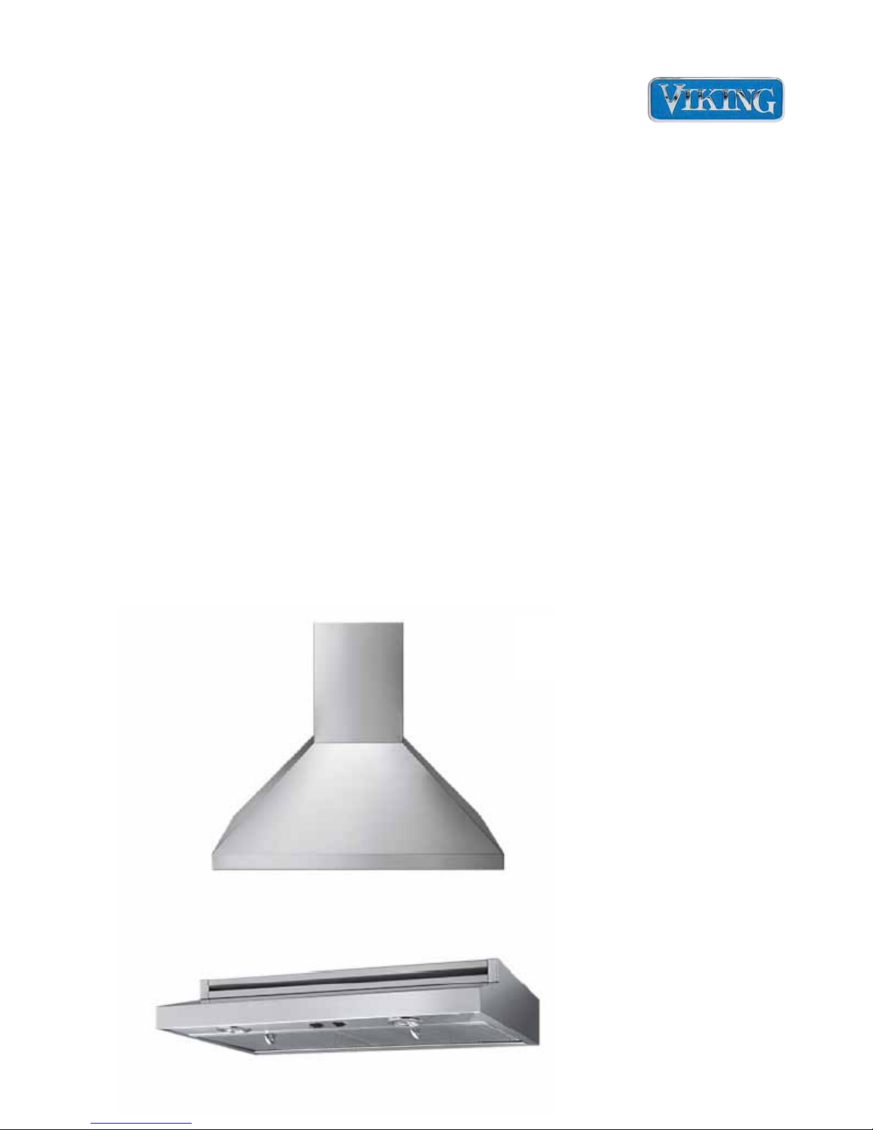
Chimney / Wall
Ventilation
Hoods
®
Preferred Service
This Base Manual covers general and
specic information including, but not
limited to the following models:
Models
DCH3042
DCH3642
DWH3006
DWH3606
RDWHC3042
RDWHC3644
SMV-0001A
April 2012

Table of Contents
Safety Information .......................................................... 3
Save These Instructions........................................... 3
General Information ........................................................ 4
Performance Chart – DWH30SS – DWH36SS ........ 4
Performance Chart – DCH/ RDWHC 30SS – DCH/
RDWHC 36SS ......................................................... 4
DWH30 (30") – DWH36 (36") Designer wall hoods . 5
Filters .................................................................... 6
Motors ................................................................... 6
Ait ow .................................................................. 7
Airow routing ....................................................... 8
Electrical connections ........................................... 8
Disassembly ................................................................... 9
LIGHT OPERATION ................................................11
Troubleshooting .............................................................11
FAN OPERATION (Low Speed) ............................ 12
FAN OPERATION (High Speed) ........................... 13
FAN OPERATION (High Speed Thermostat) ......... 14
FAN OPERATION (High Temperature Thermostat) 15
Wiring Diagrams ........................................................... 16
DWH30/36SS Diagram .......................................... 16
DCH/RDWHC 30SS (30") – DCH/RDWHC 36SS (36")
Professional wall hood ........................................... 17
General Information ...................................................... 17
Disassembly ................................................................. 18
Electrical Connections, Input .............................. 19
Thermostat and Switch access ........................... 20
Dimmer and Motor Speed Controls .................... 21
Troubleshooting ............................................................ 22
LIGHT OPERATION (Low) ..................................... 22
LIGHT OPERATION (High) .................................... 23
MOTOR OPERATION (Low) .................................. 24
MOTOR OPERATION (High) ................................. 25
FAN OPERATION (High Temperature Thermostat) 26
Wiring Diagrams ........................................................... 27
DCH/RDWHC 30/36SS Wiring Diagram ................ 27
B ©2012 Viking Preferred Service
Safety Information
SAVE THESE INSTRUCTIONS
REVIEW ALL SERVICE INFORMATION IN THE APPROPRIATE SERVICE MANUAL AND
TECHNICAL SHEETS BEFORE BEGINNING REPAIRS.
Pride and workmanship go into every product to provide our customers with quality appliances. It
is possible, however, that during the lifetime of a product service maybe require. Products should
be serviced only by a qualied authorized service technician who is familiar with the safety
procedures required to perform the repair and is equipped with the proper tools, parts, testing
instruments, and the appropriate service manual.
Safety Information
We have provided many important safety
messages throughout this manual and on
the product. Always read and obey all safety
statements. To properly identify a safety
statements look for the following safety alert
symbol.
!
This symbol alerts personnel to hazards
that can many different types of altering
messages. All safety messages will be
preceded by a safety alert symbol and the
word “DANGER”, “WARNING” or “CAUTION”.
DANGER!
Immediate hazards which WILL result in severe
personal injury or death.
All safety messages will identify the hazard,
tell you how to reduce the chance of injury,
and inform you what can happen if the
instructions are not followed.
WARNING!
To avoid risk of serious injury or death, repairs
should not be attempted by unauthorized
personnel.
CAUTION!
VIKING will not be responsible for any injury
or property damage from improper service
procedures. If performing service on your own
product, you must assume responsibility for any
personal injury or property damage which may
result.
WARNING!
Hazards or unsafe practices which COULD
result in severe personal injury or death.
CAUTION!
Hazards or unsafe practices which COULD
result in minor personal injury, product or
property damage.
©2012 Viking Preferred Service C
To locate an authorized service agent, call:
Viking Customer Service
Phone No. 1-888-845-4641
Address your written correspondence to:
Viking Preferred Service
1803 HWY 82 West
Greenwood, MS 38930
General Information
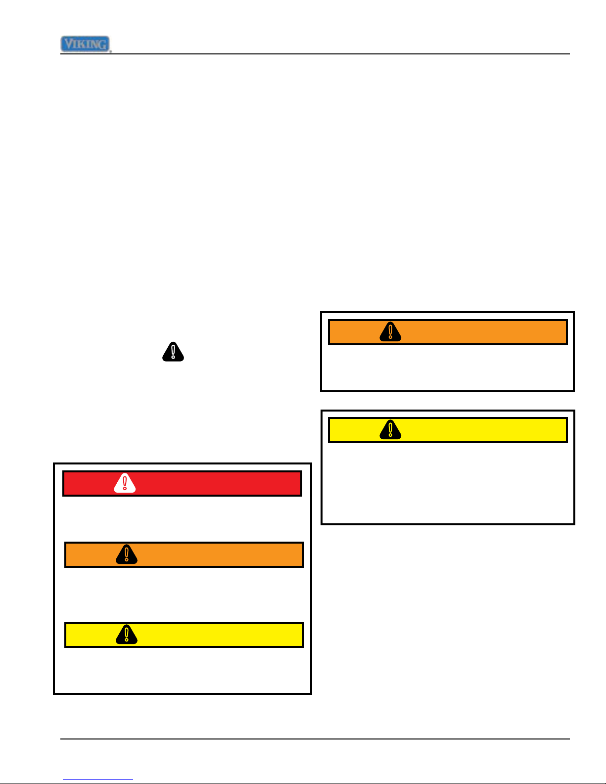
Performance Chart – DWH30SS – DWH36SS
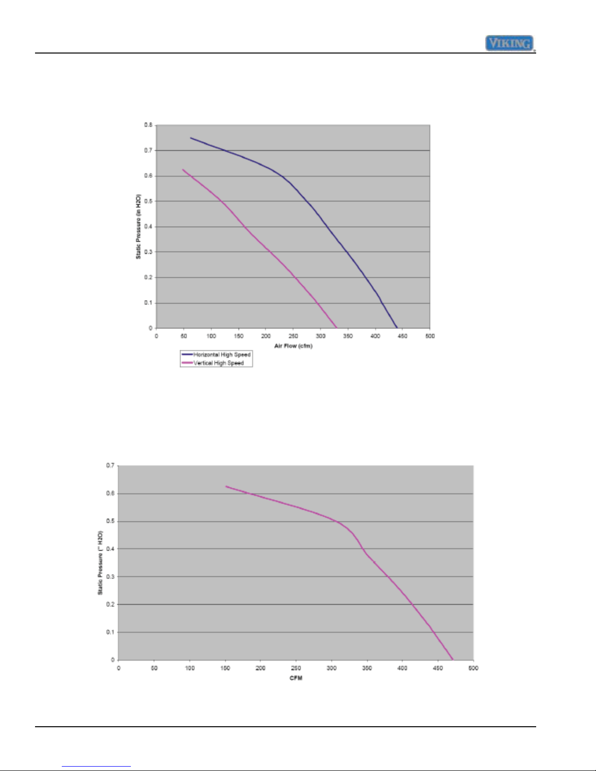
Performance Chart – DCH/ RDWHC 30SS – DCH/ RDWHC 36SS
4 ©2012 Viking Preferred Service
General Information
DWH30 (30") – DWH36 (36") Designer wall hoods
The 30 and 36 inch designer wall hoods are designed to operate both in a recirculation
mode as well as exterior discharge mode. FIG 1 and 2 below shows the underside of the
30" wall hood
FIG. 1 FIG. 2
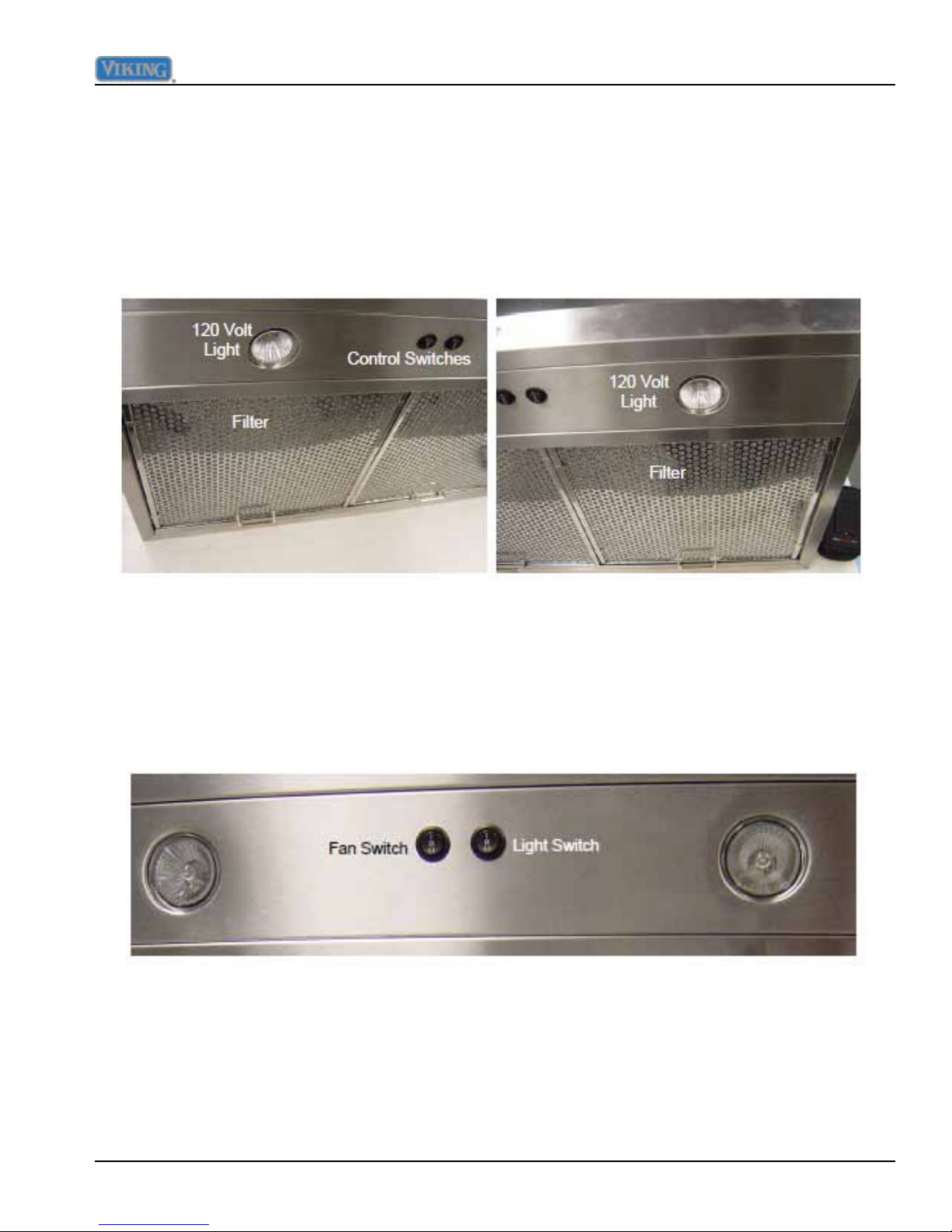
The unit comes with a two-speed dual blower motor and a two level light selection,
both controlled by two center mounted rocker sw itches. Each switch has a center OFF
position. FIG 3 shows a close-up of the switches.
FIG. 3
©2012 Viking Preferred Service 5
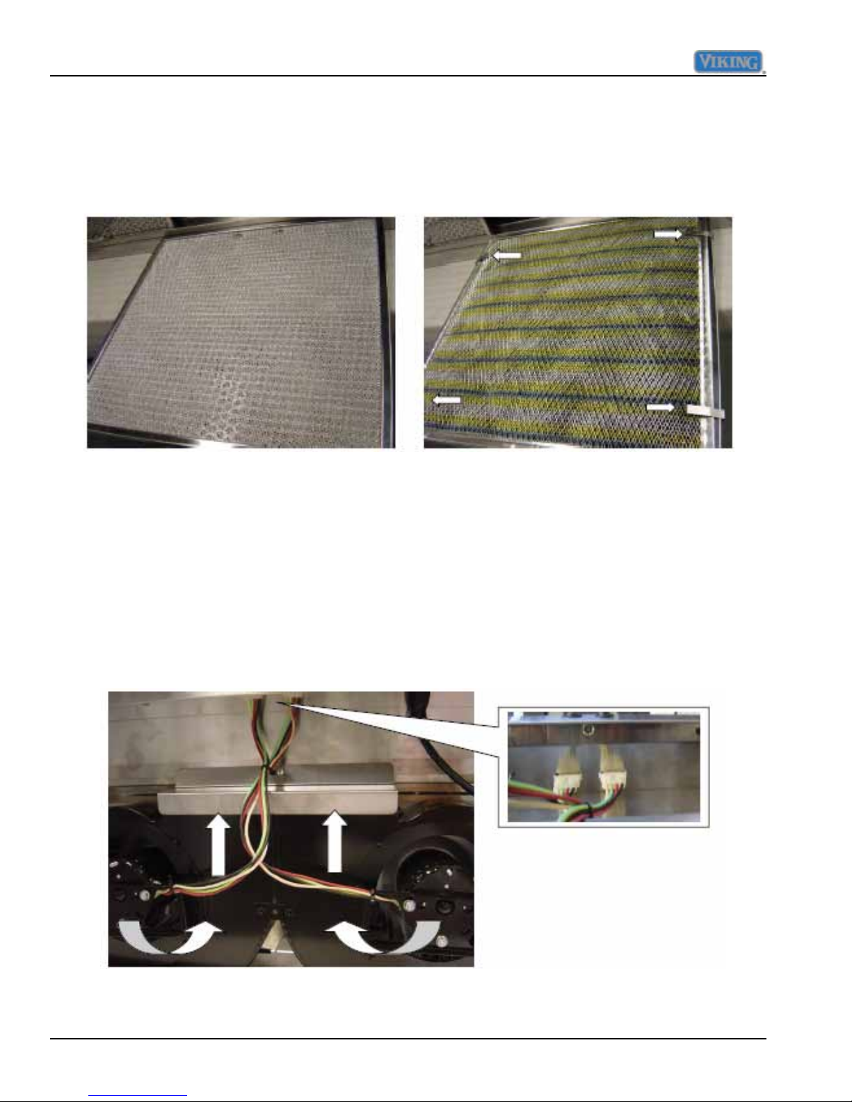
General Information
When the hood is installed to operate in recirculation mode, the addition of charcoal lters
(supplied in kit) is required. FIG 4 shows the standard lter used when the hood is installed
for exterior discharge.
FIG. 5FIG. 4
Standard Filter – Exterior Discharge Recirculation – Charcoal Filter Added
The charcoal lter is held in place with four securing clips (Included with charcoal lter) as
shown in FIG 5 above.
Remove lters to access the internal blower motors. FIG 6 shows that the motor assembly
consists of two motors, one which rotates in a Cloc kwise rotation (Below right) and the other
in a counter-clockwise rotation (Below left). Each motor is connected separately to the control
housing by the use of a 4-wire Molex disconnect plug (Inset).
FIG. 6
Recirculation installation shown
6 ©2012 Viking Preferred Service
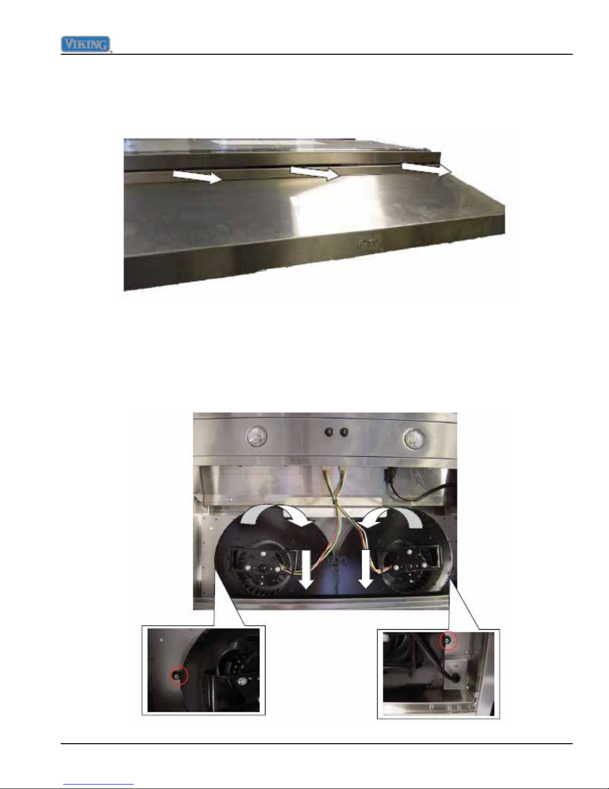
General Information
The air drawn in through the lters is regulated back into the kitchen through a top vent that
runs the length of the hood as shown in FIG 7.
FIG. 7
In FIG 8, the blower motor assembly has been rotated 180° for rear and top external
discharge. There are (2) 5/16th nuts that secure the blower assembly to the hood housing.
The insets below show each side where the nut is located (circled in red). The right one is
just above the main power connection
FIG. 8
©2012 Viking Preferred Service 7

General Information
When the unit is installed for exterior venting, a duct connection collar is attached to the
hood and allows connection to external ducting. FIG 9 shows the hood with the vent collar
attached for rear discharge. Notice a back draft damper is built into the collar. FIG 9 also
shows the top access cover is in place
FIG. 10FIG. 9
FIG 10 shows the rear of the hood with the damper removed. Notice the two squirrel wheels
in place for rear discharge
Junction box (for incoming power supply) is located in upper right rear of hood.. Inside the
hood a three wire power cable exits the junction box (Fig 11) and connects to a xed (male)
three prong plug (FIG 12) in the component compartment of the hood. If the lights and
fan are not working, unplug the internal power plug and check for 120 volts at the female
connection shown in Fig 13.
FIG. 12FIG. 11
Fixed three prong connection
FIG. 13
8 ©2012 Viking Preferred Service
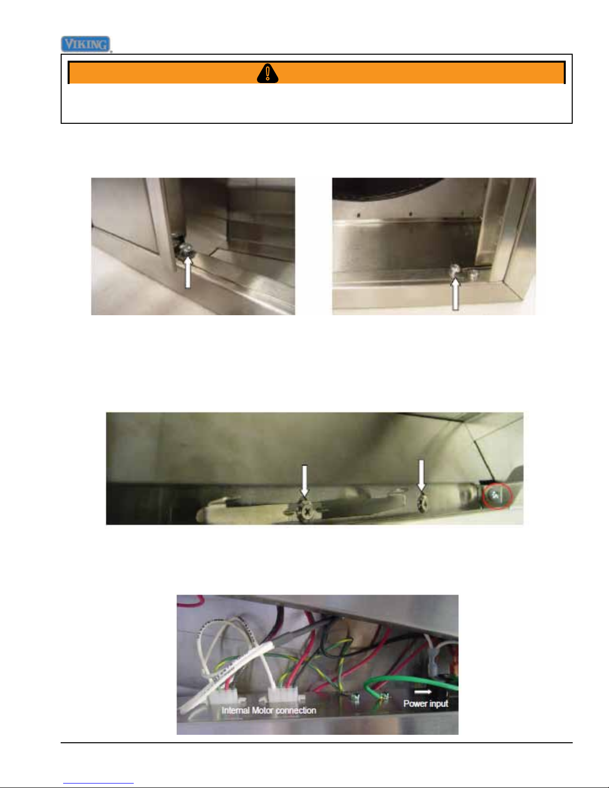
Disassembly
WARNING!
To avoid risk of electrical shock, personal injury, or death, disconnect electrical power source to unit, unless test
procedures require power to be connected. Discharge capacitor through a resistor before attempting to service.
Ensure all ground wires are connected before certifying unit as repaired and/or operational.
To access internal controls, remove left and right side trim held in place with (2) Phillips head
screws shown in FIG 14 and Fig 15.
FIG. 14 FIG. 15
There are ve Phillips head screws that hold the control panel in place. One on each
side, one in the center and two that hold the lter supports in place, FIG 16 shows one of
the side screws and lter support screw. The screw circled in red holds the component
compartment to the main frame and must be removed to access the switches and
thermostats.
FIG. 16
With the screws removed, remove the power and motor connection mounting plate from the
hood. Internal wiring of the power connections is now accessible as shown in FIG 17.
FIG. 17
©2012 Viking Preferred Service 9
 Loading...