

Viking DBCV3638, VBCV3638, DIV300, DIV440, DIV880 Installation Manual
...
Viking Installation Guide
Designer Series
Built-In Custom Ventilator System
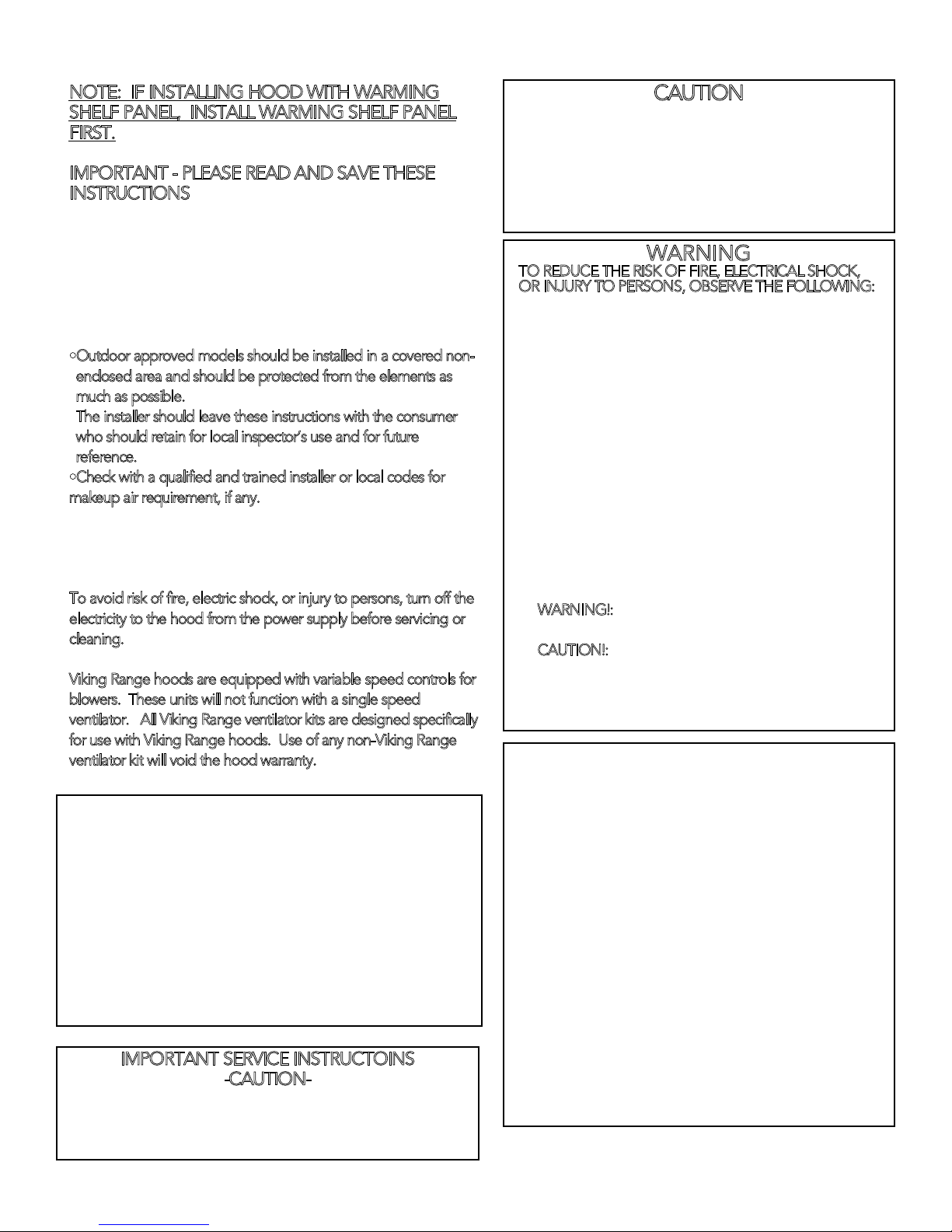
NOTE: IF INSTALLING HOOD WITH WARMING
SHELF PANEL, INSTALL WARMING SHELF PANEL
FIRST.
IMPORTANT - PLEASE READ AND SAVE THESE
INSTRUCTIONS
•Before beginning, please read these instructions completely and
carefully.
•Do not remove permanently affixed labels, warnings, or plates
from the product. This may void the warranty.
•Please observe all local and national codes and ordinances. If no
local codes are applicable, wire in accordance with the National
Electrical Code, ANSI/NFPA 70-1990.
•Outdoor approved models should be installed in a covered nonenclosed area and should be protected from the elements as
much as possible.
he installer should leave these instructions with the consumer
T
•
who should retain for local inspector’s use and for future
reference.
•Check with a qualified and trained installer or local codes for
makeup air requirement, if any.
This hood is for residential installation only and is not designed for
installation over a commercial product. Make sure power is off at
the main circuit breaker or fuse box before making connections.
o avoid risk of fire, electric shock, or injury to persons, turn off the
T
electricity to the hood from the power supply before servicing or
cleaning.
Viking Range hoods are equipped with variable speed controls for
blowers. These units will not function with a single speed
ventilator. All Viking Range ventilator kits are designed specifically
for use with Viking Range hoods. Use of any non-Viking Range
ventilator kit will void the hood warranty.
WARNING - TO REDUCE THE RISK OF FIRE, ELECTRIC
SHOCK, OR INJURY TO PERSONS, OBSERVE THE
FOLLOWING:
1. Use this unit only in the manner intended by the
manufacturer. If you have any questions, contact the
manufacturer.
2. Before servicing or cleaning unit, switch power off at service
panel and lock service panel to prevent power from being
switched on accidentally. When the service disconnecting
means cannot be locked, securely fasten a prominent
warning device, such as a tag, to the service panel.
IMPORTANT SERVICE INSTRUCTOINS
-CAUTION-
For general ventilating use only. Do not use to
exhaust hazardous or explosive materials and
vapors.
CAUTION
TO REDUCE THE RISK OF FIRE, ELECTRICAL SHOCK,
OR INJURY TO PERSONS, RANGEHOODS MUST BE
INSTALLED WITH THE VENTILATORS THAT ARE
SPECIFIED ON THEIR CARTON INDICATING
SUITABILITY WITH THIS MODEL. OTHER VENTILATORS
CANNOT BE SUBSTITUTED.
WARNING
TO REDUCE THE RISK OF FIRE, ELECTRICAL SHOCK,
OR INJURY TO PERSONS, OBSERVE THE FOLLOWING:
1. Installation work and electrical wiring must be done by
qualified person(s) in accordance with all applicable
codes and standards, including fire-rated construction.
2. Sufficient air is needed for proper combustion and
exhausting of gases through the flue (chimney) of fuel
burning equipment to prevent back drafting. Follow
the heating equipment manufacturer’s guideline and
safety standards such as those published by the
National Fire Protection Association (NFPA), and the
American Society for Heating, Refrigeration and Air
Conditioning Engineers (ASHRAE), and the local code
authorities.
3. When cutting or drilling into wall or ceiling, do not
damage electrical wiring and other hidden utilities.
4. Ducted fans must always be vented to the outdoors.
ARNING!:
W
5.
ductwork.
AUTION!:
C
6.
exhaust air, be sure to duct air outside. Do not vent
exhaust air into spaces within walls or ceilings, or into
attics, crawl spaces, or garages.
WARNING - TO REDUCE THE RISK OF INJURY TO
PERSONS IN THE EVENT OF A RANGETOP GREASE
FIRE, OBSERVE THE FOLLOWING:
(based on “Kitchen Firesafety Tips” published by
1. SMOTHER FLAMES with a close-fitted lid, cookie
sheet, or metal tray, then turn off the burner. BE
CAREFUL TO PREVENT BURNS. If the flames do not
go out immediately, EVACUATE AND CALL THE FIRE
DEPARTMENT.
2. NEVER PICK UP A FLAMING PAN. You may be
burned.
3. DO NOT USE WATER, including wet dishcloths or
towels - a violent steam explosion will result.
4. Use an extinguisher ONLY if:
•You know you have a Class ABC extinguisher, and you
already know how to operate it.
•The fire is small and contained in the area where it
started.
•The fire department is being called.
•You can fight the fire with your back to an exit.
To reduce the risk of fire, use only metal
To reduce risk of fire and to properly
NFPA)
2
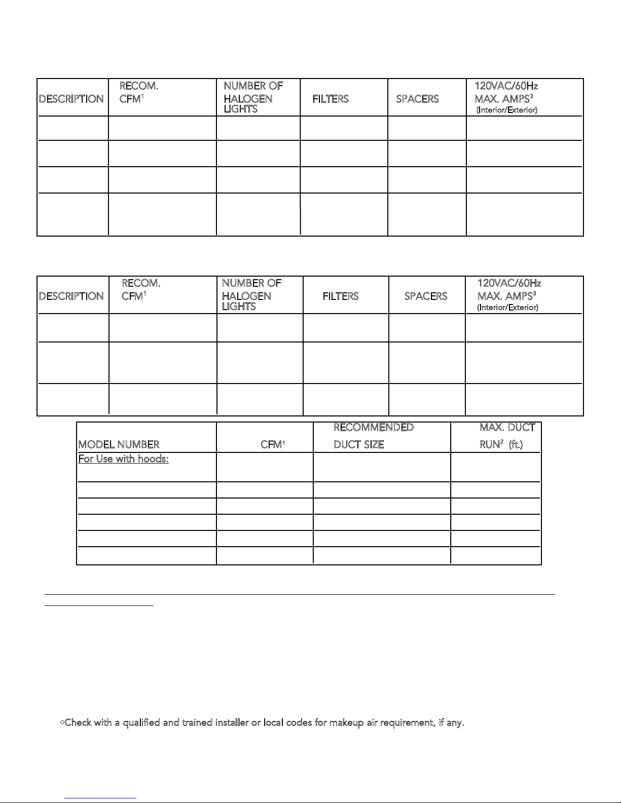
BASIC SPECIFICATIONS
INTERIOR AND EXTERIOR POWER BUILT-IN WALL CUSTOM VENTILATOR SYSTEMS
RECOM. NUMBER OF 120VAC/60Hz
DESCRIPTION CFM
30”W. 300 int./440 int.
36”W. 300 int./440 int.
42”W. 440 int./
48”W. 880 int./
INTERIOR AND EXTERIOR POWER BUILT-IN ISLAND CUSTOM VENTILATOR SYSTEMS
DESCRIPTION CFM
36”W. 440 int. 4 2 1 4.0/
42”W. 440 int./ 4 2 2 4.0/
54”W. 880 int./ 4 3 2 6.4/
1
HALOGEN FILTERS SPACERS MAX. AMPS
LIGHTS
2 2 1
(Interior/Exterior)
1.7/3.2
900 ext./ 1200 ext. 6.6/ 3.9
2 2 1
1.7/3.2
900 ext./ 1200 ext. 6.6/ 3.9
2 3 2
3.2
900 ext./ 1200 ext. 6.6/ 3.9
2 3 2
5.6/
1200 ext. 4.3/
1500 ext. 5.1
RECOM. NUMBER OF 120VAC/60Hz
1
HALOGEN FILTERS SPACERS MAX. AMPS
LIGHTS
(Interior/Exterior)
900 ext./1200 ext. 7.5/5.2
900 ext./ 7.5/
1200 ext./1500 ext. 5.2/ 6.0
1200 ext./ 1500 ext. 5.2/ 6.0
3
3
RECOMMENDED MAX. DUCT
MODEL NUMBER CFM
1
DUCT SIZE RUN2 (ft.)
For Use with hoods:
DIV300 (interior) 300 7” round 50
DIV440 (interior) 440 7” round 50
DIV880 (interior) 880 10” round 50
DEV900 (exterior) 900 10” round* 50
DEV1200 (exterior) 1200 10” round 50
DEV1500 (exterior) 1500 10” round 75
*Must use 8” duct from canopy to ceiling - transition to 10” duct past duct cover
PROPER INSTALLATION/DUCTING IS EXTREMELY IMPORTANT TO ENSURE MAXIMUM PERFORMANCE FROM ANY
VENTILATION PRODUCT
1. •All CFMs stated are based on tests at .1 static pressure: without applying static pressure, CFM would be greatly
overstated.
2. •Duct run length is for general reference only; for longer duct runs, increase duct size and contact a qualified and trained
installer.
•Straight runs and gradual turns are best; for example, each 90oelbow is equivalent to 5-10 feet (1.52 - 3.05 m) of
straight run.
•Never use flexible duct; it creates back pressure/air turbulence and greatly reduces performance.
•Proper performance is dependent upon proper ducting; make sure that a qualified and trained installer is used.
•
Check with a qualified and trained installer or local codes for makeup air requirement, if any.
3. •Max. amp rating for hoods includes recommended ventilator kit rating; all products must be hard wired direct with 2wire with ground.
3
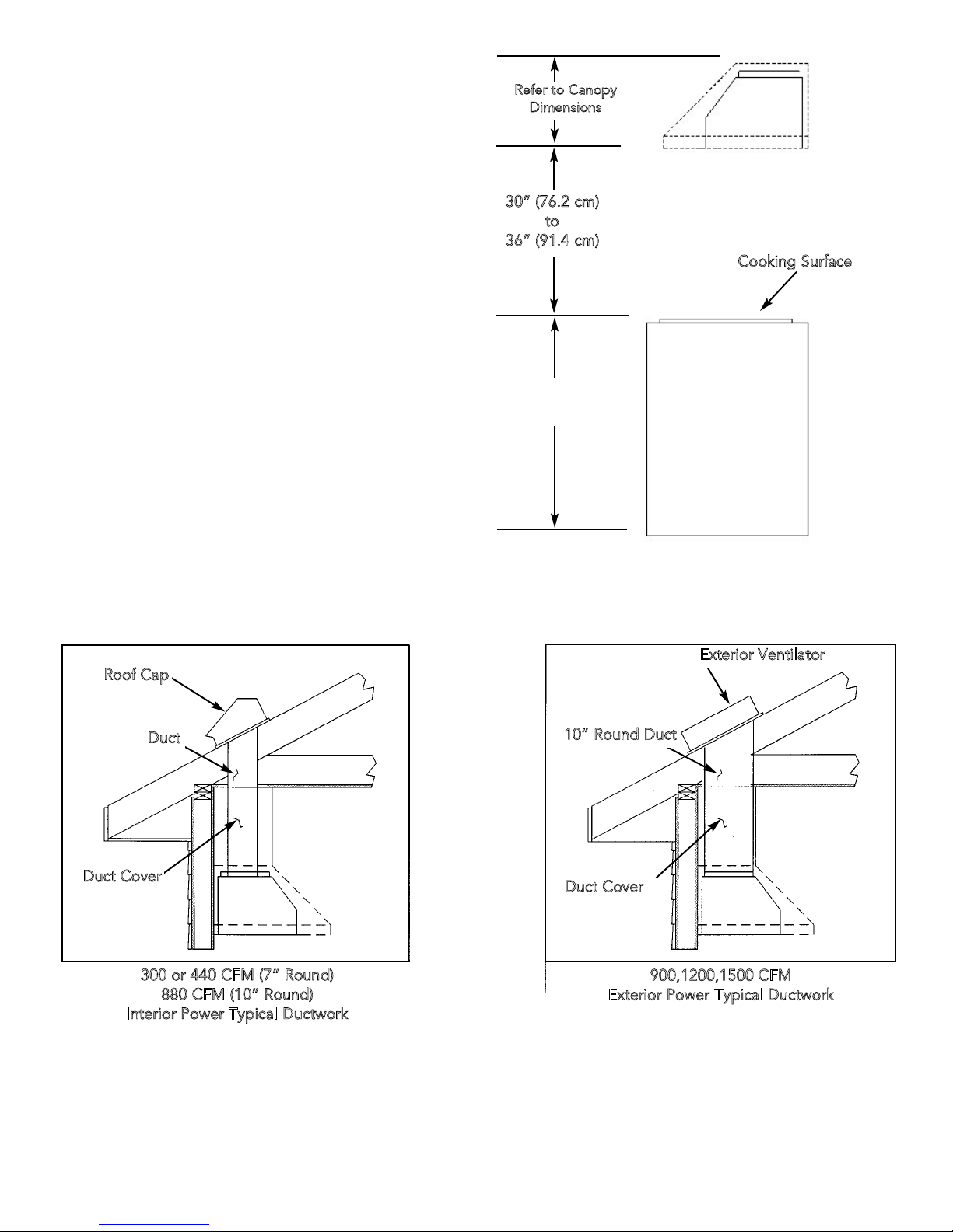
HEIGHT OF HOOD
The bottom of the hood should be 30” (76.2
cm) to 36” (91.4 cm) above the countertop.
This would typically result in the bottom of the
hood being 66” (167.6 cm) to 72” (182.9 cm)
above the floor. For best performance, it is
recommended that the bottom of the hood
be 30” (76.2) to 33” (83.8 cm) above the
countertop. These dimensions provide for
safe and efficient operation of the hood.
Refer to Canopy
Dimensions
30” (76.2 cm)
to
36” (91.4 cm)
Cooking Surface
36”
(91.4 cm)
PREPARING FOR HOOD INSTALLATION
Plan where the ductwork will be located. See pages 12-13 for rough-in dimensions. Install proper-sized duct work, and
roof or wall cap for the type of blower you are using. Adjust your measurements for various heights of ceilings, soffits,
cabinets, or ranges/rangetops.
Exterior Ventilator
Roof Cap
Duct
Duct Cover
300 or 440 CFM (7” Round)
880 CFM (10” Round)
Interior Power Typical Ductwork
10” Round Duct
Duct Cover
900,1200,1500 CFM
Exterior Power Typical Ductwork
ELECTRICAL SUPPLY
Run 120 VAC electrical power cable from service panel to installation location (see dimensions page for exact location).
See “Basic Specifications” on page 15 for the maximum amp requirements.
4
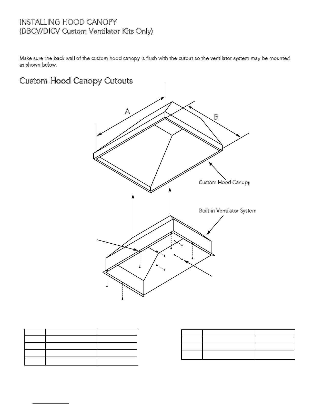
INSTALLING HOOD CANOPY
(DBCV/DICV Custom Ventilator Kits Only)
*For best results, center the unit over the burners of the cooking product (front to back; right to left).
Make sure the back wall of the custom hood canopy is flush with the cutout so the ventilator system may be mounted
as shown below.
Custom Hood Canopy Cutouts
A
B
1) Position ventilator
system inside of the
custom hood canopy
and center it front to
back and left to right.
2) Bottom mounting holes
fasten ventilator system
to bottom of custom
hood canopy with the
screws provided
Custom Hood Canopy
Built-in Ventilator System
3) OPTIONAL
Rear mounting holes fasten
ventilator system to rear of custom
hood canopy
Wall Hoods Island Hoods
A B
30” W. 28 11/16” (72.9 cm) 16 1/2” (41.9 cm)
36” W. 34 11/16” (88.1 cm) 16 1/2” (41.9 cm)
42” W. 40 11/16” (103.4 cm) 16 1/2” (41.9 cm)
48” W. 46 11/16” (118.6 cm) 16 1/2” (41.9 cm)
36” W. 34 11/16” (88.1 cm) 21 1/2” (54.6 cm)
42” W. 40 11/16” (103.4 cm) 21 1/2” (54.6 cm)
54” W. 52 11/16” (133.8 cm) 21 1/2” (54.6 cm)
A B
5
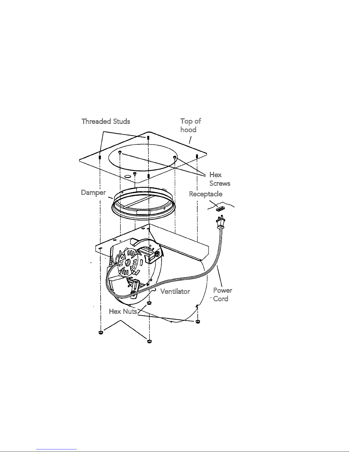
VENTILATOR KIT INSTALLATION
DIV300/DiV440
(Also see instructions supplied with ventilator kit)
1. Attach DAMPER to VENTILATOR, as shown, using three (3) HEX SCREWS (provided). Note: Damper flange to be
captured by screw heads.
2. Lift ventilator into position inside the hood.
3. Fasten ventilator to four (4) THREADED STUDS, using four (4) HEX NUTS (provided).
4. Plug ventilator's POWER CORD into RECEPTACLE inside the hood.
5. NOTE: This installation does not use the mounting plate and (4) additional hex nuts. They may be discarded.
Threaded Studs
Damper
Top of
hood
Hex
Screws
Receptacle
Hex Nuts
Ventilator
6
Power
Cord
 Loading...