

Page 1
BLK-1A
BLK-1A
Line Status
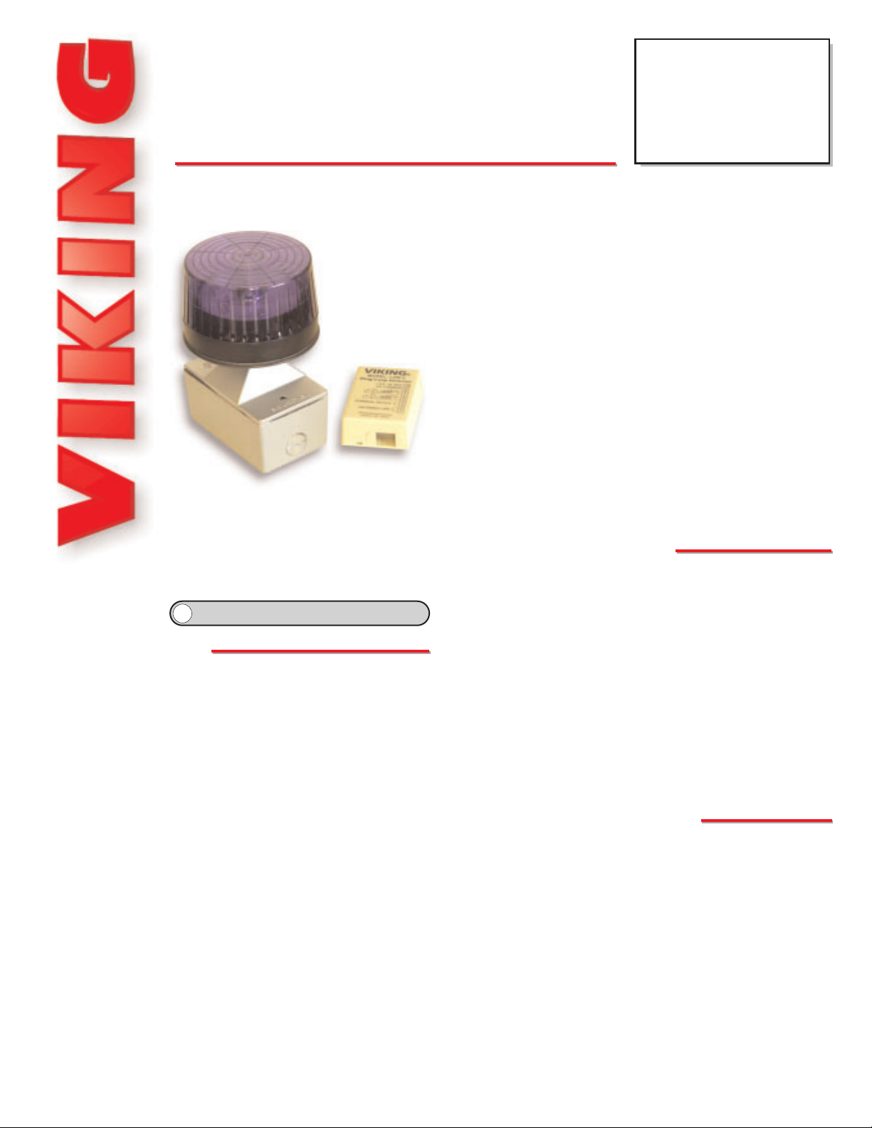
Strobe Light Kit
December 26, 2001
PPrraaccttiicce
e
T
T
EELLEECCOOM
M
S
S
OOLLUUTTIIOONNSSFFOORRTTHHE
E
221
1
SST
T
C
C
EENNTTUURRY
Y
TECHNICAL
TECHNICAL
The BLK-1A provides high visibility indication of analog line status
through a high powered one million candle power strobe light. The
BLK-1A is the ideal solution for the hearing impaired and can be used
equally well in loud warehouses or factories, where ringing phones can
not be heard. Alternatively, the BLK-1A can be used to add emergency
notification to pre-existing emergency phones by turning
on the strobe light when the emergency phone is in use.
The kit includes: (1) control module, (1) blue strobe light,
(1) 12V DC power adapter, (1) single gang weatherproof
mounting box with gaskets and hardware, (2) wire nuts,
and 20 feet of wire.
The control module can be installed on any standard telephone line or
hhttttpp::////wwwwww..vviikkiinnggeelleeccttrroonniiccss..ccoom
m
• Vandal resistant polycarbonate lens
• Strobe and control module may be installed
separately
• Long life 1 million candle power blue strobe
light
• Flush mount or surface mount with
weather proof single gang box (included)
• 3/4” knockouts for connecting conduit, etc.
• Easy terminal screw installation
• Can be configured to signal ringing or a
combination of both ringing and off-hook
(line in-use)
• Auxiliary relay contact output provided
FFeeaattuurrees
s
PPhhoonnee......771155..338866..8888661
1
iinnffoo@@vviikkiinnggeelleeccttrroonniiccss..ccoom
m
Power: 120V AC to 12V DC adapter provided
Strobe Dimensions: 111mm diameter x 69mm (4.38" x 2.75")
Control Module Dimensions: 74mm x 53mm x 25mm (2.9" x
2.1" x 1.0”)
Shipping Weight: 1.5 kg (3.3 lbs)
Operating Temperature: -26° to 54°C (-15° to 130° F)
Contact Rating: .5A @ 125V AC/1A @ 30V DC
Minimum Loop Current: 15 mA
Minimum Ring Voltage: 40 V RMS
Strobe Output: 1 million candle power @ 1 second flash rate
Ringer Equivalence: 0.5 A REN
Connections: 10 pin screw terminal block and (2) wire nuts
Control Module Mounting: (2) screws (not included) or foam
tape (included)
Strobe Mounting: Fasten to wall, post, etc. with complete surface mounting hardware included
AApppplliiccaattiioonns
s
SSppeecciiffiiccaattiioonns
s
analog PABX/KSU station. The 1 million candle power strobe can be interfaced to flash on ringing or a combination of ringing and
off-hook (line in-use).
The LDB-2 ring/loop detect control
module is also available separately.
Provide Strobe Light Indication
of Line Status
• Ringing Phone or TTY indication for the
hearing impaired
• Ringing phone indication in loud warehouses
and factories
• Emergency illumination for emergency
phones in elevators, campuses, hallways,
parking ramps, etc.
• Alarm indication for security systems or alarm
panels with phone dialers
?
?
Need More Information on the LBD-2?
Call (715) 386-4345 and select 408.
Page 2
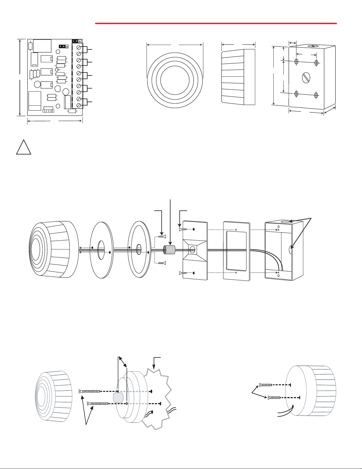
IInnssttaallllaattiioon
n
A. Installing the Strobe Light
2.75”
(2) #8-32 x 2 1/2 Phillips
Head Self Tapping
Screws (included)
(2) #10-32 x 5/8
Phillips Head Self
Tapping Screws
(included)
To LDB-2
Control Module
(included)
Strobe Light
(included)
1. Using the Included Weatherproof Box
2. Front Mounting Without the Weatherproof Box
The BLK-1A Strobe Light Kit may be mounted without
using the included weatherproof box. To mount the
strobe light from the front, use the diagram below.
To mount the strobe light from the rear, use the
diagram below.
1
2
3
4
5
6
7
8
9
10
12VDC
Relay Contact
Output
Auxiliary Relay
Contact Output
Phone
Line
Back view of weatherproof
single gang box (included)
Front View of the
Strobe Light (included)
3. Rear Mounting Without the Weatherproof Box
IMPORTANT: Electronic devices are susceptible to lightning and power station electrical surges from both the AC outlet and the
telephone line. It is recommended that a surge protector be installed to protect against such surges. Contact Panamax at (800)
472-5555 or Electronic Specialists Inc. at (800) 225-4876.
!
Side View of the
Strobe Light (included)
Strobe Light
(included)
To LDB-2
Control Module
(included)
Wall, post, etc.
4.60
2.84
1 2 3 4 5 6 7 8 9 10
(2) 10-32 x 3/8" self
tapping screws
4.38
diameter
Nipple 1/2" x close
(2) 6-32 x 3/4" screws
2.75
0.6
1.05
4.60
2.50
1.50
2.84
(2) Knockout
Plugs
2.0
Blue Strobe
Light
Foam
Gasket
Strobe
Mounting Ring
1/2" Close Nipple
Faceplate
Foam
Gasket
Weatherproof
Box
Page 3

B. Mounting the LDB-2 Control Module
12V DC
Adapter
(included)
Incoming
Phone Line
Rear View of the
Strobe Light
(included)
Wire Nuts
(included)
12V DC
Adapter
(included)
Control Module
(included)
Rear View of the
Strobe Light
(included)
Wire Nuts
(included)
20 Feet of Wire (included)
20 Feet of Wire (included)
Black
(-)
(+)
Red
Incoming
Phone Line
Phone
(not included)
Black
(-)
(+)
Red
Auxiliary Contact Output
Turns on the strobe light and provides an auxiliary contact closure
during ringing only.
Step 1. Remove the cover from the control module.
Step 2. Mount the unit on a wall, using either screws or the included foam
tape. Make sure there is easy access to the internal terminal
block. The internal board of the control module can be rotated
exposing the two mounting holes in the chassis.
Step 3. Once mounted, swing the board back into position and attach wires.
Step 4. Replace cover making sure wires protrude through rectangular wire
pass-through.
The control module is designed to be wall mounted using either screws
or the included foam tape.
D. Configuring the BLK-1A for Both Ring and Loop Indication
Turns on the strobe light and provides an auxiliary contact closure
during ringing and when the phone
is in use.
Black
(-)
(+)
Red
Black
(-)
(+)
Red
Note: For information on installing the BLK-1A with the E-1600-20A see
Other Applications.
A. Adjustable Relay Closure Time Out
The time out POT (see diagram to the right) can be adjusted from 2 to 6 seconds.
Turn the time out POT counter clockwise to decrease the closure time. Turn it clockwise to increase the closure time. When monitoring for ring, turning the time out POT
fully clockwise will allow the relay closure to be maintained (strobe will continue flashing) during the entire off time of the ring signal. When monitoring for loop, the relay
closure will be maintained while off-hook and will time out following an on-hook (strobe
will continue to flash until time-out occurs).
PPrrooggrraammmmiinng
g
The auxiliary relay contact located at terminal pins 5 & 6 can be used to control other
equipment. It can be set for normally open (N/O) or normally closed (N/C) by repositioning JP1 (see diagram to the right). Note: JP2 should be left in the normally open
position (N/O ) for controlling the strobe light.
JP2
JP1
B. Relay Contact Selections
Auxiliary relay contact set to normally open (N/O).
Auxiliary relay contact set to normally closed (N/C).
Auxiliary Contact Output
Control Module
(included)
C. Configuring the BLK-1A for Ring Indication Only
LDB-2 Control Module
1 2 3 4 5 6 7 8 9 10
V
IK
IN
MODEL: LDB-2
G
©
Wire PassThrough
Mounting
Hole
1 2 3 4 5 6 7 8 9 10
Time Out
1 2 3 4 5 6 7 8 9 10
1 2 3 4 5 6 7 8 9 10
Page 4

Due to the dynamic nature of the product design, the information contained in this document is subject to change without notice. Viking Electronics, and its affiliates and/or
subsidiaries assume no responsibility for errors and omissions contained in this information. Revisions of this document or new editions of it may be issued to incorporate
such changes.
Fax Back Doc 652
ZF301650 Rev A
Printed in the U.S.A.
OOppeerraattiioon
n
When the LDB-2 detects an incoming ring signal, it activates a relay opening or closing the contacts across terminals
5 & 6 and 7 & 8 (depending on placement of JP1 and JP2). When wired as shown in Installation section C, and the
time-out POT is in the maximum position, the blue strobe light will flash during the entire ring cadence (on and off
cycles) and will stop flashing approximately 6 seconds after ringing has stopped.
A. Ring Indication
When the LDB-2 detects an off-hook condition (loop current) on terminals 3 & 4, it activates a relay opening or closing
the contacts across terminals 5 & 6 and 7 & 8 (depending on placement of JP1 and JP2). When wired as shown in
Installation section D, and the time-out POT is set to minimum, the blue strobe light will flash during the entire off-hook
condition and will stop flashing approximately 2 seconds after the phone on terminals 3 & 4 has gone back on hook.
B. Off-Hook Indication
OOtthheerrAApppplliiccaattiioonns
s
B. Controlling (4) Separate Strobe Lights C. Operating a BLK-1A with a Contact Closure
PPrroodduuccttSSuuppppoorrttLLiinnee......771155..338866..8866666
6
FFaaxxBBaacckkLLiinnee......771155..338866..4433445
5
A. Mounting the LDB-2 with the E-1600-20A
Step 1. Drill or use a knockout punch to provide a .875”
diameter hole in top of the VE-5x5.
Step 2. Make all conduit connections.
Step 3. Remove the LDB-2 circuit board from chassis.
Step 4. Make all wire connections to the LDB-2 circuit board.
Step 5. Using the double-backed tape provided, adhere the
LDB-2 circuit board (no chassis) to the inside right
hand wall of the VE-5x5 with the power connector
closest to the back wall as shown right.
Step 6. Install the E-1600-20A as explained in its Technical
Practice.
The BLK-1A Strobe Kit can be used in conjunction with the E-1600-20A Two-Button Phone as shown
to the far right, however, special installation and mounting is required. Please follow the steps below
when using the BLK-1A in conjunction with a surface-mounted E-1600-20A.
E-1600-20A shown
with VE-5x5
?
?
Need More Information on the VE-5x5?
Call (715) 386-4345 and select 424.
?
?
Need More Information on the E-1600-20A?
Call (715) 386-4345 and select 215.
6 7 8 9 10
4 5
1 2 3
LDB-2 Circuit
Board (included)
Front View of Optional
VE-5x5 (not included)
1/2" Liquid Tight
Conduit Connector
1/2" PVC Conduit
Conduit Connector
Straps
1/2" Liquid Tight
Conduit
1/2" Liquid Tight
12V DC
Adapter
(included)
1 2 3 4 5 6 7 8 9 10
To Phone Line
To Phones
12V DC, 1.5 Amp minimum
Regulated Power Supply
(Radio Shack part # 22-504
or equivalent)
Black (-)
To Strobe #1
Red (+)
Black (-)
To Strobe #2
Red (+)
Black (-)
To Strobe #3
Red (+)
Black (-)
To S tr obe #4
Red (+)
To Normally Open (N/O)
12V DC
Adapter
(included)
Contact Closure.
When closed, the
strobe light is on.
1 2 3 4 5 6 7 8 9 10
1000 Ohm 1/4 Watt Resistor
(Radio Shack part # 271-1321
or equivalent)
Black (-)
To Strobe
Red (+)
Light
 Loading...