

Page 1
January 12, 2007
OBSOLETE
Deluge Devices 270a
TECHNICAL DATA
The Viking Corporation, 210 N Industrial Park Road, Hastings MI 49058
Telephone: 269-945-9501 Technical Services 877-384-5464 Fax: 269-945-4495 Email: techsvcs@vikingcorp.com
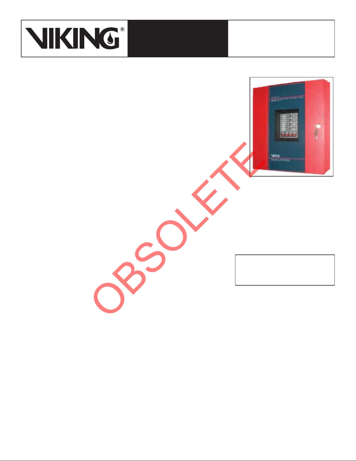
MODEL B-1
1. DESCRIPTION
RELEASE CONTROL PANEL
The Viking Model B-1 Par-3 Release Control Panel is a supervised, 24 Volt, microprocessorcontrolled Release Control Panel. The panel is designed to operate up to two electric release
devices (usually solenoid valves) in the release piping of deluge or preaction systems. The
panel is available for use with either 120 VAC or 230 VAC power supplies. A built-in battery compartment holds two 12 Volt batteries that are charged by an internal battery charger. Batteries
are available to provide up to 90 hours of backup power during AC power failure.
The Model B-1 Release Control Panel can be used with a wide range of compatible initiating
devices, such as heat (including linear heat detection systems like the Protectowire Systems),
photoelectric, ionization, and smoke detectors.
A dip switch ‘Function Selector’ allows fi eld programming for one of four possible input/output
combinations (refer to Table 2).
In fi re conditions, when an initiating device circuit (or predetermined combination of circuits) is
energized, the panel activates a combination of release device circuits and alarm circuits according to the ‘Function Selector’ setting. On the panel’s display board, the appropriate Alarm,
Trouble, and Supervisory LED’s will fl ash until the event has been acknowledged. After depress-
ing the Tone or Alarm Silence button, the LED will remain steadily illuminated until the panel is
reset.
2. LISTINGS AND APPROVALS
Refer to Table 1
3. TECHNICAL DATA
I. Specifications
A. Enclosure
•
Dimensions: 16.125” high x 14.625” wide x 5.375” deep (50 cm x 37,1 cm x 13,7 cm)
•
Weight: 23 lbs. (10,4 kg)
•
Finish: Red Enamel
•
Vented Enclosure
B. Environment
•
Temperature: 32 °F to 120 °F (0 °C to 48 °C)
•
Humidity: 85% Relative Humidity (non-condensing) at 90 °F (32 °C) maximum
C. AC Power
•
Par-3 and Par-3C: 120 VAC, 50/60 Hz, 1.2 amps
•
Par-3E: 230 VAC, 50 Hz, 0.65 amps
•
Wire size: minimum #14 AWG with 600 V insulation
D. Battery
•
Type- Lead Acid
•
Maximum charging circuit: 27.6V, 1.5 A See ACCESSORIES for batteries available from Viking.
E. Initiating Device (Input) Circuits
•
Four style B (Class B)/Style D (Class A) circuits
•
Input 1: Detection Circuit
•
Input 2: Detection Circuit
•
Input 3: Waterfl ow (Alarm Pressure Switch)
•
Input 4: Supervisory Circuit
F. System Alarm
•
Power limited circuitry
•
Fuses: 2AG, 4 amperes
•
Normal operating voltage: 24VDC (ripple = 10mV peak to peak)
•
Alarm Current: 15mA minimum
•
Short circuit current: 40mA maximum
•
Maximum detector current in standby: 2 milliamps (peak) per zone
•
Maximum loop resistance: 100 ohms
•
End-of-Line resistor: 4.7K (provided)
Viking Technical Data may be found on
The Viking Corporation’s Web site at
http://www.vikinggroupinc.com.
The Web site may include a more recent
edition of this Technical Data Page.
Form No. F_063092
Revised page replaces page 270 a-g dated August 17, 2006
(Added California State Fire Marshal approval)
Page 2
Deluge Devices 270b
OBSOLETE
January 12, 2007
TECHNICAL DATA
The Viking Corporation, 210 N Industrial Park Road, Hastings MI 49058
Telephone: 269-945-9501 Technical Services 877-384-5464 Fax: 269-945-4495 Email: techsvcs@vikingcorp.com
Note: leave E-O-L resistors provided, on all unused circuits.
•
Detector loop current is suffi cient to ensure operation of one alarmed
•
detector per zone.
Supervisory current: 5mA (including End-of-Line Resistor)
•
G. Heat Detectors:
Detection circuits allow for installation of any number of listed or ap-
•
proved normally open thermal detectors.
H. Smoke Detectors:
•
Contact the Viking distributor for a list of compatible smoke detectors,
information concerning the maximum number of smoke detectors
allowed per zone, and standby power requirements for the smoke
detector used. Also, refer to appropriate Fire Protection Equipment
Approval Guides.
•
For supervised four-wire smoke detectors, connect the Power Supervision Relay to the last detector base 24V screw terminals.
•
See ACCESSORIES.
I. Indicating Appliance and Releasing (output) Circuits
•
Two Style Y and two Style Y/Z circuits
•
Output 1: Alarm Bell(Style Y/Z)
•
Output 2: Waterfl ow or Trouble Horn (Style Y/Z)
•
Output 3: Releasing Circuit 1 (Style Y)
•
Output 4: Releasing Circuit 2 or Trouble Horn(Style Y)
•
Normal operating voltage: 24VDC
•
Total current available to all four circuits + RMS regulated power
output circuit, not to exceed: 2.25 AMPS
•
Maximum signaling current per circuit: 2.25 AMPS
•
Supervised Circuitry Power limited circuitry (except for Municipal
Box output)
•
Fuses: 2AG, 4 amperes
•
Maximum allowable voltage drop due to wiring: 2 VDC.
•
End-of-Line resistor: 4.7K (provided)
•
Note: leave E-O-L resistors provided, on all unused circuits.
•
Note: Wiring must be confi gured to maintain a minimum voltage of 20.4V on release circuits.
•
Contact the Viking distributor for a list of compatible indicating appliances and releasing devices. Also, refer to Viking Technical
Data and appropriate Fire Protection Equipment Approval Guides.
J. Alarm Relay
•
Basic panel includes one non-silenceable Form-C dry alarm contact rated 2 amps at 30 VDC and 0.5 amps at 30 VAC (resistive).
K. Trouble Relay
•
Basic panel includes one Form-C dry alarm contact rated 2 amps at 30 VDC and 0.5 amps at 30 VAC (resistive). Trouble relay
will silence when trouble condition is cleared.
L. Zone Relay Module
•
Model B-1 Panels include one Zone Relay Module (4XZM) providing dry Form-C contacts controlled by each of the four output
circuits plus one general alarm and one panel/fi eld-wiring trouble relay. See Table 2.
M. Power Outputs
•
Four-wire Smoke Detector Power (resettable): Up to 200 mA total (four-wire smoke detector power plus non-resettable power
combined) DC current available. Maximum ripple voltage: 10mV p/p.
•
Non-resettable Power: Up to 200 mA total (four-wire smoke detector power plus non-resettable power combined) DC current
available.
•
Maximum ripple voltage: 10mV p/p.
•
RMS Regulated Power: Total current available for external devices: 0.5 amp (subtracted from 2.25 A available to indicating appliance circuits) DC current available.
•
Maximum ripple voltage: 100mV p/p.
MODEL B-1
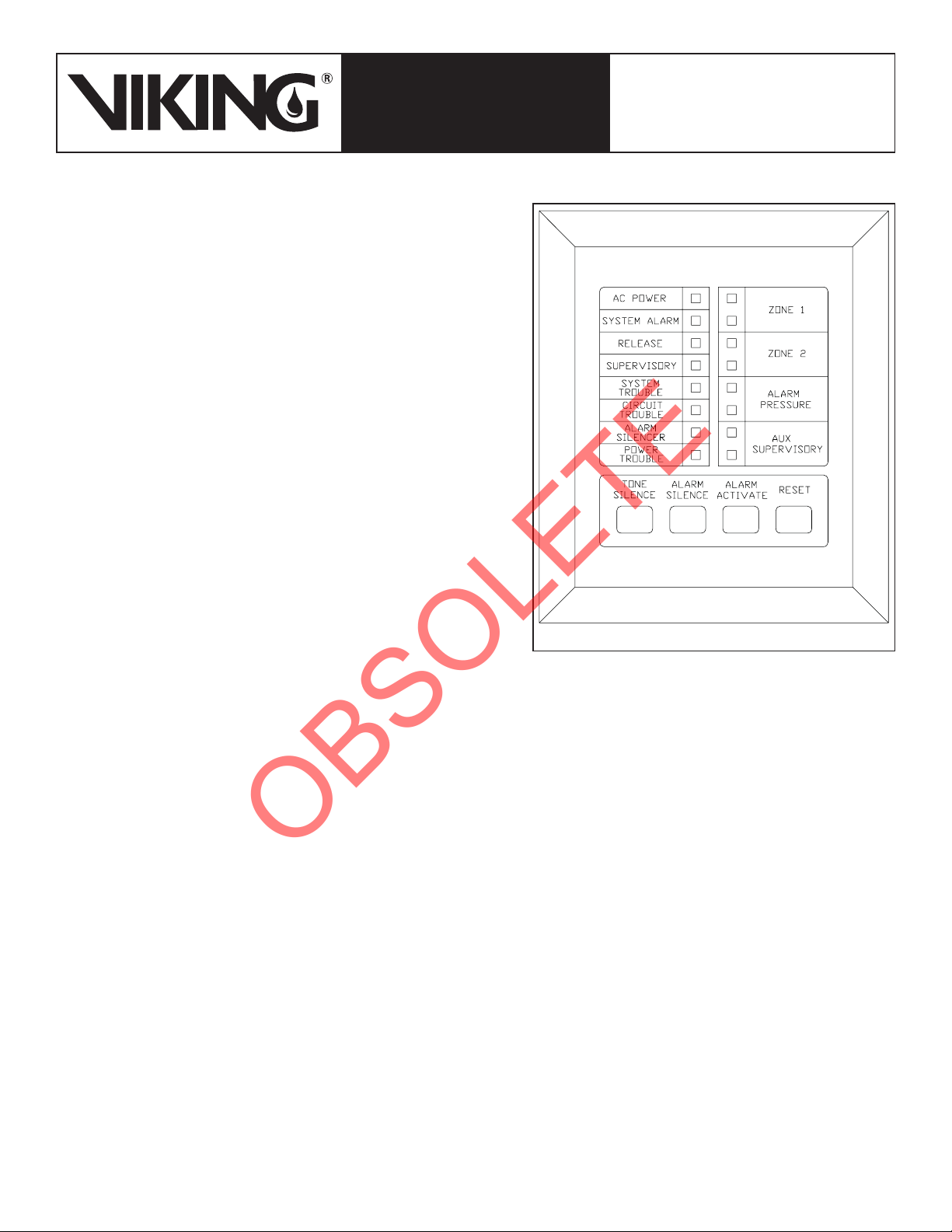
Figure 1
RELEASE CONTROL PANEL
Page 3

January 12, 2007
OBSOLETE
Deluge Devices 270c
TECHNICAL DATA
The Viking Corporation, 210 N Industrial Park Road, Hastings MI 49058
Telephone: 269-945-9501 Technical Services 877-384-5464 Fax: 269-945-4495 Email: techsvcs@vikingcorp.com
N. Front Panel Control Switches (Refer to Figure 1)
•
Switch 1: Tone Silence
•
Switch 2: Alarm Silence - Tone Silence and Alarm Silence control switches can be activated to acknowledge alarms. A second
“trouble” will resound the piezo.
•
Switch 3: Alarm Activate -The Alarm Activate switch may be used to activate indicating circuits and relays.
•
Switch 4: System Reset - The Reset switch clears any activated output circuits. If alarm or trouble conditions exist when the reset
switch is pushed, they will re-activate the panel.
O. Front Panel Zone Status LEDs
•
When the panel is activated, zone status LEDs illuminate, to indicate the status of Zone 1, Zone 2, Alarm Pressure, and Auxiliary
Supervisory circuits.
•
Alarm (red) LEDs indicate activation of a detection device.
•
Trouble (yellow) LEDs indicate electrical circuit failure, such as short circuits and loose wires.
P. Front Panel System Status LEDs
•
The presence of AC Power is indicated by a constant green LED, indicating normal conditions.
•
Alarm (red), Trouble (yellow), and Supervisory (yellow) LEDs activate as required to indicate System Alarm, Release operation,
Supervisory Device activation, and Circuit trouble.
•
LEDs also illuminate to indicate when the Alarm Silence switch has been activated.
Q. Last Event Recall
•
Follow procedure printed in Par-3 Owner’s Manual provided with panel.
R. Zone Disable Function
•
Follow procedure printed in Par-3 Owner’s Manual provided with panel.
S. Battery Fail and Earth Fault supervision
•
See Figure 2 for location of LEDs
T. Discharge timer option
•
Latched, 10 or 15 minutes. Refer to Par-3 Owner’s manual included with panel. Also refer to installation standards, Technical
Data, and all Authorities Having Jurisdiction when using timer confi gurations.
•
Output circuits protected against false activation by two step command sequence
U. Slide in zone identification labels
•
Spare labels included in Par-3 Owner’s Manual provided with panel.
V. Other Features
•
Piezo Sounder
•
Alarm signals are latching
•
Trouble signals are self restoring
•
Alarm and Trouble resound
II. Ordering Information
Part Numbers - Refer to Table 1
Available since 1991
A. Modules and Accessories (order separately)
1. Batteries
•
Two batteries of the same AH rating are required.
•
12V 7 Amp-Hour Viking P/N 07920
•
12V 12 Amp-Hour Viking P/N 07921 12V 18 Amp-Hour Viking P/N 09867
•
Plug-in connector is provided with the Panel.
•
See POWER CALCULATIONS to determine which batteries meet standby battery requirements.
2. Zone Relay Module (4XZM) (Viking Part No. 07912)
•
Model B-1 Panels can accommodate a second 4XZM Zone Relay Module (one included in each panel) or one of the following
two Modules:
3. Transmitter Module (4XTM) (Viking P/N 07909)
•
Provides a supervised output for local energy municipal box transmitter and alarm and trouble reverse polarity circuits.
4. LED Interface Module (4XLM) (Viking P/N 07910)
•
For Remote Annunciator (RZA-4X) described below (Required for NYC approval).
MODEL B-1
RELEASE CONTROL PANEL
Page 4

Deluge Devices 270d
OBSOLETE
January 12, 2007
TECHNICAL DATA
The Viking Corporation, 210 N Industrial Park Road, Hastings MI 49058
Telephone: 269-945-9501 Technical Services 877-384-5464 Fax: 269-945-4495 Email: techsvcs@vikingcorp.com
5. Remote Annunciator (RZA-4X) (Viking P/N 07911)
Mounts on standard single-gang box. (LED Interface Module (4XLM) described above is required).
•
Provides “System Trouble” LED
•
Local Piezo Sounder
•
Silence Switch (for local sounder)
•
Alarm/Waterfl ow Bell LED
•
Waterfl ow/Supervisory Bell LED
•
Releasing Circuit 1 LED
•
Supervisory Bell/Release Circuit 2 LED.
•
6. End-of-Line resistor (Viking Part No. 07913)
4.7K, ½ Watt, with terminal connector both ends, (for two-wire supervised circuits)
•
7. Power Supervisory Relay Coil (Viking Part No. 07919)
•
For four-wire smoke detector circuits
8. Voltage and Current Meters (4XZMM) (Viking Part No. 07917)
•
Mount inside cabinet
9. Digital Communicator NOTI-FIRE 911 (Viking Part No. 07918)
•
Kit For Central Station service
10. RFI Retrofit Kit (Viking Part No. 12696)
•
Includes Ferrite Beads, Transzorb and Dead Front Protective Panel
MODEL B-1
RELEASE CONTROL PANEL
4. INSTALLATION
Prior to installation, review the Par-3 Owner’s Manual and Viking Field Wiring Diagrams. (See package inside panel.) Observe all
instructions provided in the Par-3 Owner’s Manual. Field wiring must be according to VIKING FIELD WIRING DIAGRAMS for the
specifi c mode of operation required. See Table 1.
All wiring should be done in accordance with National and/or Local codes for fi re alarm systems.
The Authority Having Jurisdiction may have additional requirements.
1.
Mount the cabinet in a clean, dry, vibration-free area where temperature and humidity conditions do not exceed limitations indicated in TECHNICAL DATA.
2.
Verify that all initiating devices (detectors), indicating appliances, and releasing devices are compatible with the Model B-1 Par-3
Release Control Panel. Contact the Viking distributor for a list of compatible devices. Also, refer to appropriate Fire Protection
Equipment Approval Guides.
3.
Wire all alarm initiating devices sequentially for proper supervision.
4.
Pull required conductors through the knockouts provided.
5.
Prior to connecting to the panel, verify continuity of all circuitry.
6.
Prior to connecting to the panel, check for, and correct any short circuits.
7.
Make electrical connections to control panel for the detection, supervisory, alarm, trouble, and release circuits, according to appropriate VIKING FIELD WIRING DIAGRAMS for the system used and the Owner’s Manual provided with the panel.
a.
Where indicated on VIKING FIELD WIRING DIAGRAMS, install the 4.7 K Ohm ½ Watt End-of-Line Resistor (provided in
panel) at the remote end of circuit. End-of-Line Resistors should NOT be installed across Release Circuits.
b.
On all un-used circuits, leave the 4.7 K Ohm ½ Watt End-of-Line Resistor (provided in panel) in place.
c.
Maintain polarity on alarm bell and trouble bell circuits. Do not energize the panel until all associated, modules, and interconnecting cables have been connected.
8.
Prior to energizing the panel:
a.
Verify that dip switches controlling panel operation are in the proper position for the system used. Refer to Table 2 and VIKING
FIELD WIRING DIAGRAMS.
b.
Verify that all modules are securely and properly positioned on their pins. If a module is loose, carefully align all pins and
press firmly into position.
9.
Connect non-energized AC power to the panel. Refer to Figure 2 and VIKING FIELD WIRING DIAGRAMS.
a.
Connect the wire providing in-coming voltage to the terminal marked “H”.
b.
Connect the neutral wire to the terminal marked “N”.
c.
Connect the ground wire to the terminal marked “G”.
10.
Procedure for connecting Batteries: Note: Two battery plug/wire assemblies (long leads with plug) and jumper (short) wires are
provided with each panel. Connectors on one plug/wire assembly fit 7.0 AH Batteries. Connectors on the other plug/wire assembly
fit 12.0 AH Batteries.
a.
Position batteries end-to-end with terminals adjacent. Select the proper plug/wire assembly for the batteries used.
Page 5

January 12, 2007
OBSOLETE
Deluge Devices 270e
TECHNICAL DATA
The Viking Corporation, 210 N Industrial Park Road, Hastings MI 49058
Telephone: 269-945-9501 Technical Services 877-384-5464 Fax: 269-945-4495 Email: techsvcs@vikingcorp.com
Connect the long RED lead to the positive terminal of one battery, and the long black lead to the negative terminal of the
b.
other.
Place batteries inside the battery compartment of the Par-3 Release Control Panel with the unused terminals toward the open
c.
door. Install batteries in the upright position only.
Plug the plug-in connector to J9 on the main board of the panel. (Refer to Figure 2 and VIKING FIELD WIRING DIAGRAMS.)
d.
DO NOT install jumper at this time.
To energize the panel and place the system in service:
11.
Energize the AC power supply to the panel. The Piezo will sound, and the “System Trouble” and “Power Trouble” LEDs will
flash.
12.
Use the jumper (short) wire to connect the unused negative terminal of one battery with the unused positive terminal of the other
battery. The Piezo should silence, and the “System Trouble” and “Power Trouble” LEDs should stop flashing.
13.
Perform appropriate tests to verify proper operation of the system.
14.
After placing the system in service, close and lock the panel to prevent tampering with the unit.
When installing optional cards, modules, inter-connecting cables, or other associated equipment, refer to MAINTENANCE, technical
data for the optional equipment, and Owner’s Manual provided with the panel.
MODEL B-1
6. INSPECTIONS, TESTS AND MAINTENANCE
NOTICE: THE OWNER IS RESPONSIBLE FOR MAINTAINING THE FIRE PROTECTION SYSTEM AND DEVICES IN PROPER OPERATING CONDITION. THE VIKING MODEL B-1 PAR-3 RELEASE CONTROL PANEL MUST BE KEPT FREE OF FOREIGN MATTER AND
ENVIRONMENTAL CONDITIONS THAT COULD IMPAIR ITS OPERATION.
For minimum maintenance and inspection requirements, refer to NFPA 25. In addition, the Authority Having Jurisdiction may have additional maintenance, testing, and inspection requirements that must be followed.
WARNING: ANY SYSTEM MAINTENANCE THA T REQUIRES PLACING A CONTROL V AL VE OR DETECTION SYSTEM OUT OF SERVICE
MAY ELIMINATE THE FIRE PROTECTION CAPABILITIES OF THAT SYSTEM. PRIOR TO PROCEEDING, NOTIFY ALL AUTHORITIES
HAVING JURISDICTION. CONSIDERATION SHOULD BE GIVEN TO EMPLOYMENT OF A FIRE PATROL IN THE AFFECTED AREAS.
I. Tests
A. Prior to proceeding with tests:
1.
Verify that installation complies with instructions in the Owner’s Manual provided with the panel and the appropriate VIKING
FIELD WIRING DIAGRAMS for the system used.
2.
Notify the Authority Having Jurisdiction and all those in the area affected by the test.
B. Alarm Activate Switch
To test alarm bell, waterfl ow bell circuits and alarm, detection, and waterfl ow relays:
1.
Push “Alarm Activate” (See Figure 1). Note: “Alarm Activate” is a latching function. “Alarm Silence” will silence indicating circuits
and System Alarm Relay and light the Alarm Silenced LED.
2.
When test is complete, push “System Reset”. Conditions should return to normal.
C. Waterflow
To test waterfl ow alarm on Viking pre-action and Viking deluge systems, consult technical literature for the system used:
1.
Turn the Alarm Test Valve to “Test” position. See Table 2 for output circuits and relays that should activate for the system used.
“Waterflow” circuits are latching.
2.
When test is complete return the Alarm Test Valve to the normal position and push “System Reset”. Conditions should return to
normal.
C. Detection
To test detection circuits:
1.
Close main water supply control valve, placing the system out of service.
CAUTION! FOR DELUGE AND SINGLE OR NON-INTERLOCKED PREACTION SYSTEMS, PERFORMING THIS TEST RESULTS IN
OPERATION OF THE DELUGE VALVE. FAILURE TO CLOSE THE MAIN WATER SUPPLY CONTROL VALVE WILL CAUSE WATER TO
FLOW INTO THE SPRINKLER PIPING.
CAUTION! FOR DOUBLE-INTERLOCKED SYSTEMS, SIMULTANEOUS OPERATION OF A DETECTOR AND LOWERING OF SUPERVISORY PRESSURE IN THE SPRINKLER PIPING WILL RESULT IN OPERATION OF THE DELUGE VALVE. FAILURE TO CLOSE THE
MAIN WATER SUPPLY CONTROL VALVE WILL CAUSE WATER TO FLOW INTO THE SPRINKLER PIPING.
RELEASE CONTROL PANEL
Page 6

Deluge Devices 270f
OBSOLETE
January 12, 2007
TECHNICAL DATA
The Viking Corporation, 210 N Industrial Park Road, Hastings MI 49058
Telephone: 269-945-9501 Technical Services 877-384-5464 Fax: 269-945-4495 Email: techsvcs@vikingcorp.com
CAUTION! SIMULTANEOUS OPERATION OF BOTH DETECTION CIRCUITS ON ANY SYSTEM UTILIZING CROSS-ZONE DETECTION
WILL RESULT IN OPERATION OF THE DELUGE VALVE. FAILURE TO CLOSE THE MAIN WATER SUPPLY CONTROL VALVE WILL
CAUSE WATER TO FLOW INTO THE SPRINKLER PIPING.
2.
Operate individual detectors, following instructions listed in technical data for the detector used. See Figure 2 for output circuits
and relays that should activate for the system used. “Detection” circuits are latching (except when configured for optional “timed
shut-off”. See Owner’s Manual).
3.
When Test is complete, push “System Reset”. Conditions should return to normal.
4.
Refer to technical data for the system used to open main water supply control valve and place the system back in service.
II. Maintenance
CAUTION: DISCONNECT ALL POWER SOURCES BEFORE SERVICING. THE PANEL AND ASSOCIATED EQUIPMENT MAY BE DAMAGED BY REMOVING AND/OR INSERTING CARDS, MODULES, OR INTERCONNECTING CABLES WHILE THE PANEL IS ENERGIZED.
MODEL B-1
7. AVAILABILITY
RELEASE CONTROL PANEL
The Viking Model B-1 Release Control Panel is available through a network of domestic and international distributors. See the Viking
Corp. Web site for closest distributor or contact The Viking Corporation.
8. GUARANTEES
For details of warranty, refer to Viking’s current list price schedule or contact Viking directly.
Table 1 - Part Numbers and Approvals
Name Power Supply Approvals
Par-3 110 VAC 50/60Hz UL1, FM, NYC3 and CSFM
Par-3C 110 VAC 50/60Hz cUL
Par-3E 220 VAC 50/60Hz FM 07908
1
UL listed Releasing Device Control Unit (UOJZ)
2
cUL and CSA approved Par-3C
3
Accepted by New York City Department of Buildings (MEA 89-92-E) when confi gured for Single Hazard-Two
Zone operation (See Figure 1) and equipped with LED Interface Module (4XLM) and Remote Annuncitor
(RZA-4X) See ACCESSORIES
4
Listed by the California State Fire Marshall (7770-0533:105)
2
4
Viking Part
No.
07907
07953
Page 7

January 12, 2007
OBSOLETE
Deluge Devices 270g
TECHNICAL DATA
The Viking Corporation, 210 N Industrial Park Road, Hastings MI 49058
Telephone: 269-945-9501 Technical Services 877-384-5464 Fax: 269-945-4495 Email: techsvcs@vikingcorp.com
RELEASE CONTROL PANEL
MODEL B-1
Table 2 - Dip Switch Settings for System Configuration Modes
DIP SWITCH SETTINGS
MODE DESCRIPTION CONFIGURATION OPERATION 123456
Single Hazard -
1
Two Zone
Single Hazard -
2
Cross Zone
Dual Hazard
3
- Combined
Release
Dual Hazard -
4
Split Release
Note: Dip Switches 3, 4 and 5 MUST be OFF to disable timer capabilities of the panel. For information concerning timer capabilities,
refer to PAR-3 Owners Manual. Also, refer to installation standards, T echnical Data, and all Authorities Having Jurisdiction when using
timer confi gurations.
One release circuit.
Two detection circuits.
One release circuit.
Two detection circuits.
Two release circuits.
Two detection circuits.
Two release circuits.
Two detection circuits.
Activation of EITHER detection circuit energizes the release circuit.
BOTH detection circuits must activate to energize the release circuit.
Activation of EITHER detection
circuit energizes BOTH release circuits.
Activation of detection circuit No.
1 energizes release circuit No. 1
Activation of detection circuit No. 2
energizes release circuit No. 2
OFFOFF OFFOFF OFF
NOT USED
ON OFFOFF OFFOFF
OFF ON OFFOFF OFF
ON ON OFFOFF OFF
Table 3 - Charts show Output and Relay Module Circuits Activated by Detection Circuits
Page 8

Deluge Devices 270h
OBSOLETE
January 12, 2007
TECHNICAL DATA
The Viking Corporation, 210 N Industrial Park Road, Hastings MI 49058
Telephone: 269-945-9501 Technical Services 877-384-5464 Fax: 269-945-4495 Email: techsvcs@vikingcorp.com
MODEL B-1
Figure 2 -
Replacement Parts
RELEASE CONTROL PANEL
ITEM NO.
1 07912 Zone Relay Module 4XZM (Included with Panel)
2 07909 Transmitter Module 4XTM 1 Optional
3 -- LED Interface Module 4XLM 1 Optional
4 07911 Remote Annunciator Module RZA-4X 1 Optional
5 07917 Voltage, Current Meters 4XMM 1 Optional
6
7 07915 Fuses, 4 Amp 4 Included
8a 07914 Resistor, Dummy Load (Notifi er 71245) 6 Included
8b 08391 Resistor, Dummy Load (Notifi er 27072) 2 Included
9 07919 Power Relay 1 Optional
10a -- Battery Plug Wire Ass’y (7 Amp Battery) 1 Included
10b 08285 Battery Plug Wire Ass’y (12 Amp Battery) 1 Included
11 07913 Resistor, End-of-Line (Notifi er 71252) 1 Optional
12a 08389 Mother Board 110 Volt
12b 08390 Mother Board 220 Volt
-- Indicates replacement part not available
1
This unit can support a second Zone Relay Module 4XZM in addition to the one included with the panel.
2
Always use two batteries of the same amperage. Order batteries separately after performing power calculations
to determine size of battery required to meet standby requirements.
3
Voltage of AC Power Supply determines voltage of Mother Board required.
PART
NUMBER
07920 Battery, 12V, 7 Amp Hr. Capacity
07921 Battery, 12V, 12 Amp Hr. Capacity2 OR 2
09867 Battery, 12V, 18 Amp Hr. Capacity
09866 Battery Box, Required when using 18 AH Batteries
DESCRIPTION QTY. NOTES
1
2
OR 2
2
3
3
1 Optional
Two Batteries Required
2
1 Included
1 Included
1
2
3
3
Form No. F_063092
Revised page replaces page 270 a-g dated August 17, 2006
(Added California State Fire Marshal approval)
 Loading...