

Viking A-1 Technical Data Manual
Page 1 of 5
TECHNICAL DATA
The Viking Corporation, 210 N Industrial Park Drive, Hastings MI 49058
Telephone: 269-945-9501 Technical Services: 877-384-5464 Fax: 269-818-1680 Email: techsvcs@vikingcorp.com
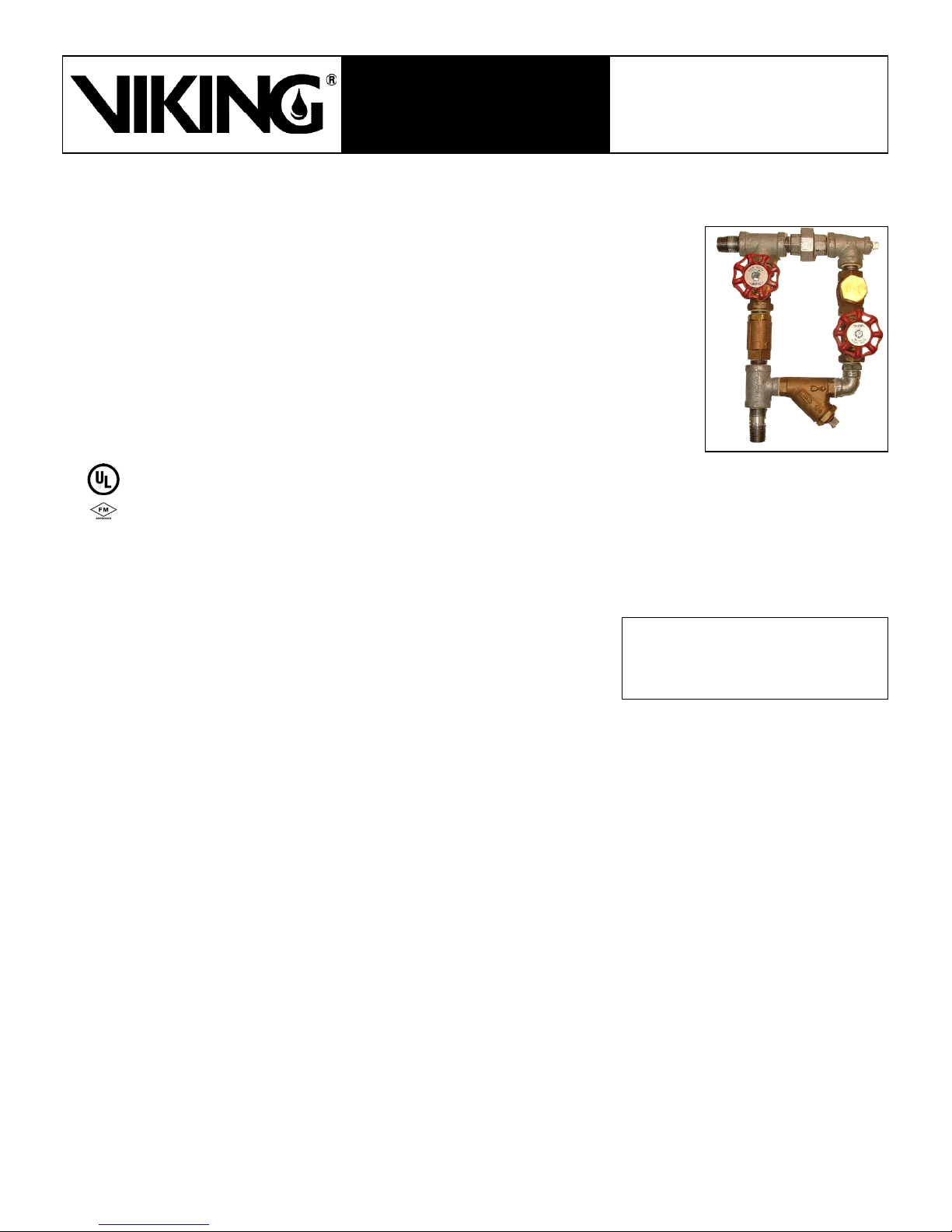
MODEL A-1
1. DESCRIPTION
SPEED CONTROL ASSEMBLY
The Viking Speed Control Assembly provides adjustment of the opening speed of Viking Deluge
Valves, and adjustment of both the opening and closing speed of Viking Flow Control Valves.
Water hammer, which may result from the opening of a deluge valve or opening and closing
of a flow control valve, may be reduced by adjusting opening and/or closing speed. Also, use
of the speed control assembly, along with the Viking Pilot Pressure Regulating Valve, enables
pressure regulation for reducing high water supply (inlet) pressures to lower outlet pressures.
The speed control assembly is factory assembled for easy installation, and is listed for optional
use with Viking Deluge and Flow Control Valves equipped with Conventional Trim. The Viking
Speed Control Assembly is required when a Viking Flow Control Valve is equipped with a Viking
Pilot Pressure Regulating Valve.
2. LISTINGS AND APPROVALS:
UL Listed for use with UL Listed Viking Deluge Valves and Flow Control Valves
equipped with Conventional Trim.
UL Listed as a required component when UL Listed Viking Flow Control Valves are equipped with the Viking Pilot Pressure
Regulating Valve.
FM Approved - Deluge Sprinkler Systems, Preaction Sprinkler Systems, Refrigerated Area Sprinkler Systems, On-Off Multi
Cycle Sprinkler Systems
3. TECHNICAL DATA
Specifications:
Water Working Pressure Rating: For use up to 250 PSI (17.2 bar)
Material Standards:
Refer to Chart in Figure 1.
Ordering Information:
Part Numbers: 08780 (Galvanized) or 11181 (Brass)
Shipping Weight: Approximately 6.8 lbs (3.1 kg)
Available since 1994.
Viking Technical Data may be found on
The Viking Corporation’s Web site at
http://www.vikinggroupinc.com.
The Web site may include a more recent
edition of this Technical Data Page.
4. INSTALLATION
General Installation Instructions:
The Viking Deluge Valve or Flow Control Valve used must be trimmed with Conventional Trim and installed in an area not subject
to freezing temperatures or physical damage. When corrosive atmospheres and/or contaminated water supplies are present, it is
the owner’s responsibility to verify compatibility with the Valve, Trim, Speed Control Assembly, and associated equipment.
For proper operation and approval, the Speed Control Assembly must be installed according to the appropriate Viking Deluge
Valve or Flow Control Valve Trim Chart and Viking schematic drawings for the system being installed. Trim Charts are provided in
the Speed Control Assembly Package.
1. Verify that the Viking Deluge Valve Trim or Flow Control Valve Trim used is Conventional Trim (Refer to Figure 2). If the trim has
been installed, verify that it has been installed according to current trim charts.
2. Verify that the system is out of service and that the Deluge or Flow Control Valve Conventional Trim has been de-pressurized
and properly drained.
3. On valves with trim installed, remove the pipe connecting the priming chamber to the trim by loosening the two unions provided.
4. Remove plastic thread protectors from the Speed Control Assembly.
5. Apply a small amount of pipe joint compound or tape to the external threads of all pipe connections required. Take care not to
allow any compound, tape, or other foreign matter inside any of the nipples or openings of the Speed Control Assembly or other
trim components.
6. Remove the union parts from the pipe removed in step 3 and install them on the 1/2” (15 mm) NPT nipples provided on the
Speed Control Assembly.
7. Install the Speed Control Assembly as shown on the appropriate Viking Trim Chart provided in Figure 2.
Form No. F_091794 16.04.28 Rev 16.1
Replaces page 533a-d, dated January 4, 2010.
(Revised the Replacement Parts list. Updated to ANSI style.)
Page 2 of 5
TECHNICAL DATA
The Viking Corporation, 210 N Industrial Park Drive, Hastings MI 49058
Telephone: 269-945-9501 Technical Services: 877-384-5464 Fax: 269-818-1680 Email: techsvcs@vikingcorp.com
Hydrostatic Test:
CAUTION
When a Pressure Operated Relief Valve (PORV) is installed in the Deluge or Flow Control Valve trim, DO NOT subject
the PORV to a 200 psi (13.8 bar) hydrostatic system test unless the 1/2” trim piping connecting the outlet chamber of
the Deluge or Flow Control Valve to the operating (single ported) end of the PORV is disconnected and plugged during
the test. Remove the plugs and re-connect the piping before placing the system in service.
4-A. PLACING IN SERVICE
A. PROCEDURE FOR DELUGE VALVES:
1. Adjust speed control to the initial setting for deluge valves:
a. Fully OPEN the needle valve controlling flow into the priming chamber. This needle valve is marked “SLOW CLOSE”.
b. Fully CLOSE the needle valve controlling flow out of the priming chamber. (This needle valve is marked “SLOW OPEN”.)
Then partially open it, turning it approximately one and one-half turn counter-clockwise.
2. Place the system in service according to instructions printed in current Technical Data for the Viking Deluge Valve used.
3. Perform Trip Test to test the deluge valve opening speed with initial settings as described in step 1. (Opening the emer-
gency release will trip the system.)
CAUTION
Performing a trip test results in operation of the Deluge Valve. Water will flow into the sprinkler piping and out of any
open sprinklers. Take necessary precautions to prevent damage.
MODEL A-1
SPEED CONTROL ASSEMBLY
a. Observe the time required for the deluge valve to open.
4. Reset the deluge valve according to instructions printed in current Technical Data for the valve used.
5. Adjustment procedure for deluge valves:
a. If the opening speed observed in step 3 was too fast, turn the needle valve marked “SLOW OPEN” clockwise.
NOTE: Needle valves are modified to prevent complete closure. Fully closing the needle valves will not prevent the
Deluge Valve from operating.
b. If the opening speed was too slow, turn the needle valve marked “SLOW OPEN” counter-clockwise.
6. Repeat steps 3 through 5 until the desired operating speed is achieved.
B. PROCEDURE FOR FLOW CONTROL VALVES:
1. Adjust speed control to initial setting for flow control valves:
a. Fully CLOSE BOTH needle valves, then partially open them, turning both approximately one and one-half turns coun-
terclockwise.
2. Place the system in service according to instructions printed in current Technical Data for the Viking Flow Control Valve
used.
3. Perform Trip Test to test the flow control valve operating speed with initial settings as described in step 1.
CAUTION
Performing a trip test results in operation of the Flow Control Valve. Water will flow into the sprinkler piping and out of
any open sprinklers. Take necessary precautions to prevent damage.
a. Observe the time required for the flow control valve to open.
4. Reset the releasing device used to trip the system.
a. Observe the time required for the flow control valve to reset.
5. Adjustment procedure for flow control:
a. If the opening speed observed in step 3 was too fast, turn the needle valve marked “SLOW OPEN” clockwise.
NOTE: Needle valves are modified to prevent complete closure. Fully closing the needle valves will not prevent the
Flow Control Valve from operating.
b. If the opening speed was too slow, turn the needle valve marked “SLOW OPEN” counter-clockwise.
c. If the closing (resetting) speed observed in step 3 was too fast, turn the needle valve marked “SLOW CLOSE” clock-
wise.
d. If the closing (resetting) speed was too slow, turn the needle valve marked “SLOW CLOSE” counter-clockwise.
6. Repeat steps 3 through 5 until the desired operating speed is achieved.
Form No. F_091794 16.04.28 Rev 16.1
 Loading...