

VigoTec VG-X4 Hardware Installation Manual
1/9
Hardware Installation Manual
Support:VG-X4
Overall Size:570×436×88(L×W×H)
Print Size:310×256mm(L×W)
Powered by VigoTec 2019.
Catalogue: 1. Parts list, 2. Installation, 3. Notice
1.Parts list
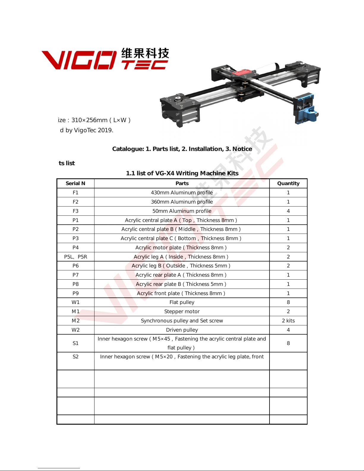
1.1 list of VG-X4 Writing Machine Kits
Serial N Parts Quantity
F1 430mm Aluminum profile 1
F2 360mm Aluminum profile 1
F3 50mm Aluminum profile 4
P1 Acrylic central plate A(Top,Thickness 8mm) 1
P2 Acrylic central plate B(Middle,Thickness 8mm) 1
P3 Acrylic central plate C(Bottom,Thickness 8mm) 1
P4 Acrylic motor plate(Thickness 8mm) 2
P5L、P5R Acrylic leg A(Inside,Thickness 8mm) 2
P6 Acrylic leg B(Outside,Thickness 5mm) 2
P7 Acrylic rear plate A(Thickness 8mm) 1
P8 Acrylic rear plate B(Thickness 5mm) 1
P9 Acrylic front plate(Thickness 8mm) 1
W1 Flat pulley 8
M1 Stepper motor 2
M2 Synchronous pulley and Set screw 2 kits
W2 Driven pulley 4
S1
Inner hexagon screw(M5×45,Fastening the acrylic central plate and
flat pulley)
8
S2 Inner hexagon screw(M5×20,Fastening the acrylic leg plate, front
plate, rear plate and pen control kit/Laser kit)
9
S3 Inner hexagon screw(M5×12,Fastening the acrylic motor, leg and
front plate)
25
N1 Antiskid nut(M5,Fastening the acrylic central plate and flat pulley)
8
N2 Square nut(M5,Fastening the acrylic motor plate and synchronous
belt)
13
N3 L type connector(M5 Nut,Fastening the acrylic front and rear plate)
2
2/9
Serial N Parts Quantity
S4 Set screw(M5,Fastening the acrylic front plate, rear plate and
synchronous belt)
4
N4 Nut column(M5×6,Fastening the acrylic central plate, flat pulley and
pen control kit/Laser kit)
18
S5 Inner hexagon screw(M3×35,Fastening the Driven pulley) 2
S6 Inner hexagon screw(M3×10,Fastening the Stepper motor) 8
N5 Nut(M3,Fastening the Driven pulley on central plate) 2
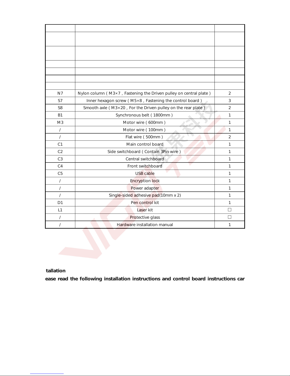
N6 Nylon column(M3×5,Fastening the Driven pulley on central plate)
2
N7 Nylon column(M3×7,Fastening the Driven pulley on central plate)
2
S7 Inner hexagon screw(M5×8,Fastening the control board) 3
S8 Smooth axle(M3×20,For the Driven pulley on the rear plate) 2
B1 Synchronous belt(1800mm) 1
M3 Motor wire(600mm) 1
/ Motor wire(100mm) 1
/ Flat wire(500mm) 2
C1 Main control board 1
C2 Side switchboard(Contain 3Pin wire) 1
C3 Central switchboard 1
C4 Front switchboard 1
C5 USB cable 1
/ Encryption lock 1
/ Power adapter 1
/ Single-sided adhesive pad(10mm x 2) 1
D1 Pen control kit 1
L1 Laser kit
□
/ Protective glass
□
/ Hardware installation manual 1
2.Installation
Please read the following installation instructions and control board instructions carefully,
and pay attention to the sequence of installation. The shape of parts in the following installation
instructions is only as a sigh. Please refer to the shape of the actual parts purchased. Please pay
attention to the clearance between the pulley and the profile in center part, and also it should be
able to slide smoothly in both directions. Please pay attention to the position of the synchronous
wheels on the stepper motors.
2.1 Installation instructions
3/9
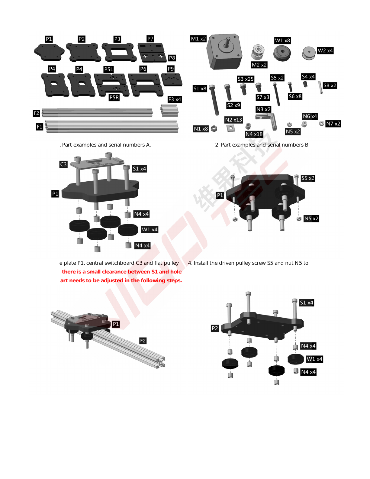
1. Part examples and serial numbers A。 2. Part examples and serial numbers B。
3. Install the plate P1, central switchboard C3 and flat pulley
W1.Because there is a small clearance between S1 and hole
of P1, this part needs to be adjusted in the following steps.
4. Install the driven pulley screw S5 and nut N5 to the plate P1.
5. Slide the profile F2 into the central plate P1. As described
above, please adjust the S1,N4 and pulley W1 in step 3
repeatedly to ensure no clearance between pulley W1 and
profile F2. At the same time, it should slide smoothly.
6. Install the central plate P2 and flat pulley W1. Because there
is a small clearance between S1 and hole of P2, this part
needs to be adjusted in the following steps.
 Loading...