

VigoTec VG-L7 Hardware Installation Manual
Hardware Installation Manual
Support:VG-L7
Overall Size:445×401×128mm(L×W×H)
Print Size:330×190mm(L×W)
Powered by VigoTec 2019.s
CATALOGUE
1. PARTS LIST .................................................................................................................................................................... 1
2. INSTALLATION ............................................................................................................................................................. 1
3. CONTROL-BOARD AND LASER................................................................................................................................ 2
4. NOTICE AND FAQ ........................................................................................................................................................ 3
5. UPDATE .......................................................................................................................................................................... 4
6. WARNING ...................................................................................................................................................................... 4
1. Parts list
Parts list of VG-L7 Kits
Serial N Parts Quantity
F1 Frame Part A (Lower part) 1
F2 Frame Part B (Upper part) 1
F3 Laser 1
/ Stepper Motor wire 2
/ Laser wire 1
/ Side to Main control board wire 1
/ USB cable 1
/ Power supply 1
/ Protective glass 1
/ Hardware installation manual 1
VG-L7 Tools
Serial N Parts Quantity
N1 M5 Nut (Frame Fixed) 4
N2 M3x12 Screw (Laser Fixed) 2
N3 M3 Nut (Laser Fixed) 2
2. Installation
Please read the following installation instructions and control board instructions carefully, and pay
1/4
attention to the sequence of installation. The shape of parts in the following installation instructions is
only as a sigh. Please refer to the shape of the actual parts purchased.
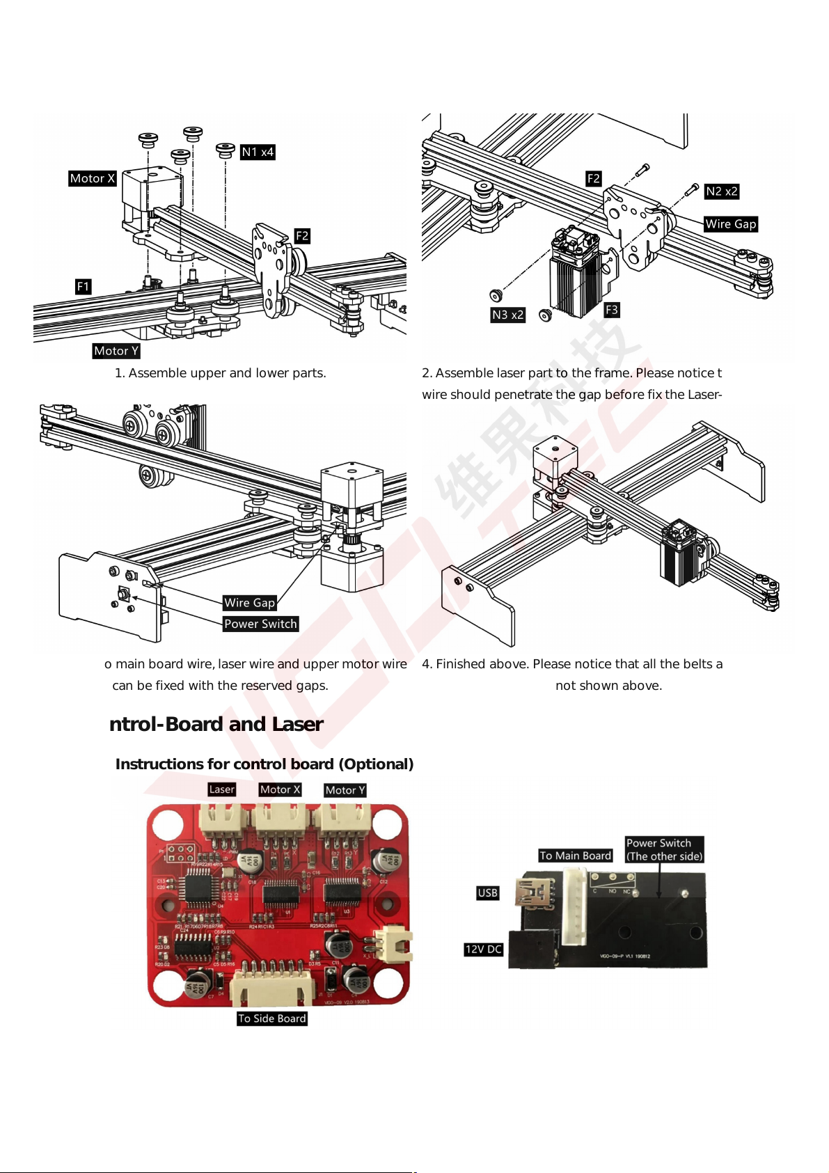
1. Assemble upper and lower parts. 2. Assemble laser part to the frame. Please notice that the laser
wire should penetrate the gap before fix the Laser-Module(F3).
3. The side to main board wire, laser wire and upper motor wire
can be fixed with the reserved gaps.
3. Control-Board and Laser
3.1 Instructions for control board (Optional)
Main Control Board(Left), Side Board(Right)
4. Finished above. Please notice that all the belts and wires are
not shown above.
2/4
 Loading...