

Page 1
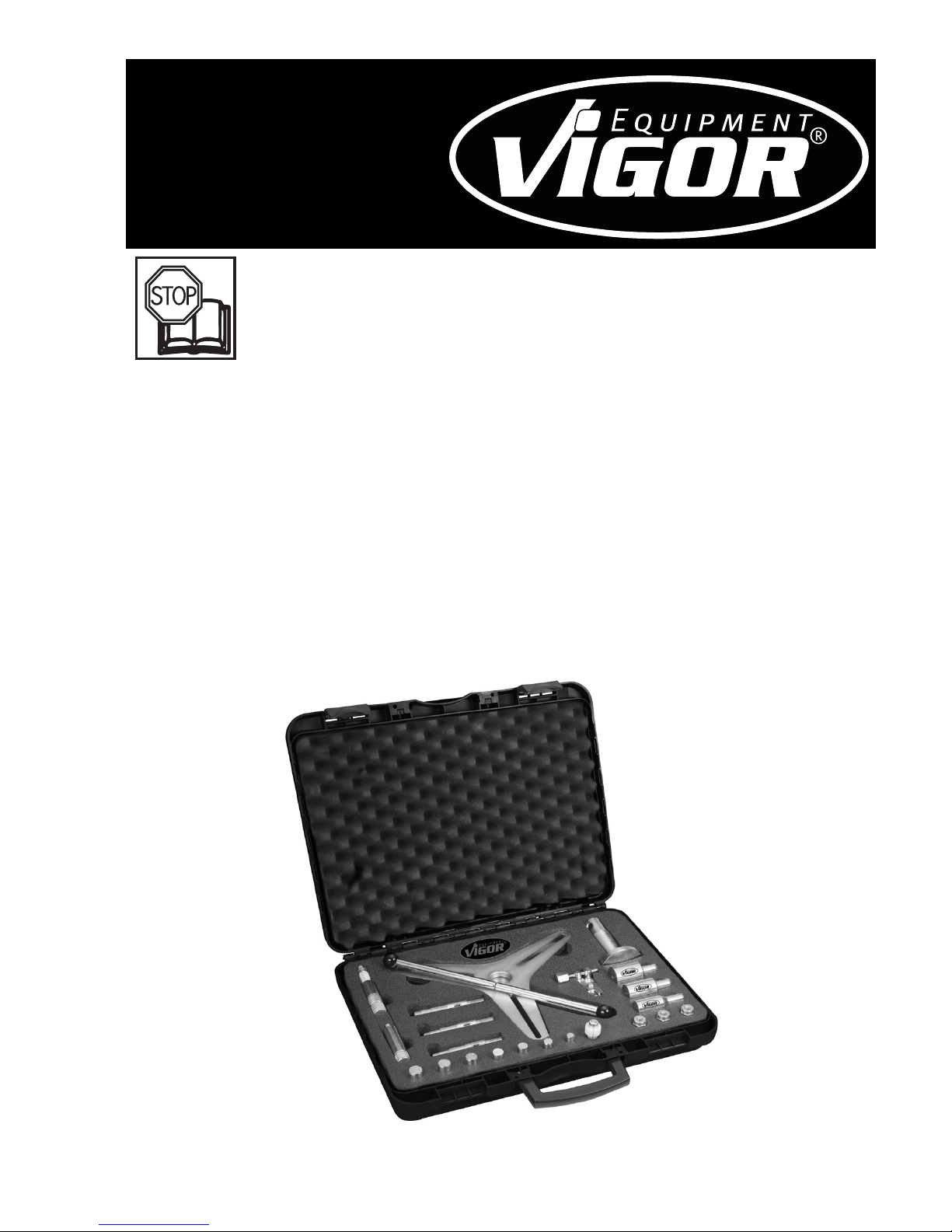
Operating Instructions
SAC Clutch Alignment
Tool Set
V 2306
Page 2

1. For your Information 8
2. For your Safety 9
2.1
Owner’s Liability
9
2.2 Appropriate
Use
9
2.3
Dangers emanating from the Tool
/
Personal Protective Equipment 9
3. Design and Function 10 ... 12
3.1
Technical Data / Included in Delivery
10
3.2 O
ptional Accessories
10
3.3 Process and Functional Description 11 ... 12
4. Maintenance and Cleaning 12
4.1 Maintenance and Cleaning 12
4.2
Spare Parts
12
5.
Storage
12
6.
Disposal
12
2
ViGOR GmbH • } 10 04 61 • D-42804 Remscheid • Germany • [ +49 (0) 21 91 / 97 95
\
+49 (0) 21 91 / 97 96 00 • ^ vigor-equipment.com • ] [email protected]
Ursprungsprache deutsch – original language: German
Page 3
8
1 For Your Information
1.1. General Information
Please make sure that the user of this ViGOR tool carefully reads these operating instructions
and fully understands all information given before it is used.
• For effective use of the ViGOR Clutch Alignment Tool as intended, it is essential that all safety
and other infor mation in these operating instructions is adhered to.
• For this reason, always keep these operating instructions together with your ViGOR Clutch
Alignment Tool.
• This ViGOR Clutch Alignment Tool has been designed exclusively for specific applications.
ViGOR emphasizes that any modification to the ViGOR Clutch Alignment Tool and/or use on
an application not detailed to its intended application are strictly forbidden.
•
ViGOR will not be liable for any injuries to persons or damage to property originating from
improper application, misuse of the ViGOR Clutch Alignment Tool or a disregard of the safety
instructions.
• Furthermore, the general safety regulations and regulations for the prevention of
accidents valid for the application area of this tool must be observed and respected.
1.2. Explanation of Symbols
ATTENTION : Please pay attention to these symbols!
Read the operating instructions!
The owner of this tool is obliged to observe the operating instructions and should
ensure all users of this ViGOR Clutch Alignment Tool use it according to the information given in this manual.
NOTICE!
This symbol marks advice which is helpful when using the ViGOR Clutch Tool.
CAUTION!
This symbol marks important specifications, dangerous conditions, safety risks and
safety advice.
ATTENTION!
This symbol marks advice which if disregarded results in damage, malfunction
and/or functional failure of the ViGOR Clutch Tool.
Page 4
9
2 For Your Safety
2.1. Owner’s Liability
This ViGOR Clutch Alignment Tool set was developed and manu factured according to
the technical norms and standards valid at the time and is considered to be operation-
ally reliable. Nevertheless, the ViGOR Clutch Alignment Tool can present a danger
when it is not used as intended or in an inappropriate way by non-qualified personnel. Please
make sure that any person using this ViGOR Clutch Alignment Tool or carrying out maintenance
work carefully reads these operating instructions and fully understands all information given,
before using the ViGOR Clutch Tool.
• Keep the operating instructions together with the ViGOR Clutch Alignment Tool at all times.
• Any modification of the ViGOR Clutch Alignment Tool is strictly forbidden.
• All security advices, warning and operation notices on the ViGOR Clutch Alignment Tool have
to be kept legible. Replace all damaged labels or stickers.
• All indications concerning setting values and setting ranges have to be observed.
• Only use accessories recommended or sold by the manufacturer in order to avoid damage
to the unit, or injury to personnel.
2.2. Appropriate Use
Operational reliability can only be ensured, if the ViGOR Clutch Alignment Tool is used
as intended and in compliance with the indications given in the operating instructions.
In addition to the safety advice given in these operating instructions, the general safety
regulations, regulations for the prevention of accidents and regulations for environmental protection being valid for the application area of this ViGOR Clutch Alignment Tool have to be
observed and respected.
Always ensure that tools are used, inspected and maintained in com pliance with the respective local, state, national or federal regu lations
• The ViGOR Clutch Alignment Tool must only be used if it is in good working order.
• Any deviation from the intended use and/or any misapplication of the ViGOR Clutch
Alignment Tool is not allowed and will be considered as improper use.
• Any claims against the manufacturer and/or its authorized agents because of damage
caused by improper use of the ViGOR Clutch Alignment Tool will be void.
• Any personal injury or material losses caused by improper use are the sole responsibility of the
user.
2.3.
Dangers emanating from the tool /
Personal Protective Equipment
Before each use, check the ViGOR Clutch Alignment Tool for full functional efficiency.
Do not use the ViGOR Clutch Alignment Tool if its functional efficiency cannot be
ensured or if damage is detected. If the ViGOR Clutch Alignment Tool is used, although
it is not in full working order, you risk severe injuries to persons and damage to property.
• Full functional efficiency is given when:
- the ViGOR Clutch Alignment Tool smooth-running,
- the ViGOR Clutch Alignment Tool does not present any damage.
• Any service or repair work must be carried out by qualified personnel only. In order to guar-
antee long term operational safety, only original spare parts must be used.
• For safety reasons any modification of ViGOR Clutch Tools is strictly forbidden. Any modifica-
tion of the ViGOR Clutch Alignment Tool will result in immediate exclusion from warranty and
liability.
• When operating the VIGOR Clutch Alignment Tool, do not reach into the device. Otherwise
you risk serious injury.
• When operating the ViGOR Clutch Alignment Tool, it is necessary to wear safety glasses and
proper-fitting protective clothing.
Page 5
10
3 Design and Function
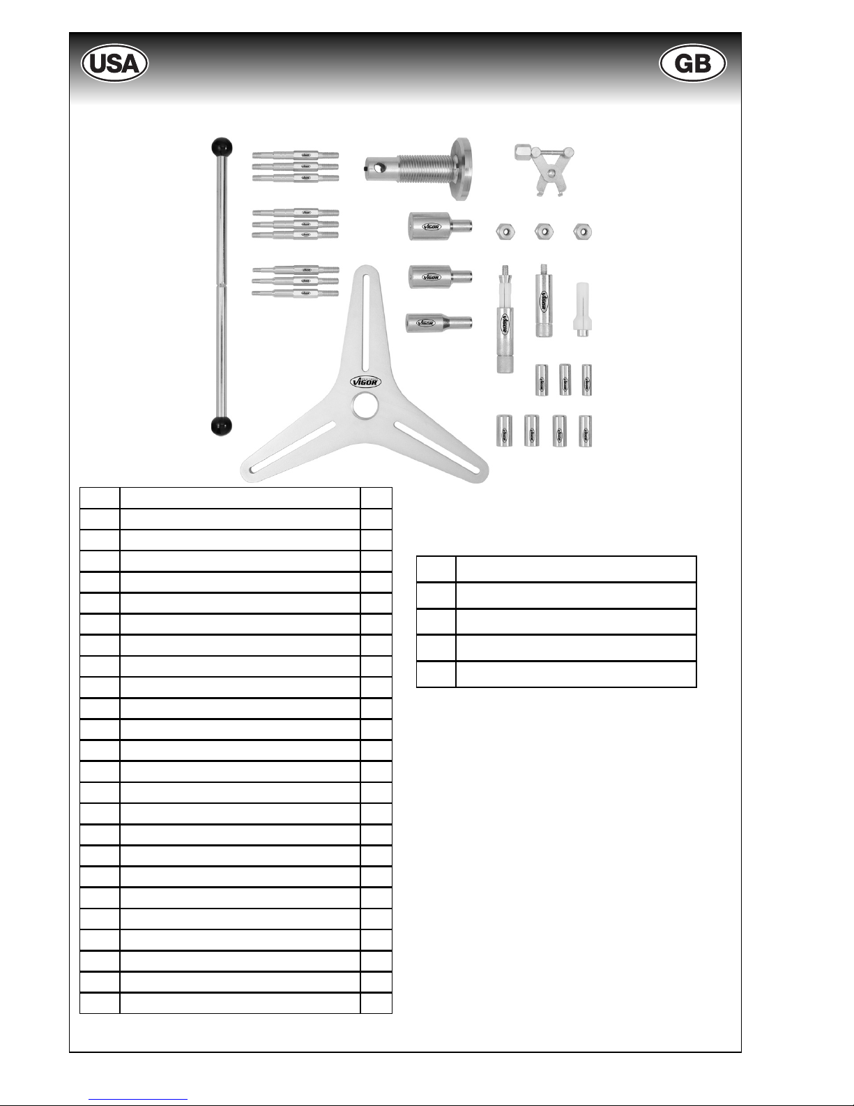
3.1. Technical Data / Included in Delivery
3.2 Optional Accessories
V2308
Expansion set for SAC Clutch
Alignment Tool Set, consisting of:
1x
Pressure plate (4-hole pitch)
1x
Fixing nut
1x
Fixing screw M6
1x
Fixing screw M7
1x
Fixing screw M8
a -
Pressure piece (3-hole pitch)
1x
b -
Pressure spindle
1x
c -
Operation lever
1x
d -
Resetting tool
1x
e -
Fixing nut
3x
f -
15x23
Centring pin
1x
g -
15x28
Centring pin
1x
h -
15x34
Centring pin
1x
i -
Fixing screw
M6
3x
j -
Fixing screw
M7
3x
k -
Fixing screw
M8
3x
l -
Centring head
12mm
1x
m -
Centring head
14mm
1x
n -
Centring head
15mm
1x
o -
Centring head
16mm
1x
p -
Centring head
17mm
1x
q -
Centring head
18mm
1x
r -
Centring head
19mm
1x
s -
Centring head adapter
1x
t -
Basic spindle with cone operation
1x
u -
Basic clamping nut
1x
v -
Basic centring sleeve
1x
w -
Clamping cone
1x
x -
Clamping cone
1x
y -
Extracting screw
1x
a
b
c
d
e
f
g
h
i
j
k
lmn
opq
t
r
v
u
s
y
x
w
Page 6
11
3 Design and Function
3.3. Process and Functional Description
When working please make sure to observe the instructions of the car manufacturer!
This operation instruction is provided as a guide only. Always make sure that you have a copy
of the appropriate vehicle manufacturer‘s service instructions, or another appropriate manual
that provides the correct information needed to correctly execute the work.
• Gearbox removing, loosening and removal of the necessary components.
• Clutch removal
• Optical and manual inspection of the flywheel for wear (grooves, damages due to high
temperatures, etc.)
• Flywheel replacement, if necessary
Installation:
• For the exact fixation of the clutch disc, choose the corresponding centring pin from the tool set.
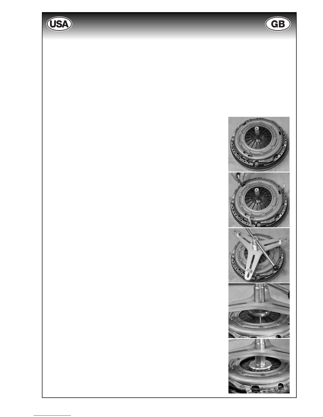
• Insert clutch disc with the centring pin (illustration 1).
• For installation of the clutch pressure plate, choose the corresponding fixing screws (please consider the thread size M6/M7/
M8).
• When working on a current SAC clutch, insert 3 fixing screws (with
the short thread end) at a distance of 120° from one another and
fix them fingertight into the threads of the flywheel. When working on e.g. MERCEDES-BENZ type 169, insert 4 fixing screws at at
distance of 90° from one another (illustr. 2).
•
Choose the corresponding pressure piece with 3-hole pitch or
4-hole pitch.
• Use the operation lever to screw the pressure spindle into the
pressure piece and relieve the diaphragm spring.
• Place the pressure piece, the operation lever and the pressure
spindle onto the clutch pressure plate and fix them snugly with
the fixing screws (illustr. 3).
• Turn the pressure spindle of the pressure piece until the diaphragm spring reaches the limit stop (clutch pressure plate fits
seamlessly on the flywh
eel / illustr. 4 - 5).
• Insert and tighten the fixing screws of the clutch pressure plate
into the thread holes of the flywheel.
• Turn the pressure spindle of the pressure piece anticlockwise to
relieve the diaphragm spring.
• When the diaphragm spring is completely relieved, remove the
fixing screws, the pressure piece and the pressure spindle.
• Insert the remaining fastening screws and tighten all screws
down to the specified torque (Please follow the instructions of the
manufacturer).
• Remove the centring pin with the aid of fthe supplied extracting
screw, if necessary.
Caution: Instruction implies usage of the optional accessory
V2308.
Removal:
• For the removal of the SAC clutch, follow the instructions of the
installation in reverse order. Usage of the centring tools is not necessary.
Fig. 2
Fig. 3
Fig. 1
Fig. 4
Fig. 5
Page 7

12
4.1 Maintenance and Cleaning
• Always keep the VIGOR Clutch Alignment Tool Set clean.
•
Do not use degreasing agents or water in order to avoid corrosion
• For questions and spare parts orders, please indicate the article number of the tool set.
•
Inspection and repair may only be carried out by qualified personnel.
For:
• Warranty
• Maintenance and repair
please contact us: [email protected].
4.2 Spare Parts
• Only use original spare parts of the manufacturer.
•
Unsuitable or defective spare parts may cause damage, malfunction or the tool’s total failure.
•
When using spare parts that are not approved, all warranty claims, service claims, claims
for compensation and liability claims against the manufacturer or its agents, distributors and
sales representatives will be void.
The ViGOR Clutch Alignment Tool must be stored according following conditions:
• Do not store the ViGOR Clutch Alignment Tool outdoors.
•
Store the
ViGOR Clutch Alig
nment Tool in a dry and dust-free place.
• Do not expose the ViGOR Clutch Alignment Tool to liquids or aggressive substances.
•
Storage temperature: -10° up to +45°C
•
Relative air humidity: max. 60%
• For disposal, clean ViGOR Clutch Alignment Tool and disassemble it according to the regulations for work safety and environmental protection. Components can be recycled.
6 Disposal
5 Storage
V 2306 I. 08.2011/ ∞ be/330
4 Maintenance and Cleaning
3 Design and Function
Repositioning:
When operating the new clutch disc with a used clutch pressure plate it is necessary to reset
the adjusting ring of the clutch pressure plate.
• Position the pressure piece with the pressure spindle on the fixing screws and tighten.
• Now use the resetting tool.
•
With the aid of the pressure spindle, press the diaphragm spring of the clutch pressure pressure plate until the adjusting ring moves to the right.
• Resposition the adjusting ring by turning the resetting tool to the left.
•
Do not exert force on the adjusting ring when applying the resetting tool.
•
Turn back the pressure spindle. Remove the pressure piece, the pressure spindle, the resetting tool and the fixing screws.
•
For the installation see instruction on page 11.
 Loading...