

Page 1

Betriebsanleitung
Batterie-/ Ladesystemtester mit Drucker
Operating Instructions
Battery / Charging/ Starting System
Analyzer / Printer
Mode d’emploi
Testeur de batterie et de Circuit de
charge / imprimer
ViGOR 1922
V 1922 BA
Page 2
ViGOR GmbH • } 10 04 6
D-42804 Remscheid • Germany
[
+49 (0) 21 91 / 97 95 •
\
+49 (0) 21 91 / 97 96 00 •
]
^
vigor-equipment.com
................... 3 ... 17
..................... 19 ... 33
..................... 35 ... 50
Page 3
3
1 Zu Ihrer Information
WICHTIG:
1. Zum Testen von 6 und 12 Volt Batterien sowie von 12
und 24 Volt Ladesystemen.
2. Zugelassene Betriebstemperatur 0 °C (32° F) bis
50 °C (122° F) (Umgebungstemperatur)
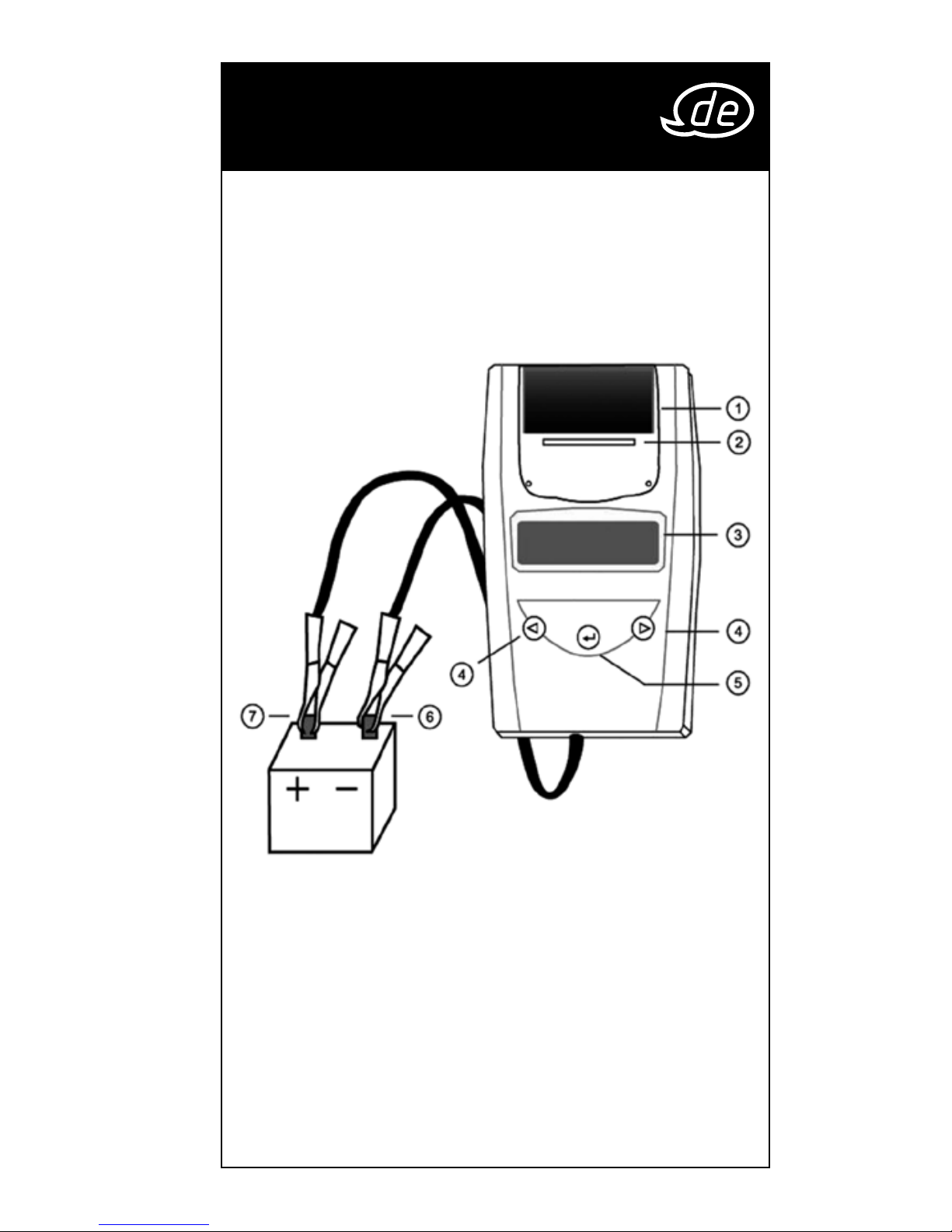
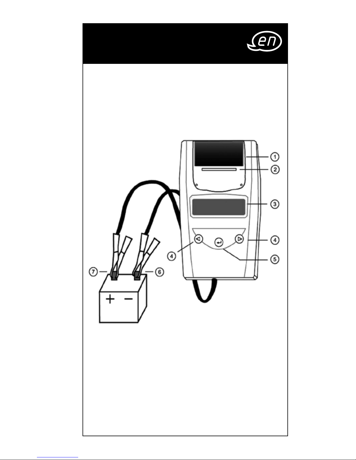
1. Klarsicht Abdeckung
2. Druckerpapier
3. LCD Display
4. Auf-/Abwärts Knöpfe
5. ENTER: Auswahl / Bestätigung
6. Negative Polklemme (Schwarz -)
7. Positive Polklemme (Rot +)
Page 4

4
2 Zu Ihrer Sicherheit
ACHTUNG:
1. Das Arbeiten in der Nähe einer Batterie ist gefährlich.
Im Betrieb befindliche Batterien erzeugen explosive
Gase. Es ist daher äußerst wichtig, dass Sie, um
kein Risiko einzugehen, vor jeder Benutzung des
Testgeräts die Anweisungen sorgfältig lesen.
2. Folgen Sie den Anweisungen, um die Gefahr
einer Batterieexplosion zu verringern, und lesen Sie
Hinweise der Hersteller der Batterie und der in der
Nähe der Batterie benutzten Ausrüstungen. Achten
Sie unbedingt auf die am Gerät befindlichen
Sicherheitsmarkierungen.
3. Setzen Sie das Testgerät weder Regen noch Schnee
aus.
MASSNAHMEN ZUR PERSÖNLICHEN SICHERHEIT:
1. Beim Arbeiten mit einer Batterie sollte immer eine
Person in Ihrer Nähe sein um Hilfe leisten zu können.
2. Halten Sie viel frisches Wasser und Seife bereit, für
den Fall, dass Ihre Haut, Kleidung, oder Augen mit
Batteriesäure in Berührung kommen.
3. Arbeiten Sie mit Schutzbrille und Schutzkleidung.
4. Waschen Sie Haut oder Kleidung, die mit Batteriesäure
in Kontakt kommt, sofort mit Wasser und Seife. Gerät
Säure in die Augen, spülen Sie diese sofort mindestens
zehn Minuten lang mit kaltem, fließendem Wasser
und begeben Sie sich in ärztliche Behandlung.
5. Rauchen Sie NIEMALS und vermeiden Sie Funken oder
Flammen in der Nähe einer Batterie oder Maschine.
6. Achten Sie sorgfältig darauf, dass kein Metallwerkzeug
auf die Batterie fällt. Dies kann Funken erzeugen, die
Batterie oder andere Teile kurzschließen und zu einer
Explosion führen.
7. Tragen Sie beim Arbeiten mit der Batterie keine Ringe,
Armbänder, Halsketten, Uhren etc. Ein möglicher
Kurzschluss kann Gegenstände schmelzen und zu
starken Verbrennungen führen.
Page 5

5
3 Aufbau und Funktion
Vor Inbetriebnahme:
1. Sorgen Sie beim Test für gute Lüftung in der
Umgebung der Batterie.
2. Säubern Sie die Batteriepole. Korrosion darf nicht
mit Augen in Berührung kommen.
3. Suchen Sie nach Rissen oder Brüchen im Gehäuse.
Eine beschädigte Batterie darf nicht getestet
werden.
4. Füllen Sie bei nicht wartungsfreien Batterien destil
liertes Wasser in jede Zelle, bis die Batteriesäure das
vom Hersteller angegebene Maß erreicht. So wird
Gasüberschuss entfernt. Vermeiden Sie Überlaufen.
5. Lösen Sie den Erdanschluss von der Batterie, falls
diese zum Testen aus einem Fahrzeug entfernt wird.
Schalten Sie alle Geräte im Fahrzeug aus, um einen
Funkensprung unmöglich zu machen.
Page 6
6
3 Aufbau und Funktion
Inbetriebnahme:
Batterietest
1. Schalten Sie vor dem Batterietest an einem
Fahrzeug die Zündung und alle Verbraucher aus.
Schließen Sie Türen und Kofferraum.
2. In der Batteriekammer des Testgerätes müssen
sich 4 Stück 1.5V Batterien befinden. Sollten diese
Batterien leer sein, erscheint im Gerätedisplay
die Meldung “ERSETZEN SIE DIE INTERNE BATTERIE”
oder “ENERGIE NIEDRIG”. Ersetzen Sie in diesem
Falle die 4 Stück 1.5V Batterien vor dem Test
der Fahrzeugbatterie. Oxydierende Batterien
werden wegen deren anfänglicher 1,7-VoltAusgangsleistung nicht empfohlen.
Bedenken Sie, dass nichts auf der Anzeige zu
sehen sein wird, solange der Tester nicht mit dem
Batterieträger verbunden ist.
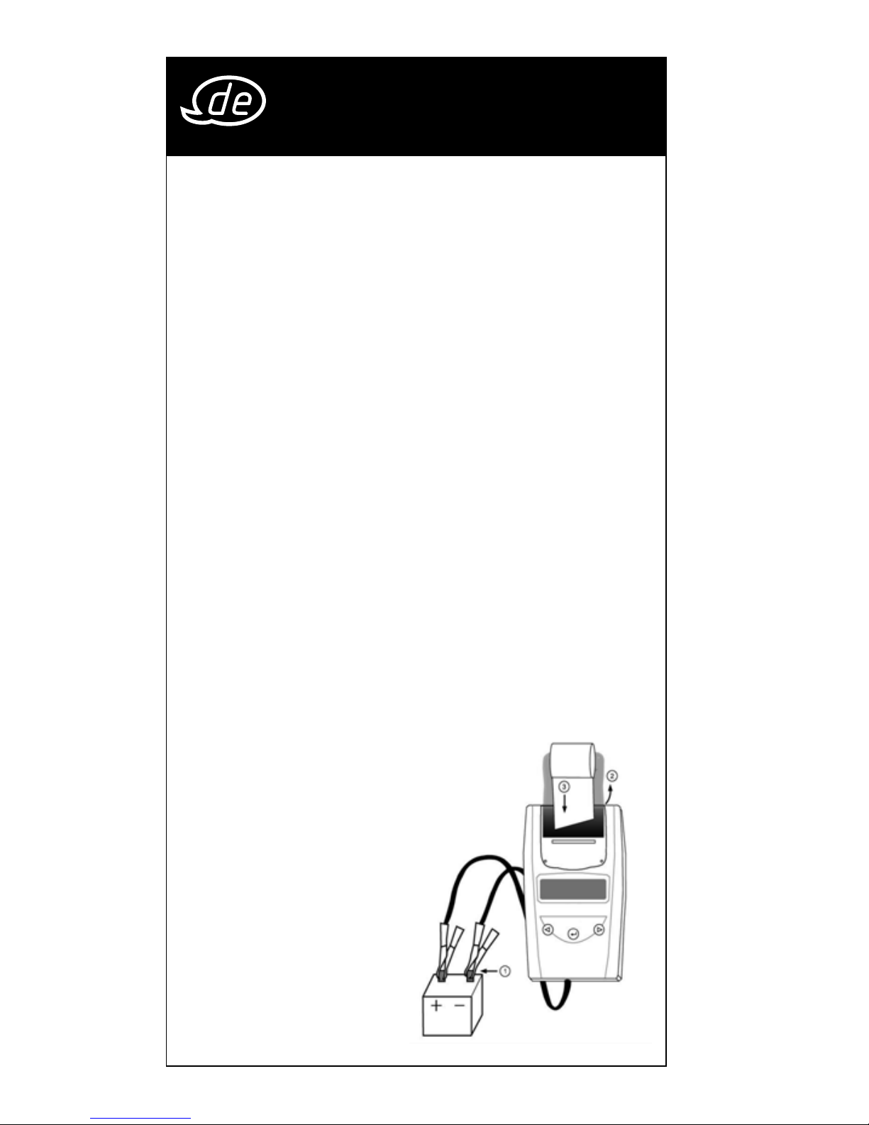
3. Klemmen Sie das schwarze Kabel an den nega
tiven Pol der Fahrzeugbatterie und das rote Kabel
an den positiven Pol der Fahrzeugbatterie. Nur
an das Bleiteil der Klemme anklemmen. Das
Anklemmen an das Eisenteil der Klemme führt zu
falschen Prüfresultaten.
4. Papier laden: Öffnen
Sie den Deckel. Setzen
Sie Papier ein, so daß
das Papier automa
tisch in den Drucker
läuft.
5. Ersatzrollen erhal
ten Sie unter der
Materialnummer V1923
als Zubehör.
Page 7
7
3 Aufbau und Funktion
Austausch der Papierrolle?
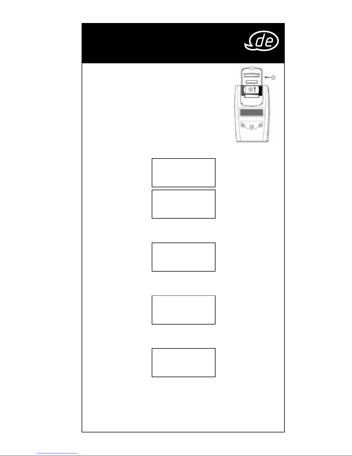
Schritt 1: Öffnen Sie das Klarsichtfach.
Schritt 2: Führen Sie das Papier langsam
und gerade von der Rolle in
den Führungsschacht.
1. Auf dem Bildschirm
erscheinen die folgenden Meldungen:
SYSTEM TESTER
BATTERIE TEST |} 8
××.×× V
* Drücken Sie
| / }
zur Sprachwahl oder Systemtest
* Drücken Sie “Enter” für Batterietest.
SYSTEM TEST
|} 8
××.×× V
* Drücken Sie
| / }
für Batteriestest oder Sprachwahl
* Drücken Sie “Enter” für Systemtest
LANGUAGE |} 8
SELECT
* Drücken Sie “Enter” zur Sprachwahl.
* Drücken Sie
| / }
für Batteriestest oder Systemtest
LANGUAGE
|} 8
GERMAN
* Drücken Sie
| / }
zur Sprachwahl.
(Englisch, Französisch, Deutsch, Spanisch, Italienisch,
Portugiesisch, Japanisch.)
* Drücken Sie “Enter” zur Bestätigung und zurück zum
Batterietest.
Page 8
8
3 Aufbau und Funktion
2. Drücken Sie die | / } Taste, um den Batterietest
auszuwählen. Drücken Sie «ENTER». Beispiel:
3. Wählen Sie mir der
| / }
Taste, den Batterietyp:
Batterietyp |} 8
AGM Platte
a FLUESSIG-BATT b AGM PLATTE
c AGM SPIRALE d VRLA/GEL
Bestätigen Sie die Wahl mit «ENTER».
4. Wählen Sie mit der
| / }
Taste, die Prüfnorm:
Norm auswählen
|} 8
SAE
SAE, EN, IEC, DIN oder JIS (Angaben auf der Batterie)
Bestätigen Sie mit «ENTER».
5. Wählen Sie die Batteriekapazität in CCA mit
der
| / }
Taste:
Kapazitaet CCA |} 8
xxxx SAE
• SAE: 40~2000 • EN: 40~2100
• IEC: 30~1500 • DIN: 25~1300
• JIS: Durch Batterie Art Zahl
Zum Start des Tests, drücken Sie «ENTER».
6. Testen Sie die Batterie 5-7 Sekunden lang.
TEST Laeuft
7. Wählen Sie mit der
| / }
Taste, eine der
Optionen, Batterie voll geladen:
Ist die Batterie |} 8
aufgeladen? Ja
JA oder NEIN. Bestätigen Sie mit «ENTER».
Page 9

9
3 Aufbau und Funktion
8.
Nach dem Ende des Tests zeigt das LED Display
die aktuelle Voltangabe und CCA an oder %. Die
Toleranz bei der Voltmessung liegt bei +/- 0,05 V
und bei der Kaltstrommessung bei +/- 5% CCA.
(Zum Wählen zwischen SOH (BATT. ZUSTAND) oder
SOC (LADEZUSTAND) drücken Sie auf die Taste
| / }
.
Eines der sechs Ergebnisse wird angezeigt:
GUT & BESTANDEN
xx.xx V xxxx SAE
GUT & BESTANDEN:
Die Batterie ist okay und in der
Lage Ladung zu halten.
GUT & Aufladen
xx.xx V xxxx SAE
GUT & AUFLADEN:
Die Batterie okay, muss jedoch
aufgeladen werden.
LADEN & PRÜFEN
xx.xx V xxxx SAE
LADEN & PRUEFEN:
Die Batterie ist entladen, der
Zustand kann nicht vor einem
Aufladen bestimmt werden.
Laden Sie die Batterie & testen
Sie erneut.
DEFEKT & ERSETZEN
xx.xx V xxxx SAE
DEFEKT/ERSETZEN:
Die Batterie kann keine Ladung
halten. Sie muss sofort ersetzt
werden.
ZELLE DEFEKT
xx.xx V xxxx SAE
ZELLE DEFEKT:
Zumindest eine Batteriezelle ist
kurzgeschlossen. Ein sofortiger
Austausch ist nötig.
LOAD ERROR
BELASTUNGSFEHLER:
Die getestete Batterie ist größer
als 2000
CCA oder 200 AH oder
die Klemmen sind nicht korrekt
angeschlossen. Bitte laden Sie die Batterie voll
ständig auf und testen Sie sie erneut. Bei gleiche
m Ergebnis sollte die Batterie unverzüglich ausge
tauscht werden.
Page 10
10
9. Wählen Sie mit der
| / }
Taste, ob das Ergebnis
ausgedruckt werden soll: JA
ERGEBNIS DRUCKEN?|} 8
JA
oder NEIN. Bestätigen Sie mit «ENTER».
* Ausdrucken des 24 V-System-Tests:
24 V SYSTEMTEST
DRUCKEN? |} 8
JA
Der Drucker funktioniert nicht für das Ausdrucken
der Systemtests der 24-Volt-Batterien. Das
24-V-Systemtestresultat wird aufgezeichnet, bis
Sie eine 12-V-Batterie anschließen, wonach der
rechte Bildschirm eingeblendet wird. Wählen
Sie “JA” und drücken Sie auf die Eingabetaste
(ENTER), um das Resultat auszudrucken. Danach
die Klemmen abtrennen. Nach dem Abtrennen
der Klemmen wird der Bildschirm erneut eingeblendet. Wählen Sie “NEIN” und drücken Sie auf
die Eingabetaste (ENTER), um zum Hauptmenü
zurückzukehren.
10. Drücken Sie auf «ENTER» gehen Sie
zurück zu Schritt 5 oder entfernen Sie die
Testklemmen von der Batterie um das Gerät
auszuschalten.
3 Aufbau und Funktion
Page 11
11
SYSTEMTEST Beispiel:
1. Wenn Sie auf «ENTER»
SYSTEM TEST
xx.xx V
drücken, erscheint
folgender Bildschirm:
2. Schalten Sie alle Verbraucher
Verbraucher AUS
MOTOR STARTEN
des Fahrzeugs, wie etwa Licht,
Klimaanlage, Radio usw. aus
bevor Sie das Gerät
einschalten.
3. Nach dem Start erscheint eins der beiden Resultate
mit dem aktuell gelesenen Wert.
ANLASS-SPANNUNG NORMAL
Anlass-Spannung
xx.xx V Normal
Das System zeigt ein norma-
les Ergebnis. Drücken Sie auf
«ENTER», um den Ladetest
auszuführen.
ANLASS-SPANNUNG LOW
Anlass-Spannung
xx.xx V Low
Die Startspannung liegt unter
normalen Werten, Suchen Sie
nach möglichen Fehlern, auf
vom Hersteller empfohlene Weise.
ANLASS-SPANNUNG
NICHTS ENTDECKT
Anlass-Spannung
Nichts Entdeckt
Die Startspannung nicht
entdeckt.
4. Drücken Sie bei normaler
DRÜCKEN SIE ENTER
Für Ladungstest
Startspannung auf «ENTER»,
um den Aufladetest zu
starten.
5. Wenn Sie auf «ENTER»
Alle Verbraucher
Ausschalten
drücken, erscheint der
folgende Bildschirm.
3 Aufbau und Funktion
Page 12
12
6. Nach dem Drücken der «ENTER» Taste erscheint eins
der folgenden drei Resultate zusammen mit dem
aktuell gelesenen Wert.
LADESPANNUNG OHNE BELASTUNG
Die Lichtmaschine produziert
Leerlauf-Spannung
xx.xx V Niedrig
nicht genügend Strom für die
Batterie. Prüfen Sie den
Keilriemen, um sicherzustellen das die Lichtmaschine
bei laufendem Motor arbeitet. Ersetzen Sie eventu
ell rutschende oder gebrochene Riemen und
testen Sie erneut. Prüfen Sie die Verbindung zwi
schen Lichtmaschine und Batterie. Säubern bzw.
ersetzen Sie korrodierte oder lose Kabel und testen
Sie erneut. Sind die Riemen und Kabel in gutem
Zustand, ersetzen Sie die Lichtmaschine.
LADESYSTEM NORMAL BEI TEST OHNE BELASTUNG
Das System zeigt normale
Leerlauf-Spannung
xx.xx V Normal
Ausgangswerte der Lichtmaschine an. Es gibt kein
Problem.
HOHE LADESPANNUNG BEI TEST OHNE BELASTUNG
Die Ausgangsspannung mit der
Leerlauf-Spannung
xx.xx V Hoch
die Lichtmaschine die Batterie
versorgt, liegt über dem norma
len Niveau. Suchen Sie nach einer losen Verbindung
oder einer fehlerhafteren Massebindung. Wenn
alles in ordnungsgemäßem Zustand ist, tauschen
Sie den Regler aus. Ist der Regler nicht einzeln zu
tauschen, muss die Lichtmaschine ausgetauscht
werden. Das normale obere Limit eines normalen
Fahrzeugreglers liegt bei 14.7 Volt +/- 0.05. Prüfen
Sie die Limitangabe des Herstellers, sie variiert je
nach Fahrzeugtyp und Hersteller.
3 Aufbau und Funktion
Page 13
13
7.
Drücken Sie als nächstes auf
Verbraucher ein
Enter drücken
«ENTER», um ein Ladesystem
mit Belastungen zu testen.
Schalten Sie die Lüftung (Hitze), Fernscheinwerfer,
und heizbare Heckscheibe ein. Benutzen Sie keine
zyklischen Belastungen, etwa eine Klimaanlage
oder Scheibenwischer.
8. Beim Testen älterer Dieselmaschinen, bringen Sie die
Maschine 15 Sekunden lang auf 2500 rpm. Es
erscheint folgender Bildschirm:
Drehzahl auf
2500/Min 15 SEK
9. Drücken Sie auf «ENTER», um zu prüfen, wie viel
Brummspannung vom Ladesystem zum Akku
gehen. Eins der zwei folgenden Testergebnisse
wird zusammen mit dem aktuellen Testergebnis
angezeigt.
DIODEN TEST NORMAL
DIODEN TEST
xx.xx V Normal
Die Dioden der Lichtmaschine
funktionieren korrekt.
ODER
Keine
Brummsp.
HOCH DIODEN TEST
DIODEN TEST
xx.xx V Hoch
Mindestens eine Licht-
maschinendiode funkti
oniert nicht oder ist beschädigt. Kontrollieren
Sie die Montage der Lichtmaschine und die
Funktionsfähigkeit der Keilriemen.
3 Aufbau und Funktion
Page 14
14
10. Drücken Sie die «ENTER» Taste um den Test des
Ladegeräts mit Belastungen fortzusetzen. Eins der
drei Ergebnisse wird zusammen mit dem aktuellen
Testergebnis angezeigt.
LADESTATUS ZU HOCH BEI TEST MIT BELASTUNGEN
Die Lichtmaschine lädt die
Spannung Belast
xx.xx V Hoch
Batterie mit einer zu hohen
Spannung. Kontrollieren Sie alle
Verbindungen auf ordnungs
gemäßen Zustand. Sind alle Verbindungen in
Ordnung, sollte die Lichtmaschine ersetzt werden.
LADESTATUS ZU NIEDRIG BEI TEST MIT BELASTUNGEN
Die Lichtmaschine produziert
Spannung Belast
xx.xx V Low
nicht genügend Spannung für
die elektrischen System bela
stungen und die Ladespannung der Batterie.
Prüfen Sie die Keilriemen, um sicherzustellen dass
die Lichtmaschine mit laufendem Motor arbeitet.
Ersetzen Sie eventuell rutschende oder gebro
chene Riemen und testen Sie erneut. Prüfen Sie die
Verbindung zwischen Lichtmaschine und Batterie.
Säubern bzw. ersetzen Sie korrodierte oder lose
Kabel und testen Sie erneut. Sind die Riemen und
Kabel in gutem Zustand, ersetzen Sie die
Lichtmaschine.
OPTIMALER LADESTATUS BEI TEST MIT BELASTUNGEN
Das System zeigt normale
Spannung Belast
xx.xx V Normal
Ausgangswerte für die Licht
maschine an. Es gibt kein
Problem.
11. Ist der Test des Ladegeräts
Spannung Belast
xx.xx V Normal
beendet Drücken Sie auf
«ENTER». Schalten Sie die
Verbraucher und die Maschine aus. Drücken Sie
auf «ENTER» gehen Sie zurück zu Schritt 1 oder ent
fernen Sie die Testklemmen vom der Batterie nachdem der Test beendet ist.
3 Aufbau und Funktion
Page 15

15
Was ist eine GEL-Batterie?
Eine Gel-Batterie ist eine elektrische
Bleisäure-Akkubatterie, die:
• mit speziellen Druckventilen abgedichtet ist und unter
keinen Umständen geöffnet werden darf.
• vollständig wartungsfrei ist.*
• thixotropische Gel-Elektrolyten benutzt.
• mit einer Rekombinationsreaktion ein Austreten von
Wasserstoff- und Sauerstoffgasen, was sonst bei einer
überfluteten Bleisäure-Batterie vorkommt (besonders in
Tiefzyklusanwendungen), verhindert.
• ist leckdicht und kann daher in praktisch jeder Position
in Betrieb genommen werden. Eine Installation in
umgekehrter Stellung ist jedoch nicht empfohlen.
Das Drehmoment muß bei Anschlüssen wiederherge
stellt werden und die Batterien müssen gelegentlich
gereinigt werden.
Was ist eine AGM-Batterie?
Eine AGM-Batterie ist eine elektrische
Bleisäure-Akkubatterie, die:
• mit speziellen Druckventilen abgedichtet ist und unter
keinen Umständen geöffnet werden darf.
• vollständig wartungsfrei ist.*
• bei der alle ihre Elektrolyten in Abschneidern absorbiert
werden, wobei diese Abschneider aus eine schwam
-
mähnlichen Masse von verfilzten Glasfasern bestehen.
• mit einer Rekombinationsreaktion ein Austreten von
Wasserstoff- und Sauerstoffgasen, was sonst bei einer
überfluteten Bleisäure-Batterie vorkommt (besonders in
Tiefzyklusanwendungen), verhindert.
• ist leckdicht und kann daher in praktisch jeder Position
in Betrieb genommen werden. Eine Installation in
umgekehrter Stellung ist jedoch nicht empfohlen.
Das Drehmoment muß bei Anschlüssen wiederherge
stellt werden und die Batterien müssen gelegentlich
gereinigt werden.
4 Glossar
Page 16

16
Was ist eine VRLA-Batterie?
Eine ventilregulierte Bleisäure-Batterie – Dieser
Batterietyp ist abgedichtet, wartungsfrei, mit einem
“Bunce”-Ventil oder Ventilen in der Oberseite, die
geöffnet wird, wenn ein voreingestellter Druck im
Innern der Batterie erreicht wird, um den übermäßigen
Gasdruck abzulassen. Das Ventil wird danach selbsttä
-
tig zurückgesetzt.
Was ist eine SLI-Batterie?
Diese Abkürzung steht für Starten, Leuchten und
Zündung, welche die drei Grundfunktionen einer
Batterie sind, die in allen Fahrzeugen verwendet wird.
Die Batterien mit dieser Beschreibung werden speziell
ausgeführt für die Verwendung in Kraftfahrzeugen und
Lastkraftwagen innerhalb eines durch ein kontrolliertes
elektrisches System geregelten Spannungsbereichs.
Diese SLI-Batterien, die für die Verwendung in
Hochleistungs-Transportfahrzeugen mit großen
Dieselmotoren vorgesehen sind, werden häufig als
KOMMERZIELLE Batterien bezeichnet. Diese Batterien
müssen deutlich leistungsstärker und robuster sein, als
die Batterien, die für Autos bestimmt sind.
Was bedeutet GESUNDHEITSZUSTAND?
Dieser zeigt an, wieviel Kapazität der Batterie übrig ist
(in %), im Vergleich zur ursprünglichen angegebenen
Batteriekapazität.
Was bedeutet LADESTATUS?
Dieser zeigt an, wieviel Prozent der Batteriekapazität
tatsächlich geladen sind.
4 Glossar
Page 17

17
Was bedeutet CCA?
Der Strom in Amperes, den eine neu aufgeladene
Batterie kontinuierlich 30 Sekunden liefern kann ohne,
dass dabei die Endspannung unter 1,2 Volt pro Zelle
abfällt, nachdem sie auf -18° C / 0° F abgekühlt und
bei dieser Temperatur gehalten wurde. Diese Leistung
zeigt die Kapazität der Batterie an, Motoren unter win
-
terlichen Bedingungen starten zu können.
Was bedeutet AMPERE-STUNDE?
Dies ist die Meßeinheit der elektrischen Kapazität. Ein
Strom von einem Ampere pro Stunde bedeutet die
Lieferung oder den Empfang einer Ampere-Stunde
von Elektrizität. Der Strom wird mit der Zeit in Stunden
multipliziert, um die Leistung in Ampere-Stunden anzu
-
geben.
Konformitätserklärung
Produktbezeichnung: Batterie- und Ladesystemtester
Typenbezeichnung: ViGOR V 1922
Wir erklären, dass das bezeichnete Produkt die
Bestimmungen der EU-Richtlinien Elektromagnetische
Verträglichkeit 2004/108/EG und Niederspannung
2006/95/EG erfüllt.
Dokumentationsverantwortliche ist: Sandra Müller, Tel.:
+49 (0) 2191 792 319
Datum: 15.11.2010
Hermann J. ZERVER
ViGOR GmbH
Am Langen Siepen 13 - 15
D-42857 Remscheid
[email protected]
www.vigor-equipment.com
4 Glossar
Page 18
Page 19
19
TEST PROCEDURES / OPERATING INSTRUCTIONS
IMPORTANT:
1. For testing 6 and 12 Volt batteries and for testing 12
and 24 Volt charging systems.
2. Suggested operation range 32° F(0° C) to 122° F
(500° C) in ambient temperature.
1. Clear Cover
2. Printer Paper
3. LCD Display
4. Up/Down Button
5. Enter: function selection/confirm choice
6. Negative Clamp (Black -)
7. Positive Clamp (Red +)
1 For Your Information
Page 20

20
2 For Your Safety
WARNING:
1. Working in the vicinity of a lead acid battery is
dangerous. Batteries generate explosive gases dur
ing normal battery operation. For this reason, it is
of utmost importance, if you have any doubt, that
each time before using your tester, please read
these instructions very carefully.
2. To reduce risk of battery explosion, follow these
instructions and those published by the battery
manufacturer and manufacturer of any equip
ment you intend to use in the vicinity of the battery.
Observe cautionary markings on these items.
3. Do not expose the tester to rain or snow.
PERSONAL SAFETY PRECAUTIONS:
1. Someone should be within range of your voice or
close enough to come to your aid when you work
near a lead acid battery.
2. Have plenty of fresh water and soap nearby in
case battery acid contacts skin, clothing or eyes.
3. Wear safety glasses and protective clothing.
4. If battery acid contacts skin or clothing, wash
immediately with soap and water. If acid enters
eye, immediately flood eye with running cold
water for at least ten minutes and get medical
attention immediately.
5. NEVER smoke or allow a spark or flame in vicinity of
battery or engine.
6. Be extra cautious to reduce risk of dropping a
metal tool onto the battery. It could spark or shortcircuit the battery or other electrical parts and
could cause an explosion.
7. Remove personal metal items such as rings, brace
lets, necklaces and watches when working with a
lead acid battery. It can produce a short circuit
current high enough to weld a ring or the like to
metal causing a severe burn.
Page 21

21
PREPARING TO TEST:
1. Be sure area around battery is well ventilated while
battery is being tested.
2. Clean battery terminals. Be careful to keep corro
-
sion from coming in contact with eyes.
3. Inspect the battery for cracked or broken case or
cover. If battery is damaged, do not use tester.
4. If the battery is not sealed maintenance free,
add distilled water in each cell until battery acid
reaches level specified by the manufacturer. This
helps purge excessive gas from cells. Do not overfill.
5. If necessary to remove battery from vehicle to test,
always remove ground terminal from battery first.
Make sure all accessories in the vehicle are off to
ensure you do not cause any arcing.
3 Design and Function
Page 22
22
3 Design and Function
OPERATION and USE :
BATTERY TEST
1. Before you test a battery in a vehicle, turn off the
ignition, all accessories and loads. Close all the
vehicle doors and the trunk lid.
2. Make sure you have put 4 pcs 1.5 V batteries into
the battery chamber. Oxyride batteries are not rec
ommended because of the initial 1.7 Volt output. If
the 1.5 V battery runs out of power, screen will show
“REPLACE INTERNAL BATTERY” or” POWER LOW”.
Replace those 4 pcs 1.5 V batteries before starting
the test.
Note that nothing will be seen on the display until
the tester is connected to a vehicle battery.
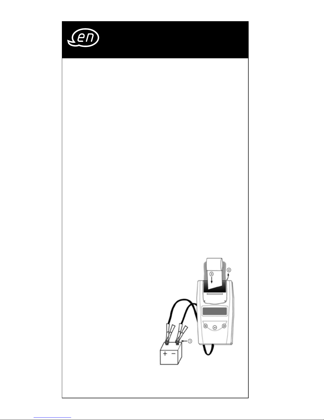
3. Make sure the battery terminals are clean. Wire
brush them if necessary. Clamp the black load
lead to the vehicle negative battery terminal.
Clamp the red load lead to the vehicle positive
battery terminal. Please clamp on the lead part of
the terminal only. Clamping on the iron part of the
terminal will lead to wrong test results.
4. Paper load: Open the
clear cover. Insert paper
to the paper feeding for
auto running the paper
into printer.
5. Spare paper rolls are
available as accesso
ries, please quote the
product code V1923.
Page 23
23
3 Design and Function
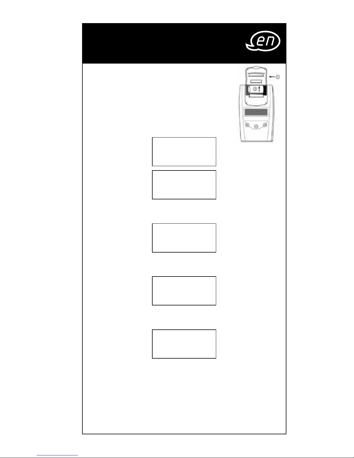
Replace the paper roll
Step 1: Open the clear cover.
Step 2: Pull the paper slowly and straigtly
from the paper roll in the chamber.
5. You will view the following
screens:
SYSTEM ANALYZER
BATTERY TEST |} 8
××.×× V
* Press e / - to select battery test or language.
* Press “Enter” to do battery test.
SYSTEM TEST
|} 8
××.×× V
* Press “Enter” to set language.
* Press e / - back to battery test.
LANGUAGE |} 8
SELECT
* Press “Enter” to set language.
* Press e / - back to battery test.
LANGUAGE
|} 8
ENGLISH
* Press “Enter” to set language.
* Press e / - to select language.
(English, French, German, Spanish, Italian,
Portuguese, Japanese.)
* Press “Enter” to confirm choice and go back to
battery test.
Page 24
24
3 Design and Function
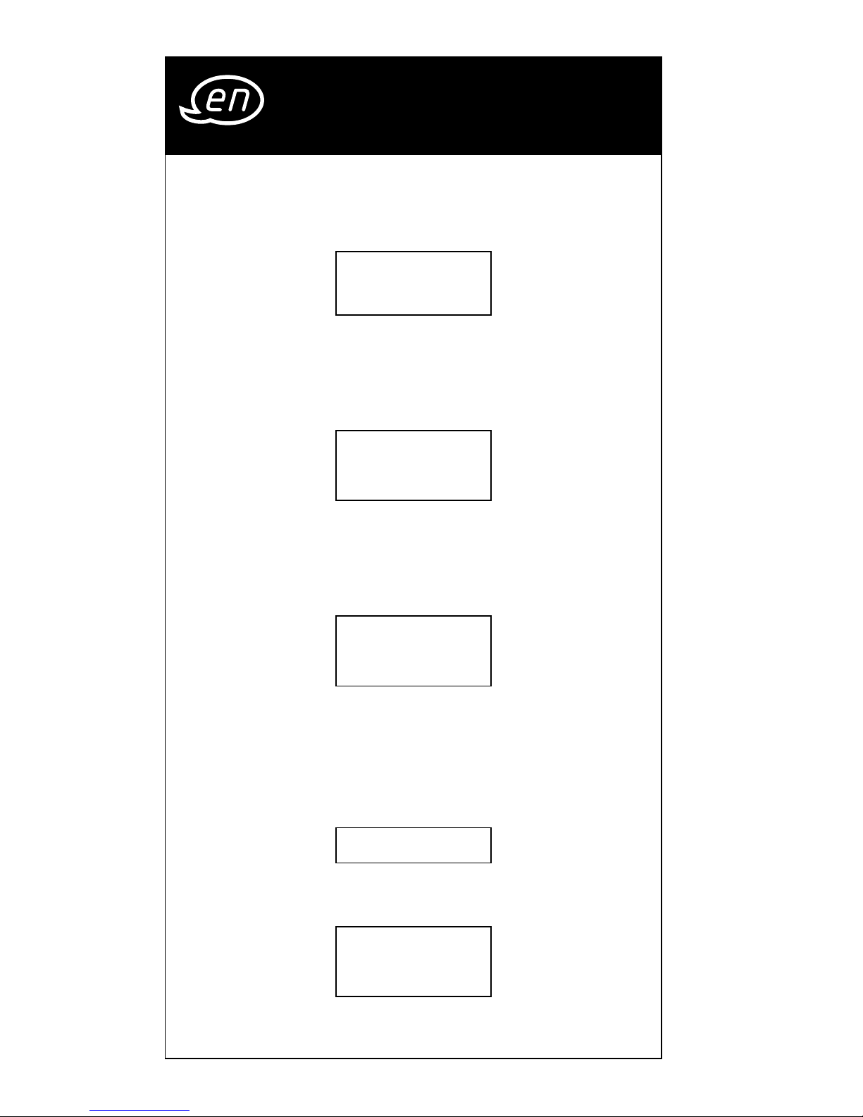
2. Press the
e / -
key to select battery test. Press
«ENTER» button. Example :
3. Press the e / - key to select the battery type:
Batterytyp |} 8
AGM Platte
a REGULAR LIQUID b AGM FLAT PLATE
c AGM SPIRAL d VRLA/GEL
Press «ENTER» to confirm choice.
4. Press the
e / -
key to select the battery rating:
Choose Norm |} 8
SAE
SAE, EN, IEC, DIN or JIS
Press «ENTER» to confirm choice.
5. Press the
e / -
key to input the battery capacity of
CCA:
Capacity CCA |} 8
xxxx SAE
• SAE: 40~2000 • EN: 40~2100
• IEC: 30~1500 • DIN: 25~1300
• JIS: By Battery Type No.
Press «ENTER» to begin the test.
6. Test the battery for few seconds.
TEST runningt
7. Press the
e / -
key to select battery fully charged or
not if tester asks.
Battery is |} 8
charged? Yes
Press «ENTER» to confirm choice.
Page 25
25
3 Design and Function
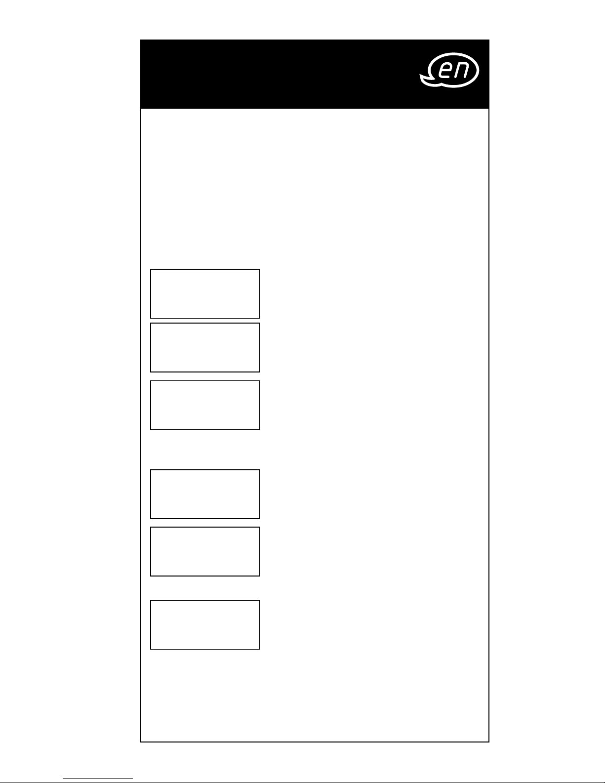
8. When the test is completed, the display shows
the actual volts and the actual CCA or %. The
battery cell tester’s tolerances are +/- 0.05 V
for voltage measurement and +/- 5% CCA for
starting current measurement.
{Press the e / - key
to select: SOH (STATE OF HEALTH)
or SOC (STATE OF
CHARGE)}.
One of six results will be displayed:
GOOD / PASS
xx.xx V xxxx SAE
GOOD / PASS :
The battery is good & capable of
holding a charge.
GOOD / RECHARGE
xx.xx V xxxx SAE
GOOD / RECHARGE :
The battery is good but needs to
be recharged.
RECHARGE / RETEST
xx.xx V xxxx SAE
RECHARGE / RETEST :
Battery is discharged, the battery
condition cannot be determined
until it is fully charged. Recharge
and retest the battery.
BAD / REPLACE
xx.xx V xxxx SAE
BAD / REPLACE :
The battery will not hold a charge.
It should be replaced immediately.
BAD CELL / REPLACE
xx.xx V xxxx SAE
BAD CELL / REPLACE :
The battery has at least one cell
short circuit. It should be replaced
immediately.
LOAD ERROR
LOAD ERROR :
The tested battery is bigger than
2000 CCA or 200 AH. Or the clamps
are not connected properly. Please fully charge
the battery and retest after excluding both previous
reasons. If reading is the same, the battery should be
replaced immediately.
Page 26
26
9. Press the
e / -
key to select result printing:
YES or NO.
PRINT RESULT?|} 8
YES
Press «ENTER» to confirm your choice.
* 24 V System Test Printing:
24 V SYSTEMTEST
PRINT? |} 8
YES
The printer will not function for 24 Volt batteries
system test printing. The 24 V system test result
will be recorded till you hook up to a 12 V battery and the right screen shows up. Please select
“YES” and press enter key to print the result and
then disconnect the clamps. The screen will
appear again after you reconnect the clamps.
Please select “NO” and press the enter key to go
back to the main menu.
10. Press «ENTER» return to step 5 or remove the test
clamps from the battery posts after completion of
testing batteries to end test.
3 Design and Function
Page 27
27
SYSTEM TEST Example :
1.
Press «ENTER» button,
SYSTEM TEST
xx.xx V
you will view the
following screen:
2. Turn off all vehicle accessory
Consumers OFF
START ENGINE
loads such as light, air conditioning, radio, etc. before starting the engine.
3. When the engine is started, one of the three results
will be displayed along with the actual reading
measured.
CRANKING VOLTS NORMAL
CRANKING VOLTS
xx.xx V Normal
The system is showing normal
draw. Press «ENTER» to perform
the charging system test.
CRANKING VOLTS LOW
CRANKING VOLTS
xx.xx V Low
The cranking voltage is below
normal limits, troubleshoot the
starter with manufacturers rec
-
ommended procedure.
CRANKING VOLTS
NO DETECTED
CRANKING VOLTS
No detected
The cranking voltage is not
detected.
4.
If the cranking voltage is
PRESS ENTER to test
charging system
normal, press «ENTER» to begin
charging system test.
5. Press the «ENTER» key, you will
All Consumers
turn off
view the following screen.
3 Design and Function
Page 28
28
6. Press the «ENTER» key, one of the three results will be
displayed along with the actual reading measured.
LOW CHARGING VOLTS WHEN TEST AT IDLE
The alternator is not providing
off-load voltage
xx.xx V Low
sufficient current to the battery.
Check the belts to ensure the
alternator is rotating with engine running. If the belts
are slipping or broken, replace the belts and retest.
Check the connections from the alternator to the
battery. If the connection is loose or heavily cor
roded, clean or replace the cable and retest. If the
belts and connections are in good condition,
replace the alternator.
CHARGING SYSTEM NORMAL WHEN TEST AT IDLE
The system is showing normal
off-load voltage
xx.xx V Normal
output from the alternator. No
problem is detected.
HIGH CHARGING VOLTS WHEN TEST AT IDLE
The voltage output from the
off-load voltage
xx.xx V High
alternator to the battery
exceeds the normal limits of a
functioning regulator. Check to ensure there is no
loose connection and the ground connection is
normal. If there is no connection issue, replace the
regulator. Since most alternators have the regulator
built-in, this will require you to replace the alterna
tor. The normal high limit of a typical automotive
regulator is 14.7 volts +/- 0.05. Check manufacturer
specifications for the correct limit, as it will vary by
vehicle type and manufacturer.
7. Following the charging system at
Consumer on
Press Enter
idle, press «ENTER» for the charg
ing system with accessory loads.
Turn on the blower to high (heat), highbeam head
lights, and rear defogger. Do not use cyclical loads
such as air conditioning or windshield wipers.
3 Design and Function
Page 29
29
8. When testing older model diesel engines, the users
need to run up the engine to 2500 rpm for 15 sec
-
onds. You will view the screen as follows:
Revolution speed
2500/Min 15 SEK
9. Press «ENTER» to look for the amount of ripple from
the charging system to the battery. One of two
testing results will be displayed along with the
actual testing measured.
RIPPLE DETECTED NORMAL
DIODE TEST
xx.xx V Normal
Diodes function well in the
alternator / stator.
or
No
Ripple voltage.
EXCESS RIPPLE DETECTED
DIODE TEST
xx.xx V Hoch
One or more diodes in the
alternator are not functioning
or there is stator damage. Check to ensure the
alternator mounting is sturdy and that the belts
are in good shape and functioning properly. If
the mounting and belts are good, replace the
alternator.
3 Design and Function
Page 30
30
10. Press the «ENTER» key to continue the charging system
with accessory loads. One of the three results will be
displayed along with the actual testing measured.
CHARGING SYSTEM HIGH WHEN TEST WITH
ACCESSORY LOADS
The voltage output from the
Voltage at load
xx.xx V High
alternator to the battery exceeds
the normal limits of a functioning
regulator. Check to ensure there are no loose con
nections and that the ground connection is normal.
If there are no connection issues, replace the regula
tor. Since most alternators have the regulator built-in,
this will require you to replace the alternator.
CHARGING SYSTEM LOW WHEN TEST WITH
ACCESSORY LOADS
The alternator is not providing
Voltage at load
xx.xx V Low
sufficient current for the system’s
electrical loads and the charging
current for the battery. Check the belts to ensure the
alternator is rotating with the engine running. If the
belts are slipping or broken, replace the belts and
retest. Check the connections from the alternator to
the battery. If the connection is loose or heavily cor
roded, clean or replace the cable and retest. If the
belts and connections are in good working condi
tion, replace the alternator.
CHARGING SYSTEM NORMAL WHEN TEST WITH
ACCESSORY LOADS
The system is showing normal
Voltage at load
xx.xx V Normal
output from the alternator. No
problem detected.
11. Press «ENTER» when charging
Voltage at load
xx.xx V Normal
system test is completed finish.
Turn all accessory loads and
engine off. Press «ENTER» to return to step 1 or remove
the test clamps from the battery posts after comple
tion of testing to end test.
3 Design and Function
Page 31

31
What is a GEL battery?
A gel battery is a lead-acid electric storage battery
that:
•
is sealed using special pressure valves and should
never be opened.
•
is completely maintenance-free.*
•
uses thixotropic gelled electrolyte.
•
uses a recombination reaction to prevent the
escape of hydrogen and oxygen gases normally
lost in a flooded lead-acid battery (particularly in
deep cycle applications).
•
is non-spillable, and therefore can be operated in
virtually any position. However, upside-down instal
-
lation is not recommended.
Connections must be retorqued and the batteries
should be cleaned periodically.
What is an AGM battery?
An AGM battery is a lead-acid electric storage battery
that:
•
is sealed using special pressure valves and should
never be opened.
•
is completely maintenance-free.*
•
has all of its electrolyte absorbed in separators consisting of a sponge-like mass of matted glass fibers.
•
uses a recombination reaction to prevent the
escape of hydrogen and oxygen gases normally
lost in a flooded lead-acid battery (particularly in
deep cycle applications).
•
is non-spillable, and therefore can be operated in
virtually any position. However, upside-down instal
-
lation is not recommended.
Connections must be retorqued and the batteries
should be cleaned periodically.
4 Glossary
Page 32

32
What is a VRLA battery?
Valve Regulated Lead Acid Battery – This type of battery is sealed Maintenance Free with a “Bunce” Valve
or Valves in the top of them that opens when a preset
pressure is realized inside the battery and let’s the
excess gas pressure out. Then the valve resets itself.
What is a SLI battery?
These initials stand for Starting, Lighting and Ignition,
which are the three basic functions which a battery
has to perform on all normal vehicles. Batteries given
this description will have been specifically designed
for service on cars and trucks within a voltage con
trolled electrical system. Those SLI batteries which are
intended for heavy haulage vehicles fitted with large
diesel motors may often be called COMMERCIAL bat
teries. They have to be much more powerful and more
robust than batteries intended for cars.
What is STATE OF HEALTH?
It means how much battery capacity is left (%) comparing with the marked original battery capacity.
What is STATE OF CHARGE?
It means how many percent of the battery is actually
charged.
4 Glossary
Page 33

33
What is CCA (COLD CRANKING AMPS)?
The current in amperes which a new fully charged battery can deliver for 30 seconds continuously without
the terminal voltage falling below 1.2 volts per cell,
after it has been cooled to -18° C / 0° F and held at
that temperature. This rating reflects the ability of the
battery to deliver engine starting currents under winter
conditions.
What is AMPERE-HOUR?
The unit of measurement of electrical capacity. A current of one ampere for one hour implies the delivery or
receipt of one ampere-hour of electricity. Current mul
-
tiplied by time in hours equals ampere-hours.
EC-Declaration of Conformity
Product designation: Battery and
charging system tester
Article No.:
ViGOR V 1922
We confirm hereby that the product as described
above has been manufactured in full conformity
with the basic requirements which are defined in
the European EMC Directives (2004/108/EC)
and
2006/95/EG.
Person authorised to compile the technical file: Sandra
Müller, Tel.: +49 (0) 2191 792 319
Date: 15.11.2010
Hermann J. ZERVER
ViGOR GmbH
Am Langen Siepen 13 - 15
D-42857 Remscheid
[email protected]
www.vigor-equipment.com
4 Glossary
Page 34
Page 35
35
1 Pour votre information
IMPORTANT :
1. Pour le test de batteries de 6 et 12 volts et circuits
de charge de 12 et 24 volts.
2. Température de service admissible 0° C (32° F) à
50° C (122° F) (température ambiante)
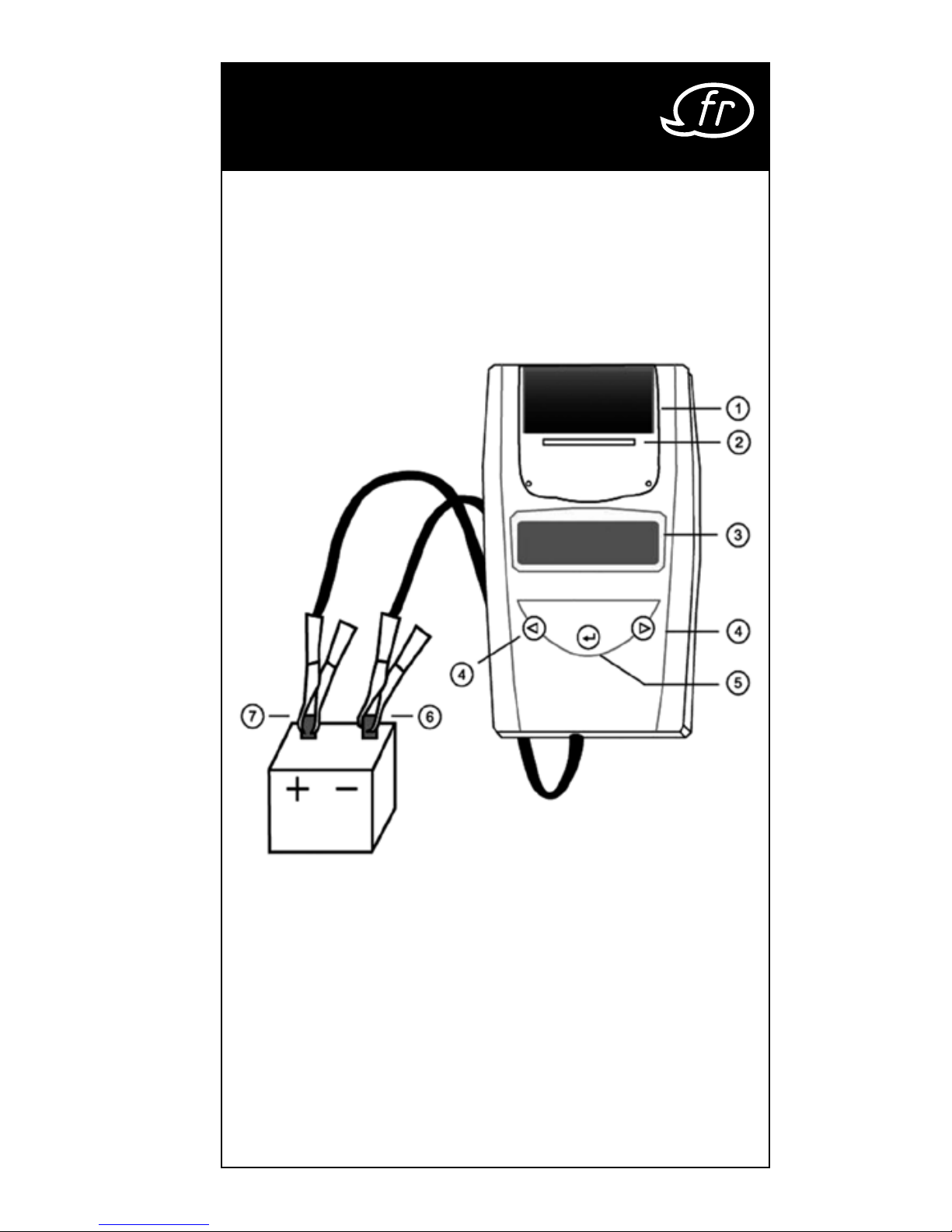
1. Cache transparent
2. Papier imprimante
3. Écran LCD
4. Bouton Haut/Bas
5. ENTER : sélection / validation
6. Pince négative (noire -)
7. Pince positive (rouge +)
Page 36

36
2 Pour votre sécurité
ATTENTION :
1. Il est dangereux de travailler à proximité d’une
batterie. Les batteries en service génèrent des gaz
explosifs. Afin de ne courir aucun risque, il est donc
extrêmement important de lire attentivement les
instructions avant toute utilisation du testeur.
2. Suivez les instructions afin de réduire tout risque
d’explosion de la batterie et lisez les consignes du
fabricant de la batterie et des équipements utilisés
à proximité de cette dernière. Observez impéra
tivement les marquages de sécurité figurant sur
l’appareil.
3. N’exposez pas le testeur à la pluie et à la neige.
MESURES À PRENDRE POUR LA SÉCURITÉ DES
PERSONNES :
1. Lorsque vous travaillez avec une batterie, ayez
toujours une personne à vos côtés qui pourra vous
porter assistance.
2. Préparez une grande quantité d’eau fraîche et
du savon au cas où votre peau, vos vêtements ou
vos yeux entreraient en contact avec l’acide de
batterie.
3. Travaillez en portant des lunettes et des vêtements
de protection.
4. Lavez immédiatement la peau ou les vêtements
ayant été en contact avec l’acide de batterie
avec de l’eau et du savon. En cas de projection
d’acide dans les yeux, rincez-les immédiatement
à l’eau courante froide pendant au moins dix
minutes et consultez un médecin.
5. Ne fumez JAMAIS et évitez les étincelles ou flammes
à proximité d’une batterie ou machine.
6. Veillez à ce qu’aucun outil métallique ne tombe
sur la batterie. Cela peut provoquer des étincelles,
court-circuiter la batterie ou d’autres pièces et
entraîner une explosion.
Page 37

37
2 Pour votre sécurité
7. Lorsque vous travaillez avec la batterie, ne portez
pas de bagues, bracelets, chaînes, montres, etc.
Un éventuel court-circuit peut faire fondre des
objets et entraîner de graves brûlures.
Avant la mise en service :
1. Pendant le test, assurez une bonne ventilation
autour de la batterie.
2. Nettoyez les pôles de la batterie. Le port de
lunettes de protection est obligatoire.
3. Vérifiez si le boîtier est fissuré ou brisé. Une batterie
endommagée ne doit pas être testée.
4. Dans le cas de batteries nécessitant un entretien,
ajoutez de l’eau distillée dans chaque cellule
jusqu’à ce que le niveau du liquide atteigne celui
indiqué par le fabricant. Cette opération permet
de supprimer l’excès de gaz. Évitez tout déborde
-
ment du liquide.
5. Débranchez la prise de terre de la batterie dans le
cas où celle-ci doit être enlevée d’un véhicule afin
d’être testée. Mettez hors tension tous les appareils
se trouvant dans le véhicule pour éviter la forma
-
tion d’étincelles.
Page 38
38
3 Construction et
fonctionnement
Mise en service :
TEST DE BATTERIE
1. Avant de procéder au test de la batterie d’un
véhicule, coupez le contact et arrêtez tous les
consommateurs de courant. Fermez les portes et le
coffre.
2. Quatre piles 1,5 V se trouvent dans le compar
timent à piles du testeur. Si ces piles sont vides,
le message « REMPLACEZ LA PILE INTERNE » ou «
ÉNERGIE FAIBLE » apparaît à l’écran de l’appareil.
Dans ce cas, remplacez les 4 piles 1,5 V avant de
tester la batterie du véhicule. En raison de leur puis
sance de sortie initiale de 1,7 volts, l’utilisation de
piles à combustible n’est pas recommandée.
Veuillez noter que rien n’apparaîtra sur l’affichage tant que le testeur ne sera pas connecté
au support de la batterie.
3. Raccordez le câble noir au pôle négatif de la batterie du véhicule et le câble rouge au pôle positif
de la batterie du véhicule. Vérifiez la bonne tenue
de la pince.
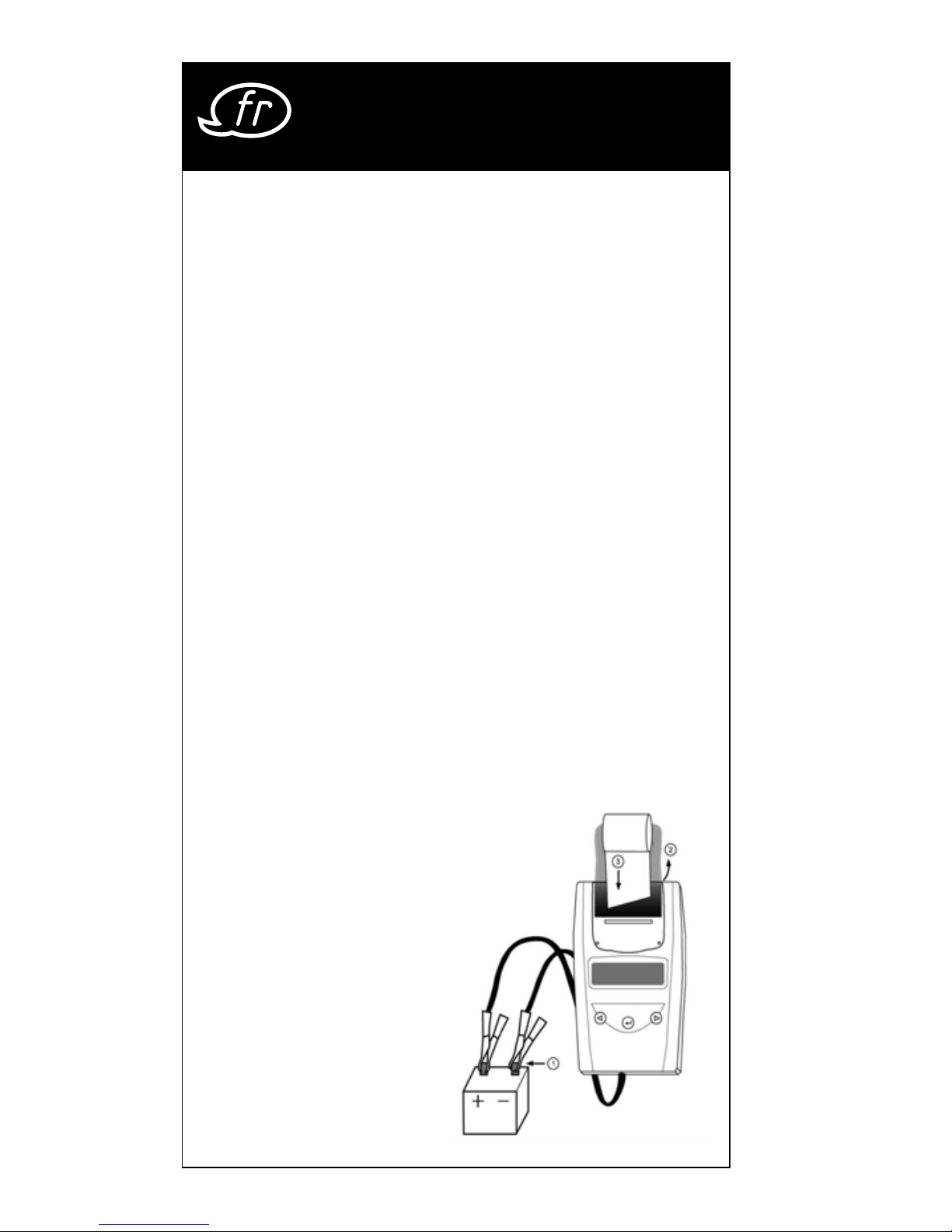
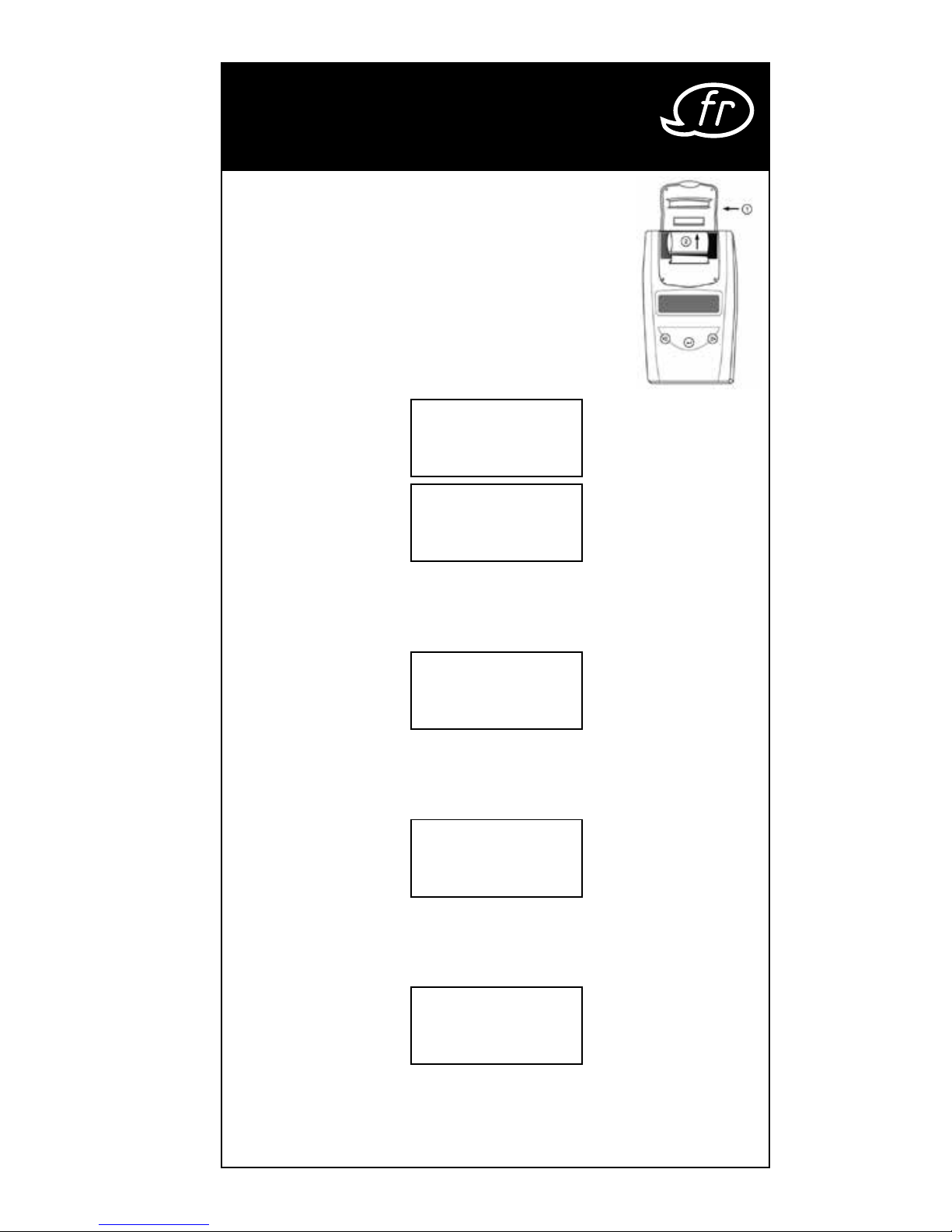
4. Chargement du papier : ouvrez le couvercle.
Insérez le rouleau de
papier de sorte que
le papier soit introduit
automatiquement.
5. Des rouleaux de
rechange faisant par
tie des accessoires sont
disponibles sous la réfé
rence V1923.
Page 39
39
3 Construction et
fonctionnement
Remplacement du rouleau de papier ?
Étape 1 : ouvrir le compartiment transparent.
Étape 2 : introduire le papier lentement et
horizontalement depuis le rouleau jusque
dans le dispositif de guidage.
1. Les messages suivants
apparaissent à l’écran :
SYSTEM TESTER
BATTERIE TEST |} 8
××.×× V
* Appuyez sur
| / }
pour la sélection de la langue ou le
test de système
* Appuyez sur “Enter” pour le test de batterie.
SYSTEM TEST
|} 8
××.×× V
* Appuyez sur
| / }
pour le test de batterie ou la sélec-
tion de la langue
* Appuyez sur “Enter” pour le test de système
LANGUAGE |} 8
SELECT
* Appuyez sur “Enter” pour la sélection de la langue.
* Appuyez sur
| / }
pour le test de batterie ou le test
de système
LANGUAGE
|} 8
FRENCH
* Appuyez sur
| / }
pour la sélection de la langue.
(anglais, français, allemand, espagnol, italien, por
-
tugais, japonais.)
Page 40
40
* Appuyez sur “Enter” pour valider et revenir au test
de batterie.
2. Appuyez sur la touche | / } pour sélectionner le
test de batterie. Appuyez sur «ENTER».
Exemple :
3. Sélectionnez le type de batterie avec la
touche
| / }
:
Type Batterie |} 8
AGM Plaque Plane
a LIQUIDE STANDARD b AGM PLAQUE PLANE
c AGM SPIRALE d VRLA/GEL
Validez la sélection avec «ENTER».
4. À l’aide de la touche
| / }
, sélectionnez la
norme :
Choix de Norme |} 8
SAE
SAE, EN, IEC, DIN ou JIS (Observer impérativement les
données de la batterie)
Validez avec «ENTER».
5. Sélectionnez la capacité de la batterie en
CCA avec la touche
| / }
:
Entrez Capacité CCA |} 8
xxxx SAE
• SAE: 40~2000 • EN: 40~2100
• IEC: 30~1500 • DIN: 25~1300
• JIS: selon le n° de type de la batterie
Pour démarrer le test, appuyez sur «ENTER».
6. Testez la batterie pendant 5 à 7 secondes.
TEST EN COURS
3 Construction et
fonctionnement
Page 41
41
7. Avec la touche
| / }
, sélectionnez l’une des
options, batterie pleinement chargée :
Batterie |} 8
CHARGÉE ? OUI
OUI ou NON. Validez avec «ENTER».
8.
À la fin du test, l’affichage LED indique la tension
actuelle et le CCA ou un %. Les tolérances du
testeur de batterie sont +/- 0,05 V lors de la
mesure de la tension et +/- 5% CCA (ampérage
de démarrage à froid) lors de la mesure du
courant de démarrage à froid.
(Pour choisir
entre SOH (ÉTAT BATT.) ou SOC (ÉTAT DE
CHARGE), appuyez sur la touche
| / }
.
L’un des six résultats apparaît :
BATTERIE OK
xx.xx V xxxx SAE
BATTERIE OK :
La batterie est ok & en mesure de
maintenir la charge.
OK A RECHARGER
xx.xx V xxxx SAE
OK A RECHARGER :
La batterie est ok mais doit être
rechargée.
CHARGER & TESTER
xx.xx V xxxx SAE
CHARGER & TESTER :
La batterie est déchargée, l’état ne
peut pas être déterminé avant une
nouvelle charge. Chargez la batte
-
rie & tester une nouvelle fois.
A REMPLACER
xx.xx V xxxx SAE
A REMPLACER :
La batterie ne maintient pas la
charge. Elle doit être remplacée
immédiatement.
CEL. DÉF. A REMPL
xx.xx V xxxx SAE
CELLULE DÉFECTUEUSE A REMPLACER :
Au moins une cellule de la batterie
est court-circuitée. Un remplace
-
ment immédiat est nécessaire.
3 Construction et
fonctionnement
Page 42
42
ERREUR CHARGE
ERREUR DE CHARGE:
La batterie testée est d’une
capacité supérieure à 2000
CCA ou 200 AH ou les pinces
ne sont pas raccordées correctement. Veuillez
charger la batterie jusqu’à la pleine charge et
testez une nouvelle fois. Si le résultat est le même, la
batterie devrait être remplacée immédiatement.
9. Avec la touche
| / }
, sélectionnez si le résultat
doit être imprimé : OUI
IMPRIMER TEST?|} 8
OUI
ou NON. Validez avec «ENTER».
* Impression du test de système 24 V :
IMPRIMER TEST SYSTÉME
24 V
? |} 8 OUI
l’imprimante ne fonctionne pas pour l’impression
des tests de système des batteries 24 Volts. Le
résultat du test de système 24 V est enregistré
jusqu’à ce que vous raccordiez une batterie
12 V, l’écran de droite apparaîtra par la suite.
Sélectionnez « OUI » et appuyez sur la touche
de validation (ENTER) pour imprimer le résultat.
Enlevez ensuite les pinces. L’écran apparaît à
nouveau une fois que les pinces ont été enlevées. Sélectionnez « NON » et appuyez sur la
touche de validation (ENTER) pour revenir au
menu principal.
3 Construction et
fonctionnement
Page 43
43
10. Un appui sur «ENTER» vous permet de
revenir à l’étape 5 ou vous pouvez enlever
les pinces de test de la batterie pour arrêter
l’appareil.
TEST DE SYSTÈME Exemple :
1. Lorsque vous appuyez sur
TEST DU SYSTÈME
xx.xx V
«ENTER» , l’écran suivant
apparaît :
2.
Arrêtez tous les consommateurs
CONSOMMATEURS ARRÊTÉ
DÉMARRER MOTEUR
de courant du véhicule, tels
que l’éclairage, la climatisa
tion, la radio, etc. avant de
mettre en marche l’appareil.
3. Après le démarrage, l’un des deux résultats appa
-
raît avec la valeur actuellement lue.
TENSION DE DÉMARRAGE
VOLTS DEMARRAGE
xx.xx V NORMAL
NORMALE
Le système affiche un résultat
normal. Appuyez sur «ENTER»,
pour procéder au test de charge.
TENSION DE DÉMARRAGE
VOLTS DEMARRAGE
xx.xx V BAS
FAIBLE
La tension de démarrage est
inférieure aux valeurs normales.
Procédez à la recherche d‘éventuelles anomalies
selon la procédure recommandée par le fabricant
TENSION DE DÉMARRAGE
NON DÉTECTÉE
VOLTS DEMARRAGE
PAS DETECTE
La tension de démarrage n’est
pas détectée.
4. Si la tension de démarrage
APPUYEZ « ENTER »
POUR
TEST DE CHARGE
est normale, appuyez sur
«ENTER», pour démarrer le
test de recharge.
3 Construction et
fonctionnement
Page 44
44
5. Lorsque vous appuyez sur
VERIFIER SI LES
CONSOMM COUPES
«ENTER», l’écran suivant
apparaît
6. Après avoir appuyé sur la touche «ENTER» , l’un
des trois résultats suivants apparaît avec la valeur
actuellement lue.
TENSION DE CHARGE EN L’ABSENCE DE CHARGES
L’alternateur ne fournit pas
ALT. VOLTS REDRES
xx.xx V BAS
suffisamment de courant à la
batterie. Vérifiez la courroie tra
pézoïdale pour être sûr que l’alternateur fonctionne
lorsque le moteur est en marche. Remplacez des
courroies éventuellement détendues ou rompues
et procédez à un nouveau test. Vérifiez la connexion
entre l’alternateur et la batterie. Nettoyez ou rem
placez les câbles corrodés ou détachés et procédez à un nouveau test. Si les courroies et les câbles
sont en bon état, remplacez l’alternateur.
CIRCUIT DE CHARGE NORMAL LORS D’UN TEST EN
L’ABSENCE DE CHARGES
Le système affiche des valeurs
ALT. VOLTS REDRES
xx.xx V Normal
de sortie normales pour l’alternateur. Il n’y a pas de problème.
TENSION DE CHARGE ÉLEVÉE LORS D’UN TEST EN
L’ABSENCE DE CHARGES
La tension de sortie avec laquelle
ALT. VOLTS REDRES
xx.xx V HAUT
l’alternateur alimente la batterie
est supérieure au niveau normal.
Vérifiez s’il y a une connexion détachée ou si la prise
de terre est défectueuse. Si tout est normal, rempla
cez le régulateur. Si le régulateur ne peut pas être
changé tout seul, c’est l’alternateur qui doit être
remplacé. La limite supérieure normale d’un régula
teur de véhicule s’élève à 14,7 volts +/- 0,05. Vérifiez
la limite indiquée par le fabricant, elle varie en
fonction du type de véhicule et du fabricant.
3 Construction et
fonctionnement
Page 45
45
7.
Appuyez ensuite sur
«ENTER»,
ALLUMEZ CONSOM
ET PRESSEZ ENTER
«ENTER», pour tester un circuit
de charge en présence de
charges. Mettez en marche la ventilation (chaleur),
allumez les feux de route et le dégivrage de la
lunette arrière. N’utilisez pas de charges cycliques
comme la climatisation ou les essuie-glaces.
8. Lorsque vous effectuez le test sur des moteurs diesel
plus anciens, faites tourner le moteur à 2500 tr/min
pendant 15 secondes. Le message suivant appa
-
raît :
MOTEUR A
2500 RPM 15 SEC
9. Appuyez sur « ENTER » pour tester l’ondulation
détectée du circuit de charge à la batterie. L’un
des deux résultats suivants apparaît avec le résultat
du test actuel.
TEST DIODES NORMALES
TENSION REDR OK
xx.xx V Normal
Les diodes de l’alternateur
fonctionnent correctement.
OU
TENSION REDR DEF
TEST DIODES ÉLEVÉES
TENSION REDR OK
xx.xx V HAUT
Au moins une diode de l’alter-
nateur ne fonctionne pas ou
est endommagée.
Contrôlez le montage de l’alternateur et le fonc
-
tionnement des courroies trapézoïdales.
10.
Appuyez sur la touche «ENTER» pour continuer le
test du chargeur en présence de charges. L’un des
trois résultats apparaît avec le résultat du test actuel.
3 Construction et
fonctionnement
Page 46
46
ÉTAT DE CHARGE TROP ÉLEVÉ LORS D’UN TEST EN
PRÉSENCE DE CHARGES
L’alternateur charge la batterie
TENSION ALTERNA
xx.xx V HAUT
avec une tension trop élevée.
Contrôlez si toutes les connexions sont en bon état. Si
c’est le cas, le remplacement de l’alternateur est
recommandé.
ÉTAT DE CHARGE TROP FAIBLE LORS D’UN TEST EN
PRÉSENCE DE CHARGES
L’alternateur ne fournit pas
TENSION ALTERNA
xx.xx V BAS
suffisamment de courant pour alimenter les charges du système électrique et la tension de charge de la batterie. Vérifiez les courroies
trapézoïdales pour être sûr que l’alternateur fonc
tionne lorsque le moteur est en marche. Remplacez
des courroies éventuellement détendues ou rom
pues et procédez à un nouveau test. Vérifiez la
connexion entre l’alternateur et la batterie. Nettoyez
ou remplacez les câbles corrodés ou détachés et
procédez à un nouveau test. Si les courroies et les
câbles sont en bon état, remplacez l’alternateur.
ÉTAT DE CHARGE OPTIMAL LORS D’UN TEST EN
PRÉSENCE DE CHARGES
Le système affiche des valeurs
TENSION ALTERNA
xx.xx V Normal
de sortie normales pour
l’alternateur. Il n’y a pas de
problème.
11. Lorsque le test du chargeur est
TEST TERMINE
COUPEZ LE MOTEUR
terminé, appuyez sur «ENTER».
Arrêtez les consommateurs de courant et le
moteur. Un appui sur «ENTER» vous permet de
revenir à l’étape 1 ou vous pouvez enlever les
pinces de test de la batterie à la fin du test.
3 Construction et
fonctionnement
Page 47

47
Qu’est-ce qu’une batterie GEL ?
Une batterie gel est une batterie d’accumulateurs au
plomb qui :
• est scellée avec des soupapes de pression spéciales et
ne doit jamais être ouverte.
• n’a pas besoin d’être entretenue.*
• utilise des électrolytes dans un gel thixotrope.
• utilise une réaction de recombinaison pour éviter
l’échappement d’hydrogène et d’oxygène émis nor
malement dans une batterie d’accumulateurs au
plomb submergée (en particulier pour les applications
en cycle profond).
• est étanche et par conséquent peut être utilisée dans
pratiquement n’importe quelle position. Cependant,
une installation la tête en bas est déconseillée.
Les connexions doivent être resserrées et les batteries
nettoyées périodiquement.
Qu’est-ce qu’une batterie AGM ?
Une batterie AGM est une batterie d’accumulateurs au plomb qui :
• est scellée avec des soupapes de pression spéciales et
ne doit jamais être ouverte.
• n’a pas besoin d’être entretenue.*
• a tous ses électrolytes absorbés dans des séparateurs
composés d’une masse spongieuse de vibres de verre
enchevêtrées.
• utilise une réaction de recombinaison pour éviter
l’échappement d’hydrogène et d’oxygène émis nor
malement dans une batterie d’accumulateurs au
plomb submergée (en particulier pour les applications
en cycle profond).
• est étanche et par conséquent peut être utilisée dans
pratiquement n’importe quelle position. Cependant,
une installation la tête en bas est déconseillée.
Les connexions doivent être resserrées et les batteries
nettoyées périodiquement.
4 Glossaire
Page 48

48
Qu’est-ce qu’une batterie VRLA ?
Une batterie d’accumulateurs au plomb à régulation
par soupapes – Ce type de batterie est scellé, sans
entretien, équipée d’une « soupape Bunce » ou de
plusieurs soupapes sur le dessus qui s’ouvrent quand
une pression prédéfinie est atteinte dans la batterie et
laissent sortir le gaz excédentaire sous pression. La sou
-
pape se referme ensuite automatiquement.
Qu’est-ce qu’une batterie SLI ?
L’abréviation SLI signifie Starting, Lighting and Ignition
(démarrage, éclairage et allumage) qui sont les trois
fonctions de base d’une batterie utilisée sur tous les
véhicules. Les batteries ainsi appelées ont été conçues
spécialement pour une utilisation sur des voitures
et camions dans une gamme de tensions régulée
par un système électrique contrôlé. Ces batteries
SLI destinées à des véhicules gros porteurs avec de
gros moteurs diesel sont souvent appelées batteries
COMMERCIALES. Elles doivent être beaucoup plus
puissantes et robustes que les batteries destinées à des
voitures.
Qu’est-ce que l’ÉTAT DE SANTÉ ?
L’état de santé indique la capacité de batterie restante (en %) comparée à la capacité initiale indiquée
pour la batterie.
Qu’est-ce que l’ÉTAT DE CHARGE ?
L’état de charge indique le pourcentage réel de
charge de la batterie.
4 Glossaire
Page 49

49
Qu’est-ce que le CCA ?
Le courant en ampères qu’une batterie complètement chargée peut fournir de manière continue pendant 30 secondes sans que la tension finale de charge
tombe en dessous de 1,2 volts par cellule après avoir
été refroidie à -18° C / 0° F et maintenue à cette tem
pérature. Cette mesure reflète la capacité de la batterie à fournir des courants de démarrage de moteurs
dans des conditions hivernales.
Qu’est-ce que les AMPÈRES-HEURE ?
Il s’agit de l’unité de capacité électrique. Cette unité
indique la quantité d’électricité transportée en une
heure par un courant de un ampère. Le courant en
ampères multiplié par la durée en heures donne des
ampères-heures.
Déclaration de conformité
Désignation du produit : testeur de batterie et de circuit
de charge
Désignation du modèle : ViGOR V 1922
Nous déclarons que le produit désigné est conforme
aux dispositions définies par la directive UE
Compatibilité Électromagnétique 2004/108/CE et la
directive Basse Tension 2006/95/CE.
Date : 15/11/2010
Hermann J. ZERVER
ViGOR GmbH
Am Langen Siepen 13 - 15
D-42857 Remscheid
[email protected]
www.vigor-equipment.com
4 Glossaire
Page 50
50
Notizen / Notes
Page 51
51
Notizen / Notes
Page 52

ViGOR GmbH • } 10 04 61
D-42804 Remscheid • Germany
[
+49 (0) 21 91 / 97 95 •
\
+49 (0) 21 91 / 97 96 00
]
^
vigor-equipment.com
V 1922 BA III. 04.2014/ ∞ be/234
 Loading...