

Page 1

Vig770S
Motherboard
Manual
C O M P U T E R S N E T W O R K S. S O L U T I O N S
Page 2

2
V1.0
Vig770S Motherboard Manual
Viglen, EMC and the ‘CE’ mark
CE Marking
European standards are being harmonised across borders. If products comply with
the same standards in all European countries, product exporting and importing is
made simple - paving our way to a common market. If you buy a product with a 'CE'
mark on it (shown below), on the box, in the manual, or on the guarantee - it complies
with the currently enforced directive(s).
Introduction to EMC
EMC (Electromagnetic Compatibility) is the term used to describe certain issues with
RF (Radio Frequency) energy. Electrical items should not interfere with each other
through RF emissions. E.g. If you turn on your microwave, your television should not
display interference if both items are CE marked to the EMC directive.
If emitted RF energy is not low, it can interfere with other electrical circuitry - E.g. cars
automatic braking systems have become activated by themselves while in a strong
RF field. As this has, obvious repercussions ALL electrical products likely to cause
RF related problems have to be 'CE' marked from 1st January 1996 onwards.
If a product conforms to the EMC directive, not only should its RF emissions be very
low, but also its immunity to RF energy (and other types) should be high. The
apparatus has to resist many 'real world' phenomena such as static shocks and
mains voltage transients.
Page 3

3
V1.0
Vig770S Motherboard Manual
Viglen’s Environment laboratory
To gain a 'CE' mark, the Viglen computer range has had to undergo many difficult
tests to ensure it is Electromagnetically Compatible. These are carried out in the inhouse 'Environment lab' at Viglen Headquarters. We have made every effort to
guarantee that each computer leaving our factory complies fully with the correct
standards. To ensure the computer system maintains compliance throughout its
functional life, it is essential you follow these guidelines.
Install the system according to Viglen’s instructions
If you open up your Viglen:
Keep internal cabling in place as supplied.
Ensure the lid is tightly secured afterwards
Do not remove drive bay shields unless installing a 'CE' marked peripheral in its
place
The clips or ‘bumps' around the lips of the case increase conductivity - do not
remove or damage.
Do not remove the ferrite ring from the L.E.D cables.
Only use your Viglen computer with 'CE' marked peripherals
This system has undergo testing in accordance with European standards for use in
residential and light industrial areas-this specifies a 10-meter testing radius for
emissions and immunity. If you do experience any adverse effects, which you think is
due to your computer, try moving it at least 10 meters away from the affected item. If
you still experience problems, contact Viglen’s Technical Support department who will
put you straight through to an EMC engineer - s/he will do everything possible to help.
Any modifications made to your Viglen computer system, it might breach EMC
regulations. XMA take no responsibility (about EMC characteristics) of equipment that
has been altered or modified.
This symbol on the product or on its packaging indicates that the product
shall not be collection point for recycling of electrical and electronic
equipment. By ensuring this product is disposed of correctly, you will help
prevent potential negative consequences for the environment and human
health. Which must be treated the same household waste. Instead it
should be handed over to the applicable otherwise be caused by
inappropriate waste handling of this product. The recycling of materials
will help to conserve natural resources. For more information about
recycling of this product, please contact your local city office, your
household waste disposal service or XMA Ltd.
Copyrights and Trademarks
Please note - The material in this manual is subject to change without notice.
Page 4

4
V1.0
Vig770S Motherboard Manual
Trademarks
Microsoft Windows 10 and MS-DOS are registered trademarks of Microsoft
Corporation. IBM PC, XT, AT and PS/2 are trademarks of International Business
Machines Corporation. Core i3/i5/i7
TM
and Pentium® are registered trademarks of Intel
® Corporation. Genie, Vig, Viglen, and Omnino are trademarks of XMA Limited.
Copyright and Patents
This manual and all accompanying software and documentation is a copyrighted versions
and all rights reserved. This product, including software and documentation, may not, in
whole or in part, be copied, photocopied, translated or reduced to any electronic or
machine- readable form, without prior written consent except for copies retained by the
purchaser for backup.
© Copyright 2017 XMA Limited
All Rights Reserved
Vig770S Manual Version 1.0
Liability
No warranty or representation, expressed or implied is complied with respect to either
the documentation, its quality, performance, merchantability or fitness for a particular
purpose. As a result, the documentation is licensed, and you, the licensee, are
assuming the entire risk as to its quality and performance. The vendor reserves the
right to revise this operation manual and all accompanying software and
documentation and to make changes in the content without obligation to notify any
person or organisation of the revision or change.
In no event will the vendor be liable for direct, indirect, special, incidental or
consequential damages arising out of the use or inability to use this product or
documentation, even if advised of the possibility of such damages. In particular, the
vendor shall not have liability for any hardware, software or data stored or used with
the product, including the costs of repairing, replacing or recovering such hardware,
software or data.
Page 5

5
V1.0
Vig770S Motherboard Manual
Table of Contents
Contents
Viglen, EMC and the ‘CE’ mark ............................................................................................... 2
CE Marking ................................................................................................................................ 2
Introduction to EMC ................................................................................................................. 2
Viglen’s Environment laboratory .............................................................................................. 3
Copyrights and Trademarks .................................................................................................... 3
Trademarks ............................................................................................................................... 4
Copyright and Patents............................................................................................................... 4
Liability 4
Chapter 1 Motherboard Overview
................................................................................. 8
1.1 Introduction ...................................................................................................................... 8
Chapter 2 Motherboard....................................................................................................... 9
2.1 Feature Summary ................................................................................................................ 9
2.1.1
Form factor: ........................................................................................................... 9
2.1.2
Processor: .............................................................................................................. 9
2.1.3
Chipset ................................................................................................................... 9
2.1.4
Memory ................................................................................................................. 9
2.1.5
Graphics ................................................................................................................. 9
2.1.6
Audio ..................................................................................................................... 9
2.1.7
LAN ...................................................................................................................... 10
2.1.8
SATA .................................................................................................................... 10
2.1.9
Expansion Capabilities ......................................................................................... 10
2.1.10
Rear I/O Ports ...................................................................................................... 10
2.2 System Board Connectors ................................................................................................. 11
2.2.1
(1) CPU and chassis fan connectors (4-pin CPU_FAN, 4-pin CHA_FAN). ............ 12
2.2.2
(2) ATX power connectors (24-pin EATXPWR, 4-pin ATX12V) ............................ 12
2.2.3
(3) M.2 socket 3 ................................................................................................... 12
2.2.4
(4) Intel® LGA1151 CPU socket ............................................................................ 12
2.2.5
(5) DDR4 DIMM slots ........................................................................................... 12
2.2.6
(6) Intel® B250 Serial ATA .0 GB/s connectors (7-pin SATA6G 1~6). ................... 12
2.2.7
(7) USB 3.0 connector (20-1 pin USB3_12 USB3 910) ......................................... 12
2.2.8
(8) System panel connector (10-1 pin Front Panel) ............................................ 12
2.2.9
(9) Speaker connector (4-1 pin SPEAKER) ............................................................ 12
2.2.10
(10) Chassis intrusion header (4-1 pin CHASSIS) ................................................. 13
2.2.11
(11) Clear RTC RAM (2-pin CLRTC) ...................................................................... 13
Page 6

6
V1.0
Vig770S Motherboard Manual
2.2.12
(12) USB 2.0 connector (10-1 pin USB78) ........................................................... 13
2.2.13
(13) TPM Connector ............................................................................................ 13
2.2.1
(14) LPT connector (26-1 pin LPT) ........................................................................ 13
2.2.1
(15) Serial port connectors (10-1 pin COM) ......................................................... 13
2.2.1
(16) Front panel audio connector (10-1 pin AAFP) .............................................. 13
2.2.1
(17) PCI slot. ......................................................................................................... 14
2.2.1
(18) Mono out header (2-pin MONO_OUT) ........................................................ 14
2.2.1
(19) PCI Express 3.0/2.0 x1 slots .......................................................................... 14
2.2.1
(20) PCI Express 3.0/2.0 x16 slot ......................................................................... 14
2.3 Rear panel connectors ............................................................................................... 15
2.2.1
(1) PS/2 mouse port (green) ................................................................................ 15
2.2.2
(2) Video Graphics Adapter (VGA) port. .............................................................. 15
2.2.3
(3) Display Port .................................................................................................... 15
2.2.4
(4) LAN (RJ-45) port. ............................................................................................ 15
2.2.5
(5) Line in port (light blue). .................................................................................. 16
2.2.6
(6) Line Out port (lime). ....................................................................................... 16
2.2.7
(7) Microphone port (pink). ................................................................................. 16
2.2.8
(8) USB 2.0 ports. ................................................................................................. 16
2.2.9
(9) USB 3.0 ports. ................................................................................................. 16
2.2.10
(10) HDMI port. ................................................................................................... 17
2.2.11
(11) DVI-D port. ................................................................................................... 17
2.2.12
(12) PS/2 keyboard port (purple). ....................................................................... 17
Chapter 3
– System Board Options
.......................................................................................... 18
3.1 Upgrades ........................................................................................................................... 18
3.2 Upgrading the CPU ............................................................................................................ 19
3.3 Connecting the Processor Fan Heat Sink Cable ................................................................ 23
3.4 Installing & Removing Memory Modules ......................................................................... 24
3.5 Removing Memory ............................................................................................................ 25
3.6 PCI Express 3.0/2.0 x16 slots............................................................................................. 25
3.6 Replacing the CMOS Battery ............................................................................................. 26
Chapter 4 - Solving Problems
..................................................................................... 29
4.1 Technical Support ........................................................................................................... 29
4.2 Troubleshooting Procedures ........................................................................................... 30
4.3 Problems & Suggestions .................................................................................................. 31
Chapter 5 -
System BIOS
....................................................................................... 33
5.1 What is the BIOS?
.............................................................................................................. 33
5.2 The Power-On sequence ................................................................................................. 33
5.3 Managing and updating BIOS .......................................................................................... 34
Page 7

7
V1.0
Vig770S Motherboard Manual
5.3.1 Introduction ............................................................................................................. 34
5.3.2 BIOS Update Instructions under DOS ...................................................................... 34
5.4 BIOS Setup Program ........................................................................................................ 36
5.4.1 Entering BIOS Setup ................................................................................................. 36
5.4.2 BIOS menu screen .................................................................................................... 37
5.4.3 BIOS Main Menu selection ...................................................................................... 38
5.4.4 Main menu .............................................................................................................. 39
5.4.5 Air Tweaker menu .................................................................................................... 42
5.5.5 Advanced Menu Screen ........................................................................................... 43
5.5.6 Monitor menu .......................................................................................................... 48
5.5.7 Boot menu ............................................................................................................... 49
BIOS settings for Windows 7 and Windows 10 O/S ......................................................... 50
5.5.8 Configuring Raid 1 in Bios Program ........................................................................ 53
EU Declaration of Conformity ............................................................................................... 56
Motherboard CE certification ............................................................................................... 56
.......................................................................................................................................... 57
Chapter 6
............................................................................................................................ 57
6.1Suggestions
...................................................................................................................... 57
6.2 Questionnaire
................................................................................................................. 57
6.3 Notes ................................................................................................................................. 59
Page 8

8
V1.0
Vig770S Motherboard Manual
Chapter 1 Motherboard Overview
1.1 Introduction
This manual describes the Viglen Vig770S motherboard inside your computer.
The motherboard is the most important part of your computer. It contains the
CPU, memory and graphics circuitry that make the computer work in the correct
manner.
The Vig770S motherboard is an ATX form factor-offering legacy to premium
features. PS/2 mouse/keyboard combo port, integrated Graphics via VGA, DVI,
DisplayPort and HDMI, High Definition Audio via 3 flexible audio jacks and
integrated 10/100/1000 network connection, as well as 2 USB 2.0 and 4 USB
3.0 ports to enrich your multimedia creation experience.
The Vig770S Motherboard supports 7th generation Intel Core i3, i5, and i7
processors, and is backward compatible with 6th generation Intel Core i3, i5, and
i7 processors as well as being Microsoft Windows 7, 8.1 and Windows 10 WHQL
certified.
This manual contains technical information about the Viglen Vig770S
motherboard and other hardware components inside your computer. If you are
new to computers, we recommend that you read the user guide first. If you are
an experienced computer user, this manual should provide all the information
you will need to perform simple upgrades and maintenance.
We hope that this manual is both readable and informative. If you have any
comments for suggestions about how we could improve the format, then please
fill out the form at the back of the manual and send it to us.
Above all, we hope that you enjoy using your Viglen computer.
Page 9

9
V1.0
Vig770S Motherboard Manual
Chapter 2 Motherboard
2.1 Feature Summary
2.1.1
Form factor:
MicroATX Form Factor 9.6 x 9.6 in (244 x 244 mm).
2.1.2
Processor:
Intel® for 7th Generation Core™ i7/Core™ i5/Core™
i3/Pentium®/Celeron® Processors
Intel® for 6th Generation Core™ i7/Core™ i5/Core™
i3/Pentium®/Celeron® Processors
Supports Intel® 14 nm CPU
Supports Intel® Turbo Boost Technology 2.0
The Intel® Turbo Boost Technology 2.0 support depends on the CPU types.
2.1.3
Chipset
Intel® B250 Chipset
2.1.4
Memory
4x DIMM, Max. 64GB, DDR4 2400/2133 MHz Non-ECC, Un-buffered
Memory
2.1.5
Graphics
Integrated Graphics Processor- Intel® HD Graphics support
Multi-VGA output support: HDMI/DVI-D/RGB ports
-
Supports HDMI with max. resolution 4096 x 2160 @ 24 Hz /
2560 x 1600 @ 60 Hz
-
Supports DVI-D with max. resolution 1920 x 1200 @ 60 Hz
-
Supports DisplayPort with max. resolution 4096 x 2304 @ 60
Hz
-
Supports RGB with max. resolution 1920 x 1200 @ 60 Hz
Maximum shared memory of 1024 MB
Supports Intel® InTru™ 3D, Quick Sync Video, Clear Video
HD Technology, Insider™
Supports up to 3 displays simultaneously
2.1.6
Audio
Realtek® ALC887 8-Channel High Definition Audio CODEC *1
Supports: Jack-detection, Front Panel Jack-re-tasking
Page 10

10
V1.0
Vig770S Motherboard Manual
2.1.7
LAN
Intel® 1219LM 1 x Gigabit LAN Controller(s)
2.1.8
SATA
6 x SATA 6Gb/s connector(s)
Internal Connectors
1 x USB 3.0 connector(s) support(s) additional 4 USB 3.0 port(s)
2 x USB 2.0 connector(s) support(s) additional 2 USB 2.0 port(s)
2 x COM port(s) connector(s)
6 x SATA 6Gb/s connector(s)
1 x CPU Fan connector(s) (1 x 4 -pin)
2 x Chassis Fan connector(s) (1 x 4 -pin)
1 x 24-pin EATX Power connector(s)
1 x 8-pin ATX 12V Power connector(s)
1 x Front panel audio connector(s) (AAFP)
1 x Internal speaker connector(s)
1 x System panel(s)
1 x Clear CMOS jumper(s)
2.1.9
Expansion Capabilities
1 x PCI Express 3.0/2.0 x16
2.1.10
Rear I/O Ports
1 x PS/2 keyboard/mouse combo port(s)
1 x DVI-D
1 x Display port
1 x D-Sub
1 x HDMI
1 x LAN (RJ45) port(s)
4 x USB 3.0 (blue)
2 x USB 2.0
3 x Audio jack(s)
Page 11

11
V1.0
Vig770S Motherboard Manual
2.2 System Board Connectors
Figure 1: System Board Components
1
CPU and chassis fan connectors (4-pin
CPU_FAN, 4-pin CHA_FAN1/2)
9
Speaker connector (4-pin SPEAKER)
2
ATX power connectors (24-pin EATXPWR,
8-pin ATX12V)
10
Chassis intrusion header (4-1 pin
CHASSIS)
3
M.2 socket 3
11
Clear RTC RAM (2-pin CLRTC)
4
Intel® LGA1151 CPU socket
12
USB 2.0 connector (10-1 pin USB78
5
DDR4 DIMM slots
13
TPM Connector
6
Intel® B250 Serial ATA 6.0Gb/s connectors
(7-pin SATA6G_1~6)
14
LPT connector (26-1 pin LPT)
7
USB 3.0 connectors (20-1 pin USB3_12,
USB3_910)
15
Serial port connectors (10-1 pin COM)
8
System panel connector (10-1 pin F_PANEL)
16
Front panel audio connector (10-1 pin
AAFP)
17
PCI slot
18
Mono out header (2-pin MONO_OUT)
19
PCI Express 3.0/2.0 x1 slots
20
PCI Express 3.0/2.0 x16 slot
Table 1: System Board Components
Page 12

12
V1.0
Vig770S Motherboard Manual
2.2.1
(1) CPU and chassis fan connectors (4-pin CPU_FAN, 4-pin CHA_FAN).
Connect the fan cables to the fan connectors on the motherboard, ensuring that the
black wire of each cable matches the ground pin of the connector.
NOTE: Do not forget to connect the fan cables to the fan connectors. Insufficient airflow inside
the system may damage the motherboard components. These are not jumpers! Do not place
jumper caps on the fan connectors! The CPU_FAN connector supports a CPU fan of maximum
1A (12 W) fan power.
2.2.2
(2) ATX power connectors (24-pin EATXPWR, 4-pin ATX12V)
Correctly orient the ATX power supply plugs into these connectors and push down
firmly until the connectors completely fit.
NOTE: For a fully configured system, we recommend that you use a power supply unit (PSU) that
complies with ATX 12 V Specification 2.0 (or later version) and provides a minimum power of 350 W.
2.2.3
(3) M.2 socket 3
l These sockets allow you to install an M.2 (NGFF) SSD module.
2.2.4
(4) Intel® LGA1151 CPU socket
Install Intel® LGA1151 CPU into this surface mount LGA1151 socket, which is designed
for sixth Generation Intel® Core™ i7 / i5 / i3, Pentium®, and Celeron® processors.
2.2.5
(5) DDR4 DIMM slots
This motherboard comes with four Double Data Rate 4 (DDR4) Dual Inline Memory
Module (DIMM) sockets. A DDR4 module is notched different from a DDR, DDR2,
or DDR3 module. Install 2 GB, 4 GB, 8 GB, and 16 GB un-buffered non-ECC DDR4
DIMMs into these DIMM sockets.
2.2.6
(6) Intel® B250 Serial ATA .0 GB/s connectors (7-pin SATA6G 1~6).
These connectors connect to Serial ATA 6.0 Gb/s hard disk drives via Serial ATA 6.0
Gb/s signal cables
2.2.7
(7) USB 3.0 connector (20-1 pin USB3_12 USB3 910)
Connect a USB 3.0 module to any of these connectors for additional USB 3.0 front
or rear panel ports. These connectors comply with USB 3.0 specifications and
provide faster data transfer speeds of up to 5Gbps, faster charging time for USBchargeable devices, optimized power efficiency, and backward compatibility with
USB 2.0.
2.2.8
(8) System panel connector (10-1 pin Front Panel)
This connector supports several chassis-mounted functions.
2.2.9
(9) Speaker connector (4-1 pin SPEAKER)
The 4-pin connector is for the chassis-mounted system-warning speaker. The speaker
allows you to hear system warnings.
Page 13

13
V1.0
Vig770S Motherboard Manual
2.2.10
(10) Chassis intrusion header (4-1 pin CHASSIS)
This header is for a chassis-mounted intrusion detection sensor or switch.
Connect one end of the chassis intrusion sensor or switch cable to this
connector. The chassis intrusion sensor or switch sends a high-level signal to this
connector when chassis components, are removed or replaced. The signal is,
generated as a chassis intrusion event.
2.2.11
(11) Clear RTC RAM (2-pin CLRTC)
This header allows you to dis-configure ME and clear the CMOS RTC RAM data of the
system setup information such as date, time, and system passwords.
To erase the RTC RAM:
1. Turn OFF the computer and unplug the power cord.
2. Use a metal object such as a screwdriver to short the two pins.
3. Plug the power cord and turn ON the computer.
4. Hold down the <Del> key during the boot process and enter BIOS setup to reenter data.
NB: If the steps above do not help, remove the on-board battery and short the two pins again to clear
the CMOS RTC RAM data. After clearing the CMOS, reinstall the battery.
2.2.12
(12) USB 2.0 connector (10-1 pin USB78)
Connect the USB module cable to this connector; install the module to a slot opening at
the back of the system chassis. This USB connector complies with USB 2.0
specifications and supports up to 480Mbps connection speed.
2.2.13
(13) TPM Connector
This header allows you to connect a Trusted Platform module.
2.2.1
(14) LPT connector (26-1 pin LPT)
The LPT (Line Printing Terminal) connector supports devices such as a printer.
LPT standardizes as IEEE 1284, which is the parallel port interface on IBM PCcompatible computers.
2.2.1
(15) Serial port connectors (10-1 pin COM)
Connect the serial port module cable to these connectors, and then install the
module to a slot opening at the back of the system chassis.
2.2.1
(16) Front panel audio connector (10-1 pin AAFP)
This connector is for a chassis-mounted front panel audio I/O module that supports HD
Audio standard. Connect one end of the front panel audio I/O module cable to this
connector.
NB: We recommend that you connect a high-definition front panel audio module to this
connector to avail of the motherboard’s high-definition audio capability.
Page 14

14
V1.0
Vig770S Motherboard Manual
2.2.1
(17) PCI slot.
The PCI slot supports cards such as a LAN card, SCSI card, USB card, and other cards
that comply with PCI specifications.
2.2.1
(18) Mono out header (2-pin MONO_OUT)
This internal mono out header allows connection to an internal, low power speaker for
basic system sound capability. The subsystem is capable of driving a speaker load of 2
Ohms at 2 Watts (rms).
2.2.1
(19) PCI Express 3.0/2.0 x1 slots
This motherboard supports two PCI Express x1 network cards, SCSI cards, and other
cards that comply with the PCI Express specifications.
2.2.1
(20) PCI Express 3.0/2.0 x16 slot
This motherboard has a PCI Express 3.0/2.0 x16 slot that supports PCI Express 3.0/2.0
x16 graphic cards complying with the PCI Express specifications.
IRQ assignments for this motherboard
When using PCI cards on shared slots, ensure that the drivers support “Share IRQ” or
that the cards do not need IRQ assignments. Otherwise, conflicts will arise between the
two PCI groups, making the system unstable and the card inoperable.
A B C
D
HD Audio
Shared - - -
XHCI Controller
Shared - -
-
SATA Controller
Shared - -
-
LAN1 l219LM
Shared - -
-
PCIEx16
Shared - -
-
PCIEx1 1
- - Shared
-
PCIEx1 2
- - -
Shared
PCI1
-
Shared - -
M.2_1
Shared - -
-
M.2_2
Shared - -
-
Page 15

15
V1.0
Vig770S Motherboard Manual
2.3 Rear panel connectors
Figure 2: Rear panel connectors
Table 3: Rear panel connectors
2.2.1
(1) PS/2 mouse port (green)
This port is for a PS/2 mouse.
2.2.2
(2) Video Graphics Adapter (VGA) port.
This 15-pin port is for a VGA monitor or other VGA-compatible devices
2.2.3
(3) Display Port
This port is for display compatible devices
2.2.4
(4) LAN (RJ-45) port.
LAN (RJ-45) port. This port allows Gigabit connection to a Local Area Network (LAN)
through a network hub.
LAN port LED indications
1 PS/2 mouse port (green).
7
Microphone port (pink)
2 Video Graphics Adapter (VGA) port.
8
USB 2.0 ports
3 Display port
9
USB 3.0 ports
4 LAN (RJ-45) port.
10
HDMI port.
5
Line In port (light blue).
11
DVI-D port
6 Line Out port (lime).
12
PS/2 keyboard port (purple).
Page 16

16
V1.0
Vig770S Motherboard Manual
Activity/Link LED
Speed LED
Status
Description
Status
Description
Off
No link
OFF
10Mbps connection
Orange
Linked
ORANGE
100Mbps connection
Orange
Data activity
GREEN
1Gbps connection
(Blinking)
Orange (Blinking
then steady)
Ready to wake up
from S5 mode
_ _
2.2.5
(5) Line in port (light blue).
This port connects to the tape, CD, DVD player, or other audio sources.
2.2.6
(6) Line Out port (lime).
This port connects to a headphone or a speaker. In the 4.1, 5.1 and 7.1-channel
configurations, the function of this port becomes Front Speaker Out.
2.2.7
(7) Microphone port (pink).
This port connects to a microphone.
Refer to the audio configuration table for the function of the audio ports in 2.1, 4.1,
5.1, or 7.1-channel configuration.
Audio 2.1, 4.1, 5.1, or 7.1-channel configuration
Port
Headset
2.1channel
4.1-channel
5.1-channel
7.1-channel
Light Blue (Rear panel)
Line In
Rear Speaker
Out
Rear Speaker
Out
Rear Speaker
Out
Lime (Rear panel)
Line Out
Front
Speaker Out
Front Speaker
Out
Front Speaker
Out
Pink (Rear panel)
Mic In
Mic In
Bass/Center
Bass/Center
Lime (Front panel)
- - - Side Speaker
To configure a 7.1-channel audio output:
Use a chassis with HD audio module in the front panel to support a 7.1-channel
audio output.
2.2.8
(8) USB 2.0 ports.
These 4-pin Universal Serial Bus (USB) ports are for USB 2.0, 1.1 devices.
2.2.9
(9) USB 3.0 ports.
These 9-pin Universal Serial Bus (USB) ports are for USB 3.0, 2.0 devices.
Page 17

17
V1.0
Vig770S Motherboard Manual
NB:
USB 3.0 devices used for data storage.
We strongly recommend that you connect USB 3.0 devices to USB 3.0 ports for
faster and better performance from your USB 3.0 devices.
Due to the design of the Intel® 200 series chipset, the xHCI controller controls all
USB devices connected to the USB 2.0 and USB 3.0 ports. Some legacy USB
devices must update their firmware for better compatibility.
2.2.10
(10) HDMI port.
This port is for a High-Definition Multimedia Interface (HDMI) connector, and is HDCP
compliant allowing playback of HD DVD, Blu-Ray, and other protected content.
2.2.11
(11) DVI-D port.
This port is for any DVI-D compatible device.
NB: DVI-D cannot be converted to output from RGB Signal to CRT and is not
compatible with DVI-I.
2.2.12
(12) PS/2 keyboard port (purple).
This port is for a PS/2 keyboard.
Page 18

18
V1.0
Vig770S Motherboard Manual
Chapter 3
– System Board Options
3.1 Upgrades
The Vig770s motherboard is supports Intel® Core i3, i5, i7 and Pentium processors in the
LGA1151 socket. RAM support up to a maximum of 64GB using DDR4 2400/2133MHz Non
ECC Un-buffered DIMMs.
WARNING!
Unplug the system before carrying out the procedures described in this chapter.
Failure to disconnect power before you open the system can result in personal
injury or equipment damage. Hazardous voltage, current, and energy levels are
present in this product. Power switch terminals can have hazardous Voltages
present even when the power switch is off.
The procedures assume familiarity with the general terminology associated with
personal computers and with the safety practices and regulatory compliance
required for using and modifying electronic equipment.
Do not operate the system with the cover removed. Always replace the cover
before turning on the system.
As the colours of the wires in the mains, lead of this computer may not correspond with the
coloured markings identifying the terminals in your plug precede as follows:
The green-and-yellow wire must connect to the terminal. in the plug, which is marked by the
letter E or by the safety Earth symbol Q or coloured green or green- and-yellow.
The wire, which is coloured blue, connects to the terminal, which is marked with the letter N
or coloured black.
The wire, which is coloured brown, connects to the terminal, which is marked with the letter L
or coloured red.
CAUTION!
The Viglen Vig770S motherboard and
associated components are sensitive electronic
devices. A small static shock from your body can
cause expensive damage to your equipment.
Page 19

19
V1.0
Vig770S Motherboard Manual
Make sure you are earthed and free of static charge before you open the computer case.
If you are unsure about upgrading your computer, return it to Viglen so a qualified
engineer can perform the upgrade.
Steps to take to prevent static discharge:
The best way to prevent static discharge is to buy an anti-static strap from your local
electrical shop. While you are wearing the strap and is grounded. Static charge will be
harmlessly when grounded.
Do not remove the component from its anti-static protective packaging until you are
about to install it.
Hold boards by the edges - try not to touch components / interface strips etc.
NOTE: We recommend that you return your computer to the service department for
upgrading. Person who is familiar with handling should only carry out upgrades. As
incorrect installation will invalidate the guarantee.
3.2 Upgrading the CPU
CAUTION!
Before installing or removing a processor, make sure the AC power is disconnected. By
unplugging the power, cord from the computer the standby power LED should not light
up. Failure to do so could damage the processor and the board. To install a processor,
follow these instructions:
Unlatch the processor socket lever by pushing it down and away from the socket.
Figure 4: Unlatch the socket lever
Page 20

20
V1.0
Vig770S Motherboard Manual
Rotate the socket lever to lift the load plate away from the socket (Figure 5, A). Make
sure that the load plate is in the fully open position (Figure 5, B) while being careful not
to damage adjacent components. Do not touch the socket contacts.
Figure 5: Lift the load plate
Remove the processor from its protective cover. Hold the processor only at the edges,
being careful not to touch the bottom of the processor (see Figure 6).
Figure 6: Remove the processor from the protective cover Remove the processor from
the protective cover
Note: Do not discard the processor cover. Always replace the processor cover if you
remove the processor from the socket.
Page 21

21
V1.0
Vig770S Motherboard Manual
Hold the processor with your thumb and index finger oriented as shown in Figure 7 to
align your fingers with the socket finger cuts. Make sure that the processor Pin 1
indicator (gold triangle) is aligned with the pin 1 chamfer on the socket (Figure 7, B) and
that the notches on the processor align with the posts on the socket (Figure 7, C). Lower
the processor straight down without tilting or sliding it in the socket (Figure 7, A).
Figure 7: Install the processor
Page 22

22
V1.0
Vig770S Motherboard Manual
Carefully lower, the socket lever (figure 8), while making sure that the front edge of the
load plate slides under the shoulder screw cap as you lower the lever. Latch the socket
lever under the load plate tab (Figure 8, C, and D). The socket cover (Figure 8, B) will
pop off as shown.
Figure 8: Secure the load plate in place
Pick up the socket cover and remove it from the desktop board.
Page 23

23
V1.0
Vig770S Motherboard Manual
3.3 Connecting the Processor Fan Heat Sink Cable
Connect the processor fan heat sink power cable to the 4-pin processor fan header
(see Figure 9). A fan with a 4-pin connector as shown in Figure 9 advised.
1. Make sure the four hooks are in the proper position before you install the cooler.
Figure 9: Connecting the processor fan
Page 24

24
V1.0
Vig770S Motherboard Manual
3.4 Installing & Removing Memory Modules
Installing Memory
You may install 2GB, 4GB, 8GB and 16GB un-buffered non‑ECC DDR4 DIMMs into the
DIMM sockets.
The motherboard has four DIMM sockets. The motherboard supports the following
memory features:
2x DDR4 DIMMs
Non-ECC (64-bit) memory.
2GB, 4GB, 8GB and 16GB modules.
Memory Speeds 2133/2400MHz
Max. 64GB, DDR4
To install DIMMs, follow these steps:
Observe the precautions in “Before You Begin”.
Turn off the computer and all Peripheral devices.
Remove the computer cover and locate the DIMM sockets.
Holding the DIMM by the edges, remove it from its antistatic package.
Make sure the clips at either end of the socket are, clipped from the socket.
Position the DIMM above the socket. Align the two small notches in the bottom
edge of the DIMM with the keys in the socket. Insert the bottom edge of the DIMM
into the socket.
When the DIMM is seated push down on the top edge of the DIMM until the
retaining clips at the ends of the socket snap into place. Make sure the clips are
firmly in place.
Replace the computer cover.
Figure 10: Memory Installation
Page 25

25
V1.0
Vig770S Motherboard Manual
3.5 Removing Memory
To remove a DIMM, follow these steps:
Observe the precautions in "Before You Begin”.
Turn off all peripheral devices connected to the computer. Turn off the
computer.
Remove the computer cover.
Gently spread the retaining clips at each end of the socket. The DIMM pops
out of the socket. Hold the DIMM by the edges, lift it away from the socket,
and store it in an antistatic package.
Reinstall and reconnect any parts you removed or disconnected to reach the
DIMM sockets.
3.6 PCI Express 3.0/2.0 x16 slots
The PCI Express slot supports the PCI Express interface expansion card. The PCI
Express x16 slot supports up 4.0 GB/s transfer rate.
Figure 12: PCI Express Slot
Note: When adding or removing expansion cards, make sure that you power off the system first.
Important: When adding or removing expansion cards, always turn off the power supply and unplug
the power supplies, power cable from the power outlet. Read the expansion card’s documentation to
check for any necessary additional hardware or software changes.
Page 26

26
V1.0
Vig770S Motherboard Manual
3.6 Replacing the CMOS Battery
Replacing the CMOS RAM Battery
A lithium battery is, installed in the socket on the system board.
The battery has an estimated life expectancy of seven years. When the battery
starts to weaken, it loses voltage; when the voltage drops below a certain level, the
system settings stored in CMOS RAM (for example, the date and time) may be
wrong.
If the battery fails, you will need to replace it with a CR2032 battery or an equivalent.
As long as local ordinance permits, you may dispose of individual batteries as normal
rubbish. Do not expose batteries to excessive heat or any naked flame. Keep all
batteries away from children.
This symbol on the product or on its packaging indicates that the
product should not as household waste; it should be handed over
to the applicable collection point for recycling of electrical a d
electronic equipment. By ensuring this product is disposed of
correctly, you will help prevent potential negative consequences for
the environment and human health, which could otherwise be
caused by inappropriate waste handling of this product. The
recycling of materials will help to conserve natural resources. For more detailed
information about recycling of this product, please contact your local city office, your
household waste disposal service or XMA Ltd.
CAUTION!
Danger of explosion if the battery is incorrectly replaced. Replace only with the same
or equivalent type recommended by Viglen. Discard used batteries according to
manufacturer’s instructions and local regulations for disposal of electronic products.
Page 27

27
V1.0
Vig770S Motherboard Manual
Figure 3.6.1 – Motherboard CMOS Battery
To replace the battery, carry out the following:
1. Turn off all peripheral devices connected to the system.
2. Turn off the system.
3. Remove any components that are blocking access to the battery.
4. Figure 33 shows the battery location. Gently pry the battery free from its socket
using flat screwdriver, taking care to note the "+" and "-" orientation of the battery
(Figure 30, 2).
5. Install the new battery in the socket.
Figure 33: Removing the Battery
Recycling/Takeback Services
XMA recycling and takeback programs come from our commitment to the highest
Page 28

28
V1.0
Vig770S Motherboard Manual
standards for protecting our environment. We believe in providing solutions for you to
be able to responsibly recycle our products, batteries, other components as well as
the packaging materials. Please visit XMA web site for detail on recycling or contact
your account manager.
Page 29

29
V1.0
Vig770S Motherboard Manual
Chapter 4 - Solving Problems
4.1 Technical Support
Technical Support contact details
The first part of this chapter helps you identify and solve problems that might occur when the
system is in use. The second part lists error code messages that might be displayed.
Please remember that if you cannot solve the problem by yourself then you should
contact XMA Technical Support for further assistance.
XMA Technical Support can be reached in the following ways: Telephone: 01727 201 850
Fax: 01727 201 858
Email: technical-support@xma.co.uk
You can also look for support information on our web site: http://www.xma.co.uk/
Device drivers and various useful utilities can be downloaded from our ftp site:
http://download.viglen.co.uk/files/Motherboards/Vig770s
Resetting the System
Before checking your system for hardware problems, it is always a good idea to try
resetting your computer and see if a re-boot can solve the problem. Most software related
problems can be solved simply by re-booting your PC.
To do the following
Press
Soft boot: Clear the system memory and reload
the operating system (also called warm reset).
<Ctrl + Alt + Del>
Cold boot: Clear the system memory, halt
power to all peripherals, restart POST, and
reload the operating system.
Power off/on or reset button (at front of the system)
Page 30

30
V1.0
Vig770S Motherboard Manual
4.2 Troubleshooting Procedures
This section provides instructions to troubleshooting procedure to identify a problem and
locate its source.
CAUTION!
Turn off the system and any peripheral devices before you disconnect any peripheral
cables from the system. Otherwise, you can permanently damage the system or the
peripheral devices.
Plug the system properly into grounded power outlet.
Make sure your keyboard and video display is connected correctly to the system. Turn
on the video display, and turn up its brightness and contrast controls to at least twothirds of the maximum (refer to the documentation supplied with the video display).
If the operating system normally loads from the hard disk drive, make sure there is no
diskette in the diskette drive. If the operating system normally loads from a diskette,
insert the operating system diskette into the drive.
Turn on the system. If the power indicator does not light, but the system seems to be
operating normally, the indicator is probably defective. Monitor the power-on self-test
(POST) execution. Each time you turn on the system, the POST checks the system
board, memory, keyboard, and certain peripheral devices.
NOTE: If the POST does not detect any errors, the system beeps once and boots up.
Errors that do not prevent the boot process (non-fatal errors) display a message that
looks similar to the following:
Error Message Line 1 Error Message Line 2
Press <DEL> for Set-up, <F1> to Boot
You can note the error and press <F1> to resume the boot-up process, or <DEL> to enter
Set-up.
Errors that prevent the boot process from continuing (fatal errors), are communicated by
a series of audible beeps. If this type of error occurs, refer to the error codes and
messages listed at the end of this chapter.
Confirm that the operating system has loaded.
Page 31

31
V1.0
Vig770S Motherboard Manual
4.3 Problems & Suggestions
What happens
What to do
Application software
problems
Try resetting the system.
Make sure all cables are installed correctly.
Verify that the system board jumpers are set properly.
Verify that your system hardware configuration is set correctly. In Setup,
check the values against the system settings you recorded previously. If
an error is evident, (wrong type of drive specified, for example), make the
change in Setup and reboot the system. Record your change.
Make sure the software is properly configured for the system. Refer to the
software documentation for information.
Try a different copy of the software to see if the problem is with the copy
you are using.
If other software runs correctly on the system, contact the vendor of the
software that fails.
If you check all of the above with no success, try clearing CMOS RAM
and reconfiguring the system. Make sure you have your list of system
settings available to re-enter, because clearing CMOS RAM sets the
options to their default values.
Characters on- screen
are distorted or incorrect
Make sure the brightness and contrast controls are properly adjusted on
the monitor.
Make sure the video signal cable and power cables are properly installed.
Make sure your monitor is compatible with the video mode you have
selected.
Characters do not
appear on screen
Make sure the video display is plugged in and turned on.
Check that the brightness and contrast controls are properly adjusted.
Check that the video signal cable is properly installed.
Make sure a video board is installed, enabled, and the jumpers are
positioned correctly.
Reboot the system.
Table 6: Problems and Suggestions
Page 32

32
V1.0
Vig770S Motherboard Manual
Table 8: Problems and Suggestions (Continued)
What happens
What to do
CMOS RAM settings are
wrong
If system settings stored in CMOS RAM change for no apparent reason
(for example, the time of day develops an error), the backup battery may
no longer have enough power to maintain the settings. Replace the
battery (Chapter 2).
Diskette drive light does
not go on when drive is
in use or is tested by
POST
Make sure the power and signal cables for the drive are properly
installed.
Check that the drive is properly configured and enabled in Setup.
Hard drive light does not
go on when drive is in
use or is tested by POST
Make sure the power and signal cables for the drive are properly
installed.
Make sure the front panel connector is securely attached to the system
board headers.
Check that the drive is properly configured and enabled in Setup.
Check the drive manufacturer's manual for proper configuration for
remote hard disk drive activity.
Power-on light does not
go on
If the system is operating normally, check the connector between the
system board and the front panel. If OK, the light may be defective.
Prompt doesn't appear
after system boots
It’s probably switched off.
A serious fault may have occurred consult your dealer service
department / Technical Support.
Setup, can't enter
If you can't enter Setup to make changes, check the switch that disables
entry into Setup (Chapter 2). If the switch is set to allow entry into Setup,
you might need to clear CMOS RAM to the default values and
reconfigure the system in Setup.
System halts before
completing POST
This indicates a fatal system error that requires immediate service
attention. Note the screen display and write down any beep code emitted.
Provide this information to your dealer service department / Technical
Support.
Table 8: Problems and Suggestions Continued
Page 33

33
V1.0
Vig770S Motherboard Manual
Chapter 5 -
System BIOS
5.1 What is the BIOS?
The BIOS (Basic Input Output System) is an important piece of software which is stored in
a ROM (Read Only Memory) chip inside the computer. It consists of the basic instructions
for controlling the disk drives, hard disk, keyboard and serial/parallel ports. The BIOS also
keeps a list of the specifications of the computer in battery-backed RAM (also known as
the CMOS RAM) and provides a special Setup program to change this information.
The BIOS in your Viglen computer is guaranteed to be fully compatible with the IBM
BIOS. American Megatrends Inc, an industrial leader in the field of BIOS software, has
written it.
5.2 The Power-On sequence
When the computer is first switched on, certain instructions in the BIOS are executed to
test various parts of the machine. This is known as the POST (Power-On Self-Test)
routine. When you switch the computer on (or when you press the Reset button or press
<Ctrl> + <Alt>+ <Delete> keys, which has the same effect), you can see on the monitor
that it counts through the memory, testing it. The floppy disk drives are then accessed
and tested, and the various interfaces are checked. If there are any errors, a message is
displayed on the screen.
Page 34

34
V1.0
Vig770S Motherboard Manual
5.3 Managing and updating BIOS
5.3.1 Introduction
Updating BIOS to the latest Viglen approved version is recommended. The number of
options made available for any particular board may vary depending on BIOS Support,
drive support and BIOS update file size. You only use.
ASUS Tek. EzFlash Utility
BIOS Updater (DOS)
Latest BIOS files and Utility are available from Viglen FTP site:
NOTE: Please review the instructions distributed with the upgrade utility before
attempting a BIOS upgrade.
5.3.2 BIOS Update Instructions under DOS
The BIOS Updater allows you to update BIOS in a DOS environment. This utility also
allows you to copy the current BIOS file that you can use as a backup when the BIOS
fails or gets corrupted during the updating process.
Save BIOS update zipped file to a temporary directory.
Extract the necessary files.
Copy the contents of the file to a bootable USB key or CD-ROM media.
Boot the target PC with the device connected or inserted.
Select <F8> during POST to display the Boot Menu and select your bootable
device.
At the DOS prompt Type 'Flash.bat' to launch the BIOS updates process.
Reboot the system once complete.
Enter the BIOS Setup and Ensure to load the BIOS default settings to ensure
system compatibility and stability. Select the Load Optimized Defaults item under
the Exit menu.
IMPORTANT: DO NOT shutdown or reset the system while updating the BIOS!
Doing so may cause system boot failure!
Page 35

35
V1.0
Vig770S Motherboard Manual
5.3.3 BIOS Update Instructions using ASUS Tek. EzFlash Utility
For this method you will require a Flash USB device and required BIOS file.
Insert the USB flash disk that contains the latest BIOS file to the USB port.
During POST press <ALT> + <F2> to enter the ASUS Tek. EzFlash Utility
Navigate through the EzFlash Utility using the arrows keys
Press the Up/Down arrow keys to find the USB flash disk that contains the latest
BIOS, and then press <Enter>.
Press the Up/Down arrow keys to find the BIOS file, and then press <Enter> to
perform the BIOS update process. Reboot the system when the update process
is done.
Note:
This function supports USB flash disks formatted using FAT32/16 on a single partition
only.
Ensure to load the BIOS default settings to ensure system compatibility and stability.
Select the Load Optimized Defaults item under the Exit menu.
IMPORTANT!
During the update process DO NOT shut down the PC or interrupt the process, this
could cause damage to the motherboard.
Page 36

36
V1.0
Vig770S Motherboard Manual
5.4 BIOS Setup Program
This chapter provides basic information on the BIOS Setup program and allows you to
configure the system for optimum use. You may need to run the Setup program when:
An error message appears on the screen during the system booting up, and requests you
to run BIOS SETUP.
You want to change the default settings for customized features.
Note: The items under each BIOS category described in this chapter are under
continuous update for better system performance.
Therefore, the description may be slightly different from the latest BIOS and should be
held for reference only.
5.4.1 Entering BIOS Setup
Power on the computer and the system will start POST (Power On Self-Test) process.
When the message below appears on the screen, press <F2> or <DEL> key to enter
Setup. You can also press <F8> when the message below is on screen to bring up the
Boot Menu.
“Press <Del> or <F2> to enter BIOS setup Menu”
If the message disappears before you respond and you still wish to enter Setup, restart
the system by turning it OFF and On or pressing the RESET button. You may also
restart the system by simultaneously pressing <Ctrl>, <Alt>, and <Delete> keys.
Control Keys
Figure 13: BIOS control keys
After entering the BIOS, the first screen you will see is the Main Menu
Page 37

37
V1.0
Vig770S Motherboard Manual
5.4.2 BIOS menu screen
Figure 14: Bios Menu
The boot device options vary depending on the devices you installed to the system.
The Boot Menu (F8) button is available only when the boot device is installed to the
system.
Page 38

38
V1.0
Vig770S Motherboard Manual
5.4.3 BIOS Main Menu selection
The menu bar on top of the screen has the following main items:
Main
For changing the basic system configuration
Ai Tweaker
For changing the overclocking settings
Advanced
For changing the advanced system settings
Monitor
For displaying the system temperature, power status, and changing
the fan settings
Boot
For changing the system boot configuration
Exit
For selecting the exit options and loading default settings
Menu items
The highlighted item on the menu bar displays the specific items for that menu. For
example, selecting Main shows the Main menu items.
The other items (Ai Tweaker, Advanced, Monitor, Boot and Exit) on the menu bar have
their respective menu items
Page 39

39
V1.0
Vig770S Motherboard Manual
5.4.4 Main menu
The Main menu screen appears when you enter the Advanced Mode of the BIOS Setup
program. The Main menu provides you an overview of the basic system information, and
allows you to set the system date, time, language, and security settings.
Figure 17: Main Menu
5.4.4.1 System Language [English]
Allows you to choose the BIOS language version from the options.
5.4.4.2 System Date [Day xx/xx/xxxx]
Allows you to set the system date.
5.4.4.3 System Time [xx:xx:xx]
Allows you to set the system time.
Page 40

40
V1.0
Vig770S Motherboard Manual
5.4.4.4 Security
The Security menu items allow you to change the system security settings.
If you have forgotten your BIOS password, erase the CMOS Real Time Clock (RTC)
RAM to clear the BIOS password.
The Administrator or User Password items on top of the screen show the default Not
Installed. After you set a password, these items show Installed.
Administrator Password
If you have set an administrator password, we recommend that you enter the
administrator password for accessing the system. Otherwise, you might be able to see
or change only selected fields in the BIOS setup program.
To set an administrator password:
Select the Administrator Password item and press <Enter>.
From the Create New Password box, key in a password, then press <Enter>.
Confirm the password when prompted.
To change an administrator password:
Select the Administrator Password item and press <Enter>.
From the Enter Current Password box, key in the current password, then press
<Enter>.
From the Create New Password box, key in a new password, then press
<Enter> Confirm the password when prompted.
To clear the administrator password, follow the same steps as in changing an
administrator password, but press <Enter> when prompted to create/confirm the
password. After you clear the password, the Administrator Password item on top of
the screen shows Not Installed.
User Password
If you have set a user password, you must enter the user password for accessing the
system. The User Password item on top of the screen shows the default Not Installed.
After you set a password, this item shows Installed.
To set a user password:
Select the User Password item and press <Enter>.
From the Create New Password box, key in a password, then press <Enter>.
Page 41

41
V1.0
Vig770S Motherboard Manual
Confirm the password when prompted.
To change a user password:
Select the User Password item and press <Enter>.
From the Enter Current Password box, key in the current password, then
press <Enter>.
From the Create New Password box, key in a new password, then press
<Enter>.
Confirm the password when prompted.
To clear the user password, follow the same steps as in changing a user password,
but press<Enter> when prompted to create/confirm the password. After you clear the
password, the User Password item on top of the screen shows Not Installed.
Page 42

42
V1.0
Vig770S Motherboard Manual
5.4.5 Air Tweaker menu
The Ai Tweaker menu items allow you to configure overclocking-related items.
Be cautious when changing the settings of the Ai Tweaker menu items. Incorrect field
values can cause the system to malfunction.
The configuration options for this section vary depending on the CPU and DIMM model
installed on the motherboard.
Figure 18: Ai Tweaker Menu
Page 43

43
V1.0
Vig770S Motherboard Manual
5.5.5 Advanced Menu Screen
The Advanced menu items allow you to change the settings for the CPU and other
system devices.
NOTE: Be cautious when changing the settings of the advanced menu items. Incorrect
field values can cause the system to malfunction.
Figure 19: Advanced Sub Menu Screen
5.5.5.1 CPU Configuration
The items in this menu show the CPU-related information that the BIOS automatically
detects.
The items shown in submenu may be different due to the CPU you installed.
Page 44

44
V1.0
Vig770S Motherboard Manual
5.5.5.2 Platform Misc Configuration
The items in this menu allow you to configure the platform-related features.
The items in this menu allow you to configure the platform-related features.
Figure 20: Platform Misc Configuration
5.5.5.3 System Agent (SA) Configuration
Allows you to set the SATA configuration.
Figure 21: System Agent (SA) Configuration
Page 45

45
V1.0
Vig770S Motherboard Manual
5.5.5.4 PCH Configuration
While entering Setup, the BIOS automatically detects the presence of SATA devices.
The SATA Port items show Not Present if no SATA device is installed to the
corresponding SATA port
Figure 22: PCH Configuration
5.5.5.5 USB Configuration
The items in this menu allow you to change the USB-related features.
Figure 23: USB Configuration
Page 46

46
V1.0
Vig770S Motherboard Manual
5.5.5.6 On-board Devices Configuration
Configuration on board device such as audio and serial port configuration.
Figure 24: On-board Devices Configuration
5.5.5.7 APM Configuration
Advanced power management.
Figure 25: APM Configuration
Page 47

47
V1.0
Vig770S Motherboard Manual
5.5.5.8 Network Stack Configuration
This item allows user to disable or enable setting such as the UEFI network stack.
Configuration options:
Figure 26: Network Stack Configuration
5.5.5.9 HDD/SSD SMART Information
Allows you to monitor the status of storage drives.
Page 48

48
V1.0
Vig770S Motherboard Manual
5.5.6 Monitor menu
The Monitor menu displays the system temperature/power status, and allows you to
change the fan settings.
Figure 27: Monitor Menu
Page 49
49
V1.0
Vig770S Motherboard Manual
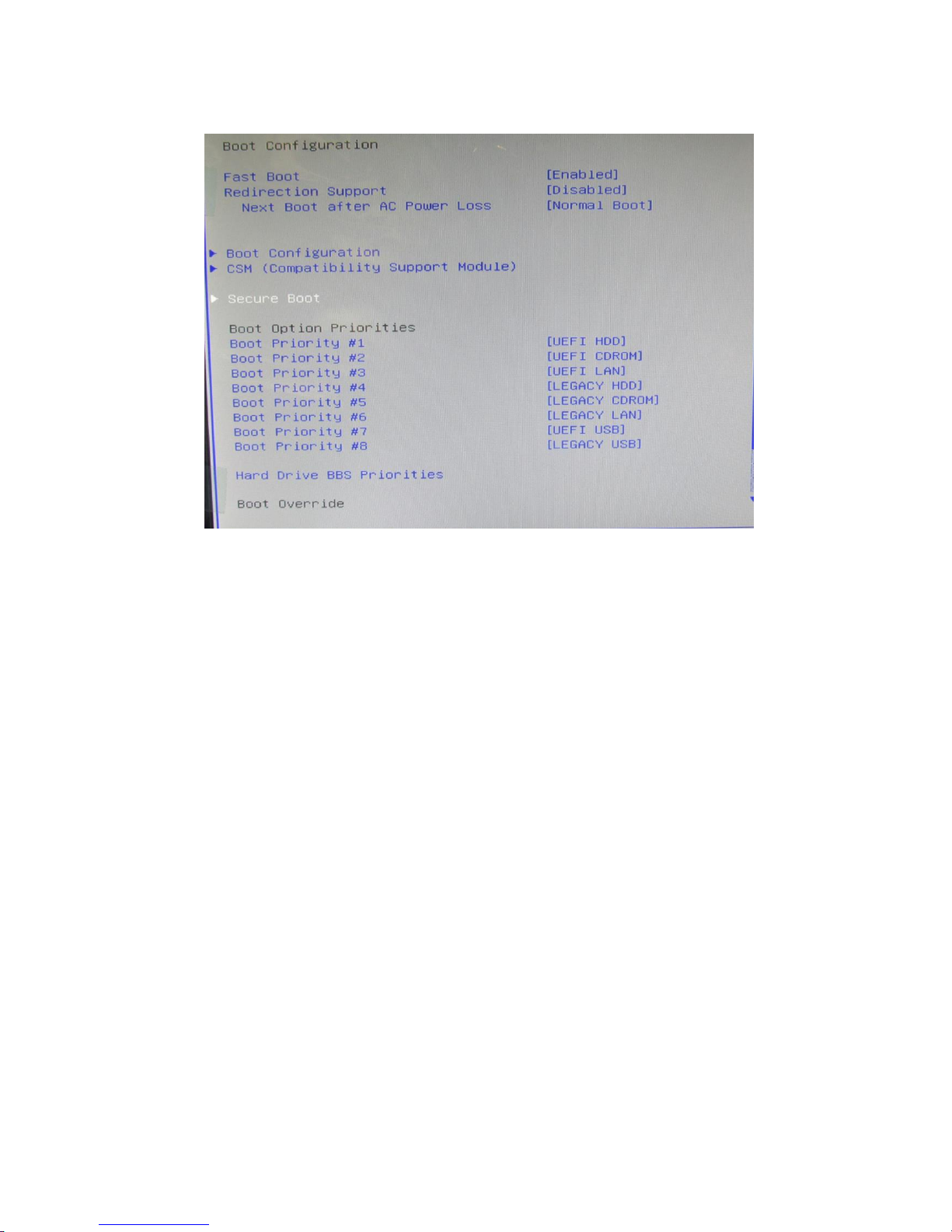
5.5.7 Boot menu
The Boot menu items allow you to change the system boot options.
Figure 28: Boot Menu
Page 50

50
V1.0
Vig770S Motherboard Manual
BIOS settings for Windows 7 and Windows 10 O/S
Windows UEFI mode for Windows 10
Vig770S system configured with Windows 10 will have following default BIOS settings. If
you wish to downgrade to Windows 7 (sixth gen Processors only) then BIOS must be
configured to Non-UEFI mode.
Boot\CSM (Compatibility Support module)
Launch CSM [Enabled]
Boot Device Control [UEFI Only]
Boot from Network Devices [UEFI drivers first]
Boot from Storage Devices [UEFI drivers first]
Boot from PCI-E/PCI Expansion Devices [UEFI drivers first]
Boot\Secure Boot Menu
OS Type [Windows UEFI mode]
Note
Please ensure the changes of the following settings are performed by personnel with some
previous experience/knowledge of altering BIOS settings.
5.5.7.1 Enabling Windows UEFI mode for Windows 10 Operating System
1. From the BIOS main menu bar, select ‘Advanced’
2. Navigate to the Boot sub menu
3. Select CSM (Compatibility Support Module)
Figure 32: Boot Menu
Page 51

51
V1.0
Vig770S Motherboard Manual
4. In the CSM (Compatibility Support Module), change following settings for Windows 10.
Launch CSM [Enabled]
Boot Device Control [UEFI Only]
Boot from Network Devices [UEFI drivers first]
Boot from Storage Devices [UEFI drivers first]
Boot from PCI-E/PCI Expansion [UEFI drivers first]
Figure 33: Compatibility Support Module
Note: When these settings have been changed, press <Esc> or the Back Button to go back
to the Boot Sub Menu to enable Windows UEFI for secure boot.
5. Navigate to Secure Boot from within the Boot sub menu.
6. Change OS Type to Windows UEFI.
Figure 34: Secure Boot Menu
7. Select Key Management.
8. Select Install default Secure Boot keys and select Yes to proceed.
9. Press F10 to Save and exit.
Page 52

52
V1.0
Vig770S Motherboard Manual
BIOS Settings for Windows 7 Operating System (Non-UEFI Mode)
To downgrade to Windows 7 operating system, BIOS settings must be changed to boot into Legacy BIOS
mode (non UEFI Mode).
For Windows 7 operating system BIOS should be configured as per below settings
Boot\CSM (Compatibility Support module)
Launch CSM [Enabled]
Boot Device Control [UEFI and Legacy OPROM first]
Boot from Network Devices [Legacy OPROM]
Boot from Storage Devices [Legacy OPROM]
Boot from PCI-E/PCI Expansion Devices [Legacy OPROM]
Boot\Secure Boot Menu
OS Type [Other OS]
Page 53
53
V1.0
Vig770S Motherboard Manual
5.5.8 Configuring Raid 1 in Bios Program
RAID 1 (Mirroring): A RAID 1 setup protects data from drive failure by simultaneously
writing the same data to two hard drives. Since each drive is an exact duplicate of the
other, you can continue working if one fails. RAID 1 offers no gain in performance and
effectively reduces available capacity by half -- two 2TB drives provide only 2TB of storage.
To perform RAID configuration, you will need the following;
Install two identical drives
Change the SATA Mode Selection to “Intel RST Premium(RAID)” in the BIOS
Create a RAID Volume
Re-image the System.
Change the SATA Mode Selection to “Intel RST Premium (RAID)” in the BIOS
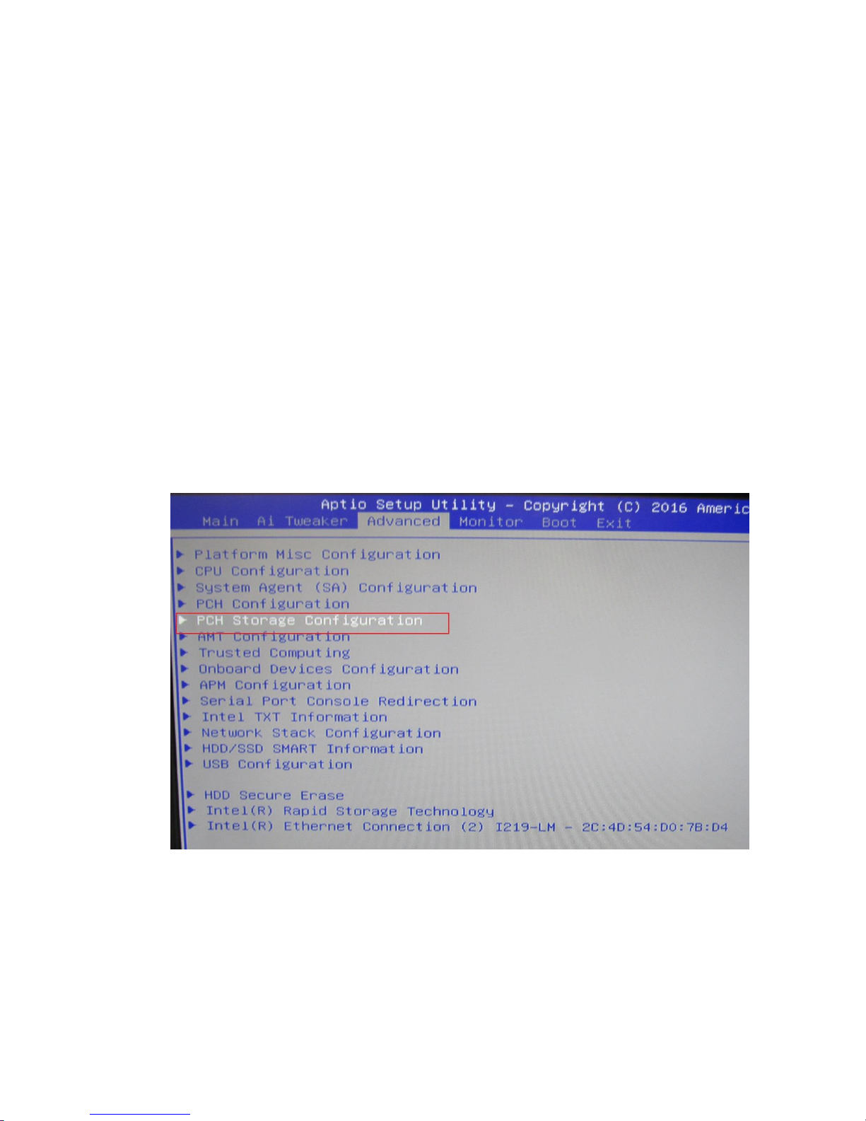
1. Access the bios by pressing the delete or F2 Key.
2. Navigate to the Advance taskbar and select “PCH Storage Configuration”
Figure 5.5.8.1
Page 54

54
V1.0
Vig770S Motherboard Manual
3. Navigate down to “SATA Mode Selection”
4. Select the “Intel RST Premium (RAID)” Option. Now the system has been selected to run in
RAID Configuration.
Figure 5.5.8.2
5. Press the F10 to Save and exit.
System will reboot, Press F2 to access the BIOS Setup.
6. Navigate down to select the “Intel® Rapid Storage Technology” in the advance
taskbar.
Figure 5.5.8.3
Page 55

55
V1.0
Vig770S Motherboard Manual
7. Now select “Create RAID Volume”.
Figure 5.5.8.4
8. Now the system RAID configurations are set-up :
9. Change Name as preferred
10.Select the RAID Level ( i.e. “RAID1(Mirror)”
11.Tick the two hard drives installed in the system.
12.Select “Create Volume” and your done
13.Press F10 to Save and Exit.
Figure 5.5.8.5
Page 56

56
V1.0
Vig770S Motherboard Manual
EU Declaration of Conformity
Motherboard CE certification
Page 57

57
V1.0
Vig770S Motherboard Manual
Chapter 6
6.1Suggestions
6.2 Questionnaire
XMA is interested in continuing to improve the quality and information provided in
their manuals. XMA has listed some questions that you may like to answer and return
to Viglen. This will help Viglen help to keep and improve the standard of their
manuals.
Is the information provided in this and other manuals clear enough?
What could be added to the manual to improve it?
Does the manual go into enough detail?
Would you like an on-line version of this manual?
Page 58

58
V1.0
Vig770S Motherboard Manual
How do you rate the Viglen Technical support and Service Departments?
Are there any technological improvements that could be made to the system?
Other points you would like to mention?
Please return this slip to: Product Development Dept.
XMA Ltd.
7 Handley Page Way Colney Street
St Albans Hertfordshire AL2 2DQ
Page 59

59
V1.0
Vig770S Motherboard Manual
6.3 Notes
 Loading...