

Page 1

C O M P U T E R S N E T W O R K S S O L U T I O N S
..
Vig820S
Motherboard
Manual
Page 2

V1.0 Vig820S Motherboard Manual
1
Viglen, EMC and the ‘CE’ mark
CE Marking
European standards are being harmonised across borders. If products comply with the same standards in all
European countries, product exporting and importing is made simple - paving our way to a common market. If you buy
a product with a 'CE' mark on it (shown below), on the box, in the manual, or on the guarantee - it complies with the
currently enforced directive(s).
Introduction to EMC
EMC (Electromagnetic Compatibility) is the term used to describe certain issues with RF (Radio Frequency) energy.
Electrical items should be designed so they do not interfere with each other through RF emissions. E.g. If you turn on
your microwave, your television shouldn't display interference if both items are CE marked to the EMC directive.
If emitted RF energy is not kept low, it can interfere with other electrical circuitry - E.g. Cars Automatic Braking
Systems have been known to activate by themselves while in a strong RF field. As this has obvious repercussions
ALL electrical products likely to cause RF related problems have to be 'CE' marked from 1st January 1996 onwards.
If a product conforms to the EMC directive, not only should its RF emissions be very low, but its immunity to RF energy
(and other types) should be high. The apparatus has to resist many 'real world' phenomena such as static shocks and
mains voltage transients.
Viglen’s Environment laboratory
To gain a 'CE' mark, the Viglen computer range has had to undergo many difficult tests to ensure it is
Electromagnetically Compatible. These are carried out in the in-house 'Environment lab' at Viglen Headquarters. We
have made every effort to guarantee that each computer leaving our factory complies fully with the correct standards.
To ensure the computer system maintains compliance throughout its functional life, it is essential you follow these
guidelines.
Install the system according to Viglen’s instructions
If you open up your Viglen:
Keep internal cabling in place as supplied.
Ensure the lid is tightly secured afterwards
Do not remove drive bay shields unless installing a 'CE' marked peripheral in its place
The clips or ‘bumps' around the lips of the case increase conductivity - do not remove or damage.
Do not remove the ferrite ring from the L.E.D cables.
Only use your Viglen computer with 'CE' marked peripherals
This system has been tested in accordance with European standards for use in residential and light industrial areasthis specifies a 10 meter testing radius for emissions and immunity. If you do experience any adverse affects which
you think might be related to your computer, try moving it at least 10 meters away from the affected item. If you still
experience problems, contact Viglen’s Technical Support department who will put you straight through to an EMC
engineer - s/he will do everything possible to help. If modifications are made to your Viglen computer system, it might
breach EMC regulations. Viglen take no responsibility (with regards to EMC characteristics) of equipment which has
been tampered with or modified.
This symbol on the product or on its packaging indicates that the product shall not be treated as household
waste. Instead it shall be handed over to the applicable collection point for recycling of electrical and
electronic equipment. By ensuring this product is disposed of correctly, you will help prevent potential
negative consequences for the environment and human health, which could otherwise be caused by
inappropriate waste handling of this product. The recycling of materials will help to conserve natural
resources. For more detailed information about recycling of this product, please contact your local city
office, your household waste disposal service or Viglen Ltd.
Page 3

V1.0 Vig820S Motherboard Manual
2
Copyrights and Trademarks
Please note
The material in this manual is subject to change without notice.
Trademarks
Microsoft, Windows XP Pro, Windows Vista, Windows 7, Windows 8 and MS-DOS are
registered trademarks of Microsoft Corporation. IBM PC, XT, AT and PS/2 are
trademarks of International Business Machines Corporation. Core i3/i5/i7TM and
Pentium® are registered trademarks of Intel® Corporation. All other trademarks are
acknowledged. Genie, Vig, Viglen, and Omnino are trademarks of Viglen Limited.
Copyright and Patents
This manual and all accompanying software and documentation are copyrighted and all
rights reserved. This product, including software and documentation, may not, in whole
or in part, be copied, photocopied, translated or reduced to any electronic or machinereadable form, without prior written consent except for copies retained by the purchaser
for backup.
© Copyright 2013 Viglen Limited
All Rights Reserved
Vig820S Manual Version 1.0
Printed in the United Kingdom
Liability
No warranty or representation, either expressed or implied, is made with respect to this
documentation, its quality, performance, merchantability or fitness for a particular
purpose. As a result the documentation is licensed as is, and you, the licensee, are
assuming the entire risk as to its quality and performance. The vendor reserves the right
to revise this operation manual and all accompanying software and documentation and
to make changes in the content without obligation to notify any person or organisation of
the revision or change.
In no event will the vendor be liable for direct, indirect, special, incidental or
consequential damages arising out of the use or inability to use this product or
documentation, even if advised of the possibility of such damages. In particular, the
vendor shall not have liability for any hardware, software or data stored or used with the
product, including the costs of repairing, replacing or recovering such hardware, software
or data.
Page 4

V1.0 Vig820S Motherboard Manual
3
Contents
Chapter 1: Motherboard Overview 4
Introduction 4
Feature Summary 5
System Board Components 13
Back Panel Connectors 14
Chapter 2: System Board Options 15
Before You Begin 16
System Board Jumper Settings 17
Motherboard Connectors 18
Upgrading the CPU 24
Installing & Removing Memory Modules 28
Replacing the Clock/CMOS RAM Battery 30
Chapter 3: Solving Problems 31
Resetting the System 31
Troubleshooting Procedures 32
Problems & Suggestions 33
Chapter 4: System BIOS 35
What is the BIOS? 35
The Power-On Sequence 35
Managing and Updating BIOS 36
BIOS Setup 39
Windows 8/8.1 BIOS Setting 74
Chapter 5: Suggestions 81
Page 5

V1.0 Vig820S Motherboard Manual
4
Chapter 1: Motherboard Overview
Introduction
This manual describes the Viglen Vig820S motherboard inside your computer. The
motherboard is the most important part of your computer. It contains the CPU, memory
and graphics circuitry that make the computer work in the correct manner.
The Vig820S motherboard with Thin Mini-ITX form factor offers premium features.
Integrated Graphics via HDMI and DisplayPort, High Definition Audio via 2 flexible audio
jacks and integrated 10/100/1000 network connection, as well as 2 USB 3.0 ports and 2
USB 2.0 ports to enrich your multimedia experience.
The Vig820S supports 4th generation Intel Core i3, i5, i7, Pentium and Celeron
processors as well as being Microsoft Windows 8 Premium WHQL certified.
This manual contains technical information about the Viglen Vig820S motherboard and
other hardware components inside your computer. If you are new to computers we
recommend that you read the user guide first. If you are an experienced computer user
this manual should provide all the information you will need to perform simple upgrades
and maintenance.
We hope that this manual is both readable and informative. If you have any comments
for suggestions about how we could improve the format then please fill out the form at
the back of the manual and send it to us.
Above all we hope that you enjoy using your Viglen computer.
Page 6

V1.0 Vig820S Motherboard Manual
5
Feature Summary
Form factor:
Thin Mini-ITX Form Factor: 170mm x 170mm
Processor:
Intel® Core™ i7, Intel® Core™ i5, Intel® Core™ i3, Intel® Pentium®, Intel®
Celeron® processors in an LGA1150 socket
Integrated graphics processing (processors with Intel® Graphics Technology)
External graphics interface controller
Integrated memory controller
Chipset
Intel® Q87 Express Chipset
Memory
Two 204-pin Double Data Rate 3 (DDR3) Small Outline Dual Inline
Memory Module (SO-DIMM) sockets
Support for DDR3 1333/1600 MHz SO-DIMMs
Maximum 16GB Memory Size
Graphics
Integrated graphics support for processors with Intel® graphics technology
1x HDMI® port supporting a maximum resolution of 4096x2160
1x DisplayPort® supporting a maximum resolution of 2560x1600
1x LVDS connector
Audio
Integrated HD audio codec by Realtek® ALC887
Support JACK detection, multi-streaming and anti-pop functions
With ALC105 amplifier to support speakers
Front panel header
LAN
1x Realtek GbE LAN chip (10/100/1000 Mbits/s)
1x Intel GbE LAN chip (10/100/1000 Mbits/s)
Rear I/O Ports
1 x 12V-19V Power Port
1x HDMI
2x Gigabit LAN
1x Microphone
1x Headphone/Speaker
4x USB 3.0 Ports
Page 7

V1.0 Vig820S Motherboard Manual
6
Internal Connectors
1x 2-pin Power Connector
1x 4-pin CPU Fan Header
1x 4-pin System Fan Header
4x SATA 6Gb/s Connectors
1x mSATA Connector
1x SATA Power Connector
5x USB 2.0/1.1 Headers
1x USB 3.0 Header
1x Serial Port Header
1x Parallel Port Header
1x Front Panel Header
1x Front Panel Audio Header
1x Digital Microphone Header
1x AIO Speaker Header
1x LVDS Connector
1x LVDS Drive Voltage Header
1x Flat Panel Display Power Header (both panel and backlight inverter)
1x Flat panel Display Power Connector
1x Backlight Switch Header
1x Flat Panel Display Switch Header
1x WIFI activity Indicator LED Header
1x Clear CMOS Jumper
Expansion Capabilities
1x mini PCIE full card slot
1x mini PCIE half card slot
BIOS
AMI EFI BIOS
Page 8

V1.0 Vig820S Motherboard Manual
7
Processor
The motherboard is designed to support the Intel Core i7/i5/i3, Pentium and Celeron
processors in an LGA1150 socket.
Other processors may be supported in the future. This board is designed to support
processors with a maximum TDP of 65 W.
Chipset
Intel Q87 Express Chipset with Intel Flexible Display Interconnect (Intel FDI) and
Direct Media Interface (DMI) interconnect provides interfaces to the processor, display,
USB, SATA, LPC, LAN, and PCI Express interfaces. The Intel Q87 Express
Chipset is a centralized controller for the board’s I/O paths.
Memory
The board has two SO-DIMM sockets and supports the following memory features:
Two 204-pin DDR3 SDRAM Small Outline Dual Inline Memory Module (SODIMM)
sockets
Support for DDR3 1600 MHz and DDR3 1333 MHz SODIMMs
Support for 1GB, 2GB, 4GB & 8GB memory technology
Support for up to 16 GB of system memory with two 8GB SO-DIMMs
Support for non-ECC memory
Support for 1.5 V (standard voltage) and 1.35 V (low voltage) JEDEC memory
Support for XMP memory
NOTE
To be fully compliant with all applicable DDR SDRAM memory specifications, the board
should be populated with SO-DIMMs that support the Serial Presence Detect (SPD) data
structure. This allows the BIOS to read the SPD data and program the chipset to
accurately configure memory settings for optimum performance. If non-SPD memory is
installed, the BIOS will attempt to correctly configure the memory settings, but
performance and reliability may be impacted or the SO-DIMMs may not function under
the determined frequency.
Page 9

V1.0 Vig820S Motherboard Manual
8
Memory Configurations
The 4th generation Intel Core processor family supports the following types of memory
organization:
• Dual channel (Interleaved) mode. This mode offers the highest throughput for real world
applications. Dual channel mode is enabled when the installed memory capacities of
both SO-DIMM channels are equal. Technology and device width can vary from one
channel to the other but the installed memory capacity for each channel must be equal. If
different speeds SO-DIMMs are used between channels, the slowest memory timing will
be used.
• Single channel (Asymmetric) mode. This mode is equivalent to single channel
bandwidth operation for real world applications. This mode is used when only a single
SO-DIMM is installed or the memory capacities are unequal. Technology and device
width can vary from one channel to the other. If different speed SO-DIMMs is used
between channels, the slowest memory timing will be used.
• Flex mode. This mode provides the most flexible performance characteristics. The
bottommost DRAM memory (the memory that is lowest within the system memory map)
is mapped to dual channel operation; the topmost DRAM memory (the memory that is
nearest to the 8 GB address space limit), if any, is mapped to single channel operation.
Flex mode results in multiple zones of dual and single channel operation across the
whole of DRAM memory. To use flex mode, it is necessary to populate both channels.
Graphics Subsystem
The board supports system graphics through Intel Graphics Technology.
Integrated Graphics
The board supports integrated graphics through the Intel® Flexible Display Interface
(Intel® FDI) for processors with Intel Graphics Technology.
NOTE: If using a processor with integrated graphics, the board will support only two of
the three integrated graphics interfaces simultaneously: HDMI, DisplayPort, LVDS.
High-Definition Multimedia Interface (HDMI)
The HDMI port supports standard, enhanced, or high-definition video, plus multichannel
digital audio on a single cable. It is compatible with all ATSC and DVB HDTV standards
and supports 8 full range channels at 24-bit/96kHz audio of lossless audio formats such
as Dolby TrueHD or DTS HD Master Audio. The maximum supported resolution is
4096x2160.
The HDMI port is compliant with the HDMI 1.3 specification.
Page 10

V1.0 Vig820S Motherboard Manual
9
Audio Subsystem
The motherboard supports Intel High Definition Audio through a Realtek ACL887 audio
codec. The following software features are supported
Compatible with Windows Vista Premium (complies with Microsoft WLP 3.08
specifications)
WaveRT-based audio function driver and logo ready for Windows Vista
Direct Sound 3D
™
compatible
A3D™ compatible
I3DL2 compatible
HRTF 3D Positional Audio
Friendly user interface for 2-foot or 10-foot remote control applications
Emulation of 26 sound environments to enhance gaming experience
10 Software Equalizer Bands
Voice Cancellation and Key Shifting in Karaoke mode
Windows Vista style configuration panel to improve user experience
Microphone Acoustic Echo Cancellation (AEC), Noise Suppression (NS), and
Beam Forming (BF) technology for voice application
Features Dolby
®
Digital Live and DTS® CONNECT™ software (Optional)
Features Dolby
®
Home Theater software (Optional)
These audio connectors are used for audio devices. It is easy to differentiate between
audio effects according to the colour of audio jacks.
Figure 1: Audio Connectors
Line-Out (Green) - Line Out, is a connector for speakers or headphones.
Mic (Pink) - Mic, is a connector for microphones.
Page 11
V1.0 Vig820S Motherboard Manual
10
LAN Subsystem
The ethernet controllers support the following features:
• 10/100/1000 BASE-T IEEE 802.3 compliant
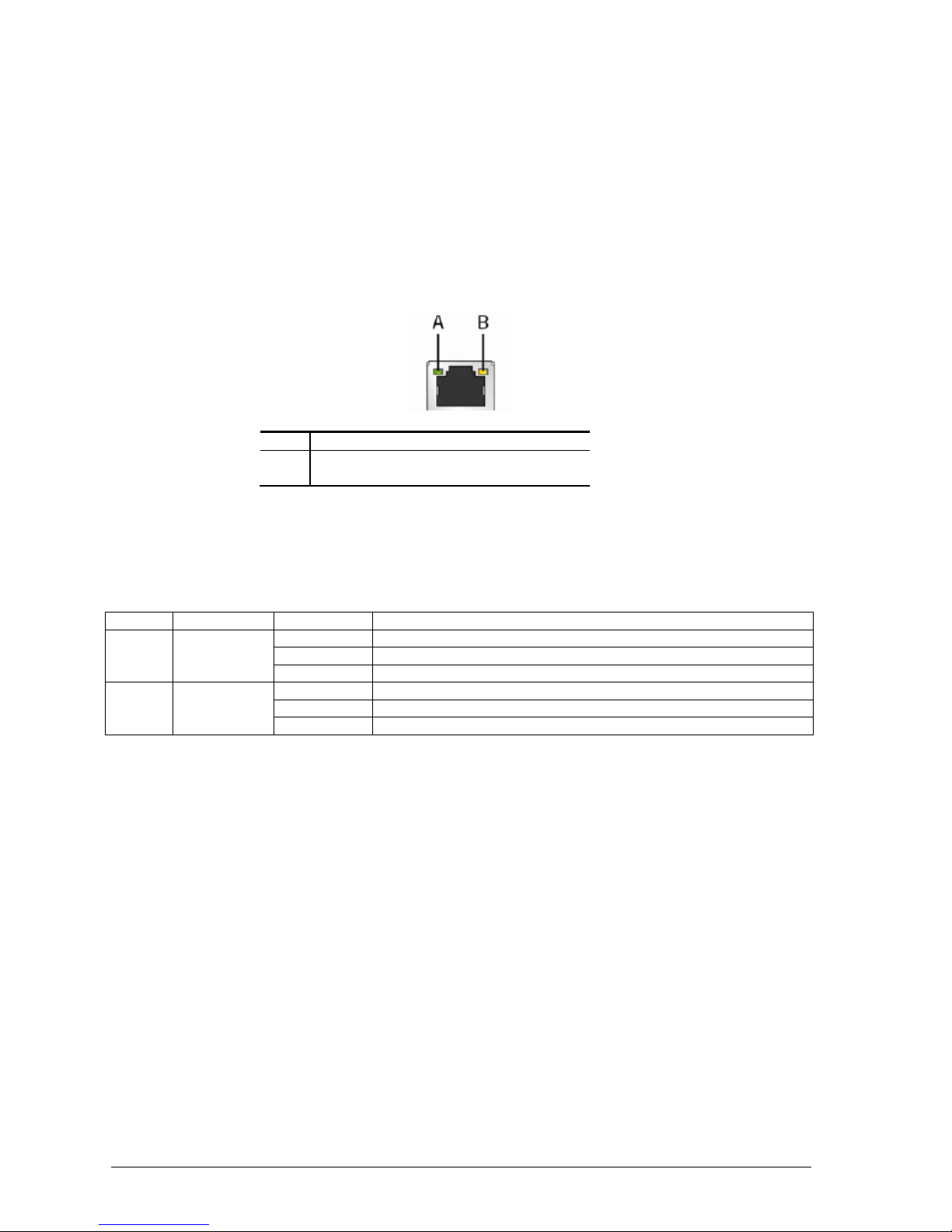
RJ-45 LAN Connector LEDs
The two LEDs are built into the RJ-45 LAN connector located on the back panel. These
LEDs indicate the status of the LAN as shown in Table 1.
Item
Description
A
Link/Activity LED (Green)
B
Link Speed LED (Orange/Yellow)
Figure 2: LAN Connector LED Locations
Table 1: LAN LED Status
LED
LED Colour
LED State
Description
Link
Green
Off
LAN activity is occurring.
On
LAN link is established.
Blinking
LAN activity is occurring.
Data
rate
Green/yellow
10 Mb/s data rate is selected.
100 Mb/s data rate is selected.
1000 Mb/s data rate is selected.
Page 12

V1.0 Vig820S Motherboard Manual
11
Universal Serial Bus (USB)
The motherboard supports up to eleven USB ports. The port arrangement is a follows:
Four USB 3.0 ports are implemented with stacked back panel connectors
Five USB 2.0 front panel ports are implemented through two dual-port and one single
port internal headers
Two USB 3.0 front panel ports are implemented through one dual-port internal header
NOTE: Computer systems that have an unshielded cable attached to a USB port may
not meet FCC Class B requirements, even if no device or a low-speed (sub-channel)
USB device is attached to the cable. Use shielded cable that meets the requirements for
high-speed (fully rated) devices.
SATA Support
The board provides four 6GB/s SATA connectors, which support one device per
connector.
NOTE: By default the SATA mode is set to AHCI in the BIOS to improve system
performance. During Microsoft Windows XP installation, you must press F6 to install the
AHCI drivers. Both Microsoft Windows Vista and Microsoft Windows 7 include the
necessary RAID drivers for both AHCI and RAID without the need to install separate
RAID drivers using the F6 switch in the operating system installation process. It is
advised to install the latest AHCI drivers to improve system performance.
Expansion Slots
The motherboard provides the following expansion capability:
One PCI Express Half-Mini Card slot
One PCI Express Full-Mini Card slot
Real-Time Clock, CMOS SRAM, and Battery
A coin-cell battery (CR2032) powers the real-time clock and CMOS memory. When the
computer is not plugged into a wall socket, the battery has an estimated life of three
years. When the computer is plugged in, the standby current from the power supply
extends the life of the battery.
The clock is accurate to ± 13 minutes/year at 25 ºC with power applied through the
power supply 5V STBY rail.
NOTE: If the battery and AC power fail, date and time values will be reset and the user
will be notified during POST. When the voltage drops below a certain level, the BIOS
Setup program settings stored in CMOS RAM (for example, the date and time) might not
be accurate. Replace the battery with an equivalent one.
Page 13

V1.0 Vig820S Motherboard Manual
12
BIOS
The BIOS provides the Power-On Self-Test (POST), the BIOS Setup program, and the
PCI/PCI Express and SATA auto-configuration utilities. The BIOS is stored in the Serial
Peripheral Interface (SPI) Flash memory device.
SATA Auto Configuration
If you install a SATA device (such as a hard disk drive) in your computer, the autoconfiguration utility in the BIOS automatically detects and configures the device for your
computer. You do not need to run the BIOS Setup program after installing a SATA
device. You can override the auto-configuration options by specifying manual
configuration in the BIOS Setup program.
BIOS Security Passwords
The BIOS includes security features that restrict whether the BIOS Setup program can
be accessed and who can boot the computer. A supervisor password and a user
password can be set for the BIOS Setup and for booting the computer, with the following
restrictions:
The administrator password gives unrestricted access to view and change all Setup
options. If only the administrator password is set, pressing <Enter> at the password
prompt of Setup gives the user restricted access to Setup.
If both the administrator and user passwords are set, you must enter either the
supervisor password or the user password to access Setup. Setup options are then
available for viewing and changing depending on whether the supervisor or user
password was entered.
Setting a user password restricts who can boot the computer. The password prompt
is displayed before the computer is booted. If only the supervisor password is set, the
computer boots without asking for a password. If both passwords are set, you can
enter either password to boot the computer.
Page 14
V1.0 Vig820S Motherboard Manual
13
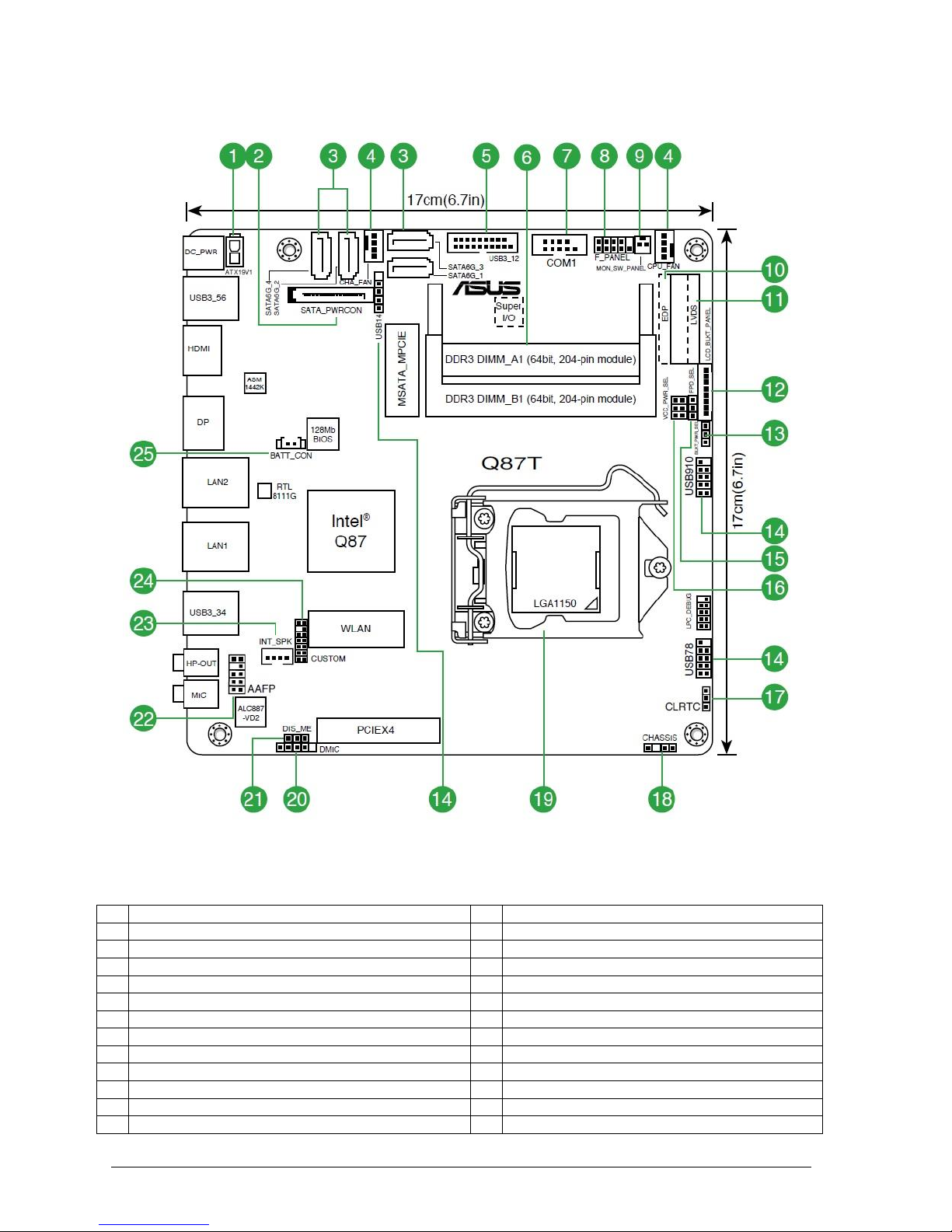
System Board Components
Figure 3: Motherboard Layout
Table 2: Motherboard Connectors
1
ATX power connector (2-pin ATX19V)
14
USB 2.0 connectors
2
SATA Power Connector
15
LVDS panel or eDP selector
3
Intel Q87 Serial ATA 6.0Gb/s connector
16
Display panel VCC power selector
4
CPU and chassis fan connectors
17
Clear RTC RAM
5
USB 3.0 connector (20-1 pin USB3_12)
18
Chassis intrusion connector
6
DDR3 SO-DIMM slots
19
Intel LGA1150 CPU socket
7
Serial port connector
20
DMIC connectors
8
System panel connector
21
Intel ME jumper
9
Display panel connector
22
Front panel audio connector
10
Embedded DisplayPort (30-pin eDP)
23
Internal stereo speaker header
11
LVDS connector (30-pin LVDS)
24
Custom header
12
Flat panel display brightness connector
25
RTC Battery header
13
Display panel backlight power selector
Page 15

V1.0 Vig820S Motherboard Manual
14
Back Panel Connectors
The Motherboard external IO connectors are attached to a metallic I/O shield. This
shield serves several purposes:
• It protects the sensitive Motherboard from any external EMC interference.
• It stops the computer from interfering with other electrical devices.
• It allows the Motherboard to be easily upgraded in the future without having to
resort to buying a whole new case. Simply change the I/O shield to match the
Motherboard.
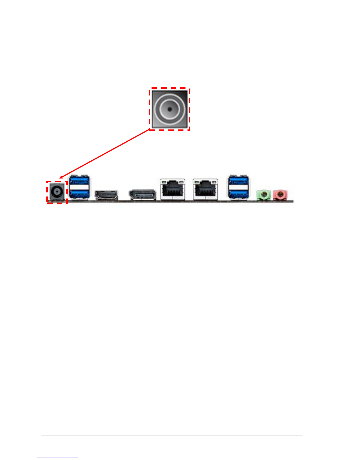
Figure 4: Back Panel Connectors
Power Jack – the board can be powered through a 19 V DC connector on the back panel.
The back panel DC connector is compatible with a 7.4 mm/OD (outer diameter) and 5.1
mm/ID (inner diameter) plug, where the inner contact is +19 (±10%) V DC and the shell is
GND. The maximum current rating is 12 A.
USB 3.0 Ports - The USB 3.0 ports are for attaching USB devices such as keyboard,
mouse, or other USB compatible devices.
LAN Ports - The standard RJ-45 LAN jacks are for connection to the Local Area Network
(LAN). You can connect a network cable to it.
DisplayPort – This port is used for to connect a DisplayPort compatible display.
HDMI Port - The High-Definition Multimedia Interface (HDMI) is an all-digital audio/video
interface capable of transmitting uncompressed streams. HDMI supports all TV format,
including standard, enhanced, or high-definition video, plus multi-channel digital audio on a
single cable.
Audio Ports - These audio connectors are used for audio devices (MIC-IN, LINE-OUT).
Note:
The back panel audio line out connectors is designed to power headphones or amplified
speakers only. Poor audio quality occurs if passive (non-amplified) speakers are connected to
this output.
Page 16

V1.0 Vig820S Motherboard Manual
15
Chapter 2: System Board Options
The Vig820S motherboard is capable of accepting Intel® Core i3, i5, i7 processors and
Intel Pentium processors. RAM can be upgraded to a maximum of 16GB using DDR3
1333MHz or 1600MHz Non ECC Unbuffered memory.
WARNING!
Unplug the system before carrying out the procedures described in this chapter.
Failure to disconnect power before you open the system can result in personal
injury or equipment damage. Hazardous voltage, current, and energy levels are
present in this product. Power switch terminals can have hazardous Voltages
present even when the power switch is off.
The procedures assume familiarity with the general terminology associated with
personal computers and with the safety practices and regulatory compliance
required for using and modifying electronic equipment.
Do not operate the system with the cover removed. Always replace the cover
before turning on the system.
As the colours of the wires in the mains lead of this computer may not correspond with the
coloured markings identifying the terminals in your plug precede as follows:
The wire which is coloured green-and-yellow must be connected to the terminal in the plug
which is marked by the letter E or by the safety Earth symbol Q or coloured green or green-
and-yellow.
The wire which is coloured blue must be connected to the terminal which is marked with the
letter N or coloured black.
The wire which is coloured brown must be connected to the terminal which is marked with the
letter L or coloured red.
CAUTION!
The Viglen Vig820S motherboard
and associated components are
sensitive electronic devices. A small
static shock from your body can
cause expensive damage to your
equipment.
Page 17

V1.0 Vig820S Motherboard Manual
16
BEFORE YOU BEGIN
Make sure you are earthed and free of static charge before you open the computer case.
If you are unsure about upgrading your computer, return it to Viglen so a qualified
engineer can perform the upgrade.
STEPS TO TAKE TO PREVENT STATIC DISCHARGE:
1. The best way to prevent static discharge is to buy an anti-static strap from your local
electrical shop. While you are wearing the strap and it is earthed, static charge will be
harmlessly bled to ground.
2. Do not remove the component from its anti-static protective packaging until you are
about to install it.
3. Hold boards by the edges - try not to touch components / interface strips etc.
NOTE: We recommend that you return your computer to the service department for
upgrading. Any work carried out is fully guaranteed. Upgrades should only be carried out
by persons who are familiar with handling IC's, as incorrect installation will invalidate the
guarantee.
Page 18
V1.0 Vig820S Motherboard Manual
17
System Board Jumper Settings
Do not move the jumper with the power on. Always turn off the power and unplug the
power cord from the computer before changing a jumper setting. Otherwise, the board
could be damaged.
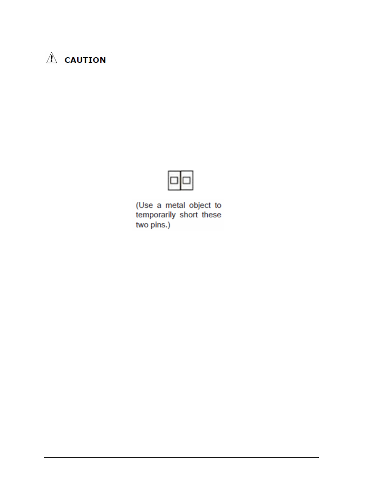
Clear CMOS Jumper: CLR_CMOS
The configuration Jumper (CLR_CMOS) allows the user to clear the CMOS. The CMOS
RAM onboard has a power supply from an external battery to keep the data of the
system configuration. The CMOS RAM allows the system to automatically boot OS every
time it is turned on.
Figure 5: Clear CMOS jumper
Page 19
V1.0 Vig820S Motherboard Manual
18
Motherboard Connectors
There are connectors on the motherboard for the Power supply, HD audio, fans, front
panel audio, front panel USB and front panel connectors. The location and/or details of
these connections are shown below.
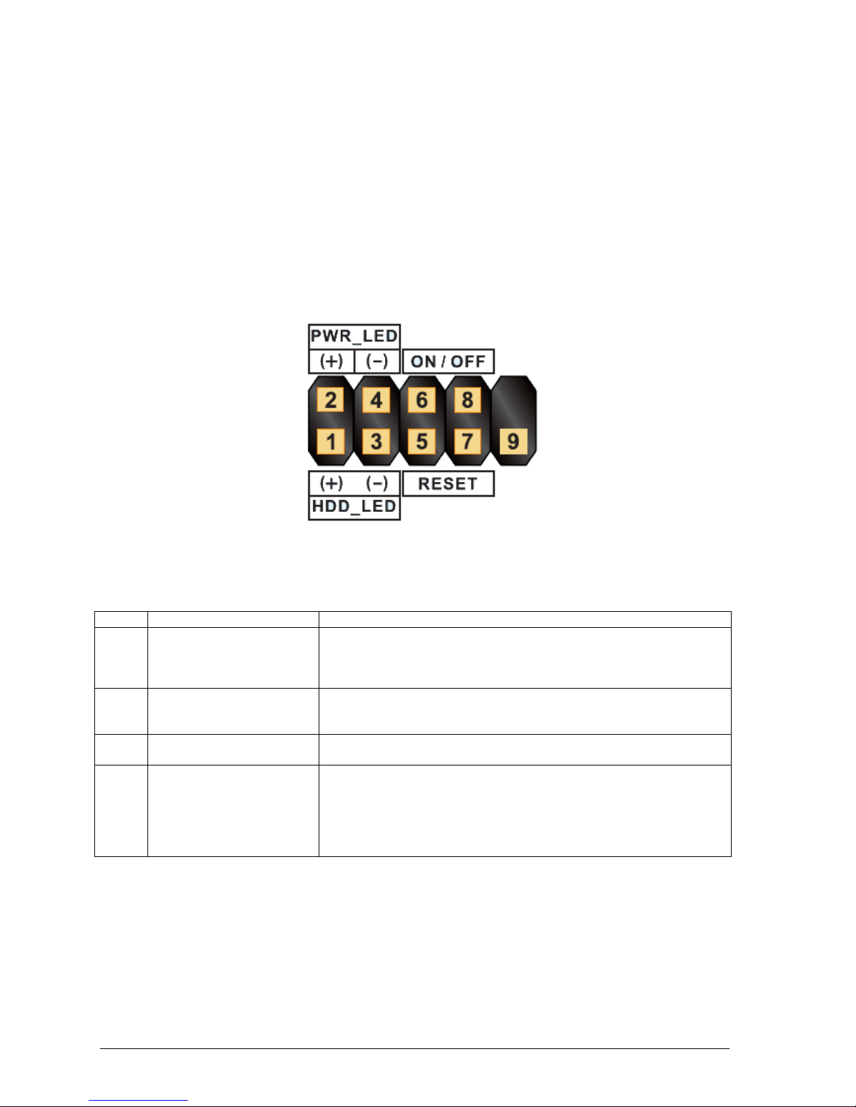
Front Panel Connectors: SYS_PANEL
These connectors are for electrical connection to the front panel switches and LEDs. The
SYS_PANEL is compliant with Intel® Front Panel I/O Connectivity Design Guide.
Figure 6: Front Panel Connectors
Table 3: Front Panel Connectors (Sys_Panel)
Pin
Connector
Comments
1-3
Hard Drive Activity LED
Header
Pins 1 and 3 can be connected to an LED to provide a visual
indicator that data is being read from or written to a hard drive.
Proper LED function requires a Serial ATA hard drive connected to
an onboard Serial ATA connector.
5-7
Reset Switch Header
Pins 5 and 7 can be connected to a momentary single pole, single
throw (SPST) type switch that is normally open. When the switch is
closed, the board resets and runs the POST.
2-4
Power/Sleep LED Header
Pins 2 and 4 can be connected to a one- or two-colour LED. This
display if the computer is active or not.
6-8
Power Switch Header
Pins 6 and 8 can be connected to a front panel momentary-contact
power switch. The switch must pull the SW_ON# pin to ground for at
least 50 ms to signal the power supply to switch on or off. (The time
requirement is due to internal debounce circuitry on the board.) At
least two seconds must pass before the power supply will recognize
another on/off signal.
Page 20
V1.0 Vig820S Motherboard Manual
19
Power Connectors
External 12V Power Connector
The board can be powered with a 12~19V DC external power supply through the 12~19V
DC connector on the back panel. The back panel connector accepts plugs with an inner
diameter of 5.5mm and an outer diameter of 7.5mm.
Figure 7: Back Panel
NOTE:
Note: DC power in can be within 12-19V (>=120W) with this motherboard. The back
panel DC connector is compatible with a 7.4 mm/OD (outer diameter) and 5.1 mm/ID
(inner diameter) plug, where the inner contact is +19 (±10%) V DC and the shell is GND.
The maximum current rating is 12 A.
Page 21

V1.0 Vig820S Motherboard Manual
20
Front Panel Audio Connector: FP_AUDIO
This connector allows you to connect the front panel audio and is compliant with Intel®
Front Panel I/O Connectivity Design Guide.
Figure 8: Front panel audio connector
Table 4: Front panel audio header for HD audio
Pin
Signal Name
Pin
Signal Name
1
[Port 1] Left channel
2
Ground
3
[Port 1] Right channel
4
PRESENCE# (Dongle present)
5
[Port 2] Right channel
6
[Port 1] SENSE_RETURN
7
SENSE_SEND (Jack detection)
8
Key (no pin)
9
[Port 2] Left channel
10
[Port 2] SENSE_RETURN
Page 22
V1.0 Vig820S Motherboard Manual
21
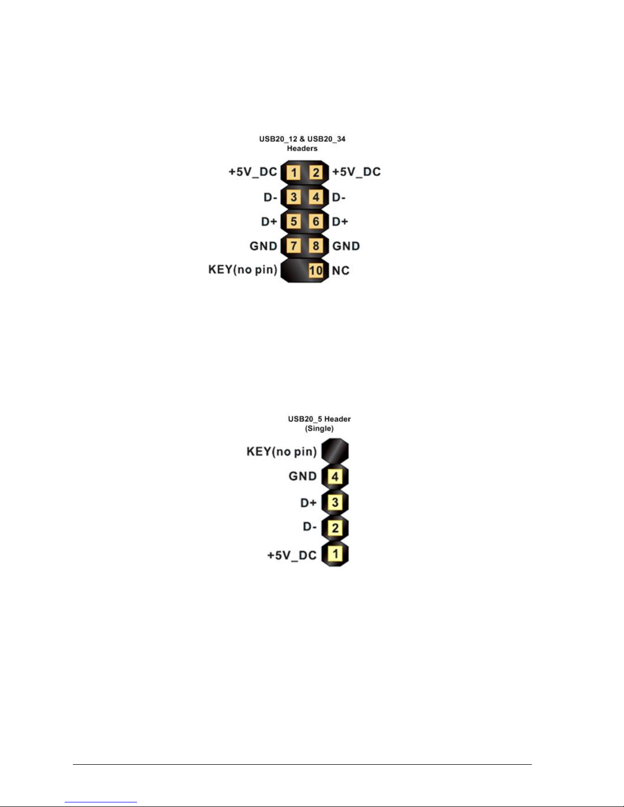
Front USB Connector: USB20_34, USB20_12
This connector, compliant with Intel® I/O Connectivity Design Guide, is ideal for
connecting high-speed USB interface peripherals such as USB HDD, digital cameras,
MP3 players, printers, modems and the like.
Figure 9: Front USB connectors
Front USB Connector: USB20_5
Figure 10: Front USB connector - single
Page 23
V1.0 Vig820S Motherboard Manual
22
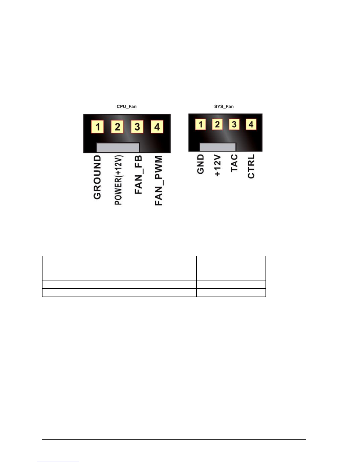
Fan Power Connectors: CPU_FAN, SYS_FAN
The fan power connectors support system cooling fan with +12V. When connecting the
wire to the connectors, always note that the red wire is the positive and should be
connected to the +12V; the black wire is Ground and should be connected to GND. The
motherboard has a System Hardware Monitor chipset on-board, which must be used with
fans specially designed with speed sensors to take advantage of the CPU fan control.
Figure 11: Fan Power connectors
Table 5: System FAN header, CPU FAN header
PIN
4-Wire support
PIN
3-Wire support
1
GND
1
GND
2
+12V power
2
+12V power
3
FAN_FB
3
TAC
4
FAN_PWM
4
Control
Page 24
V1.0 Vig820S Motherboard Manual
23
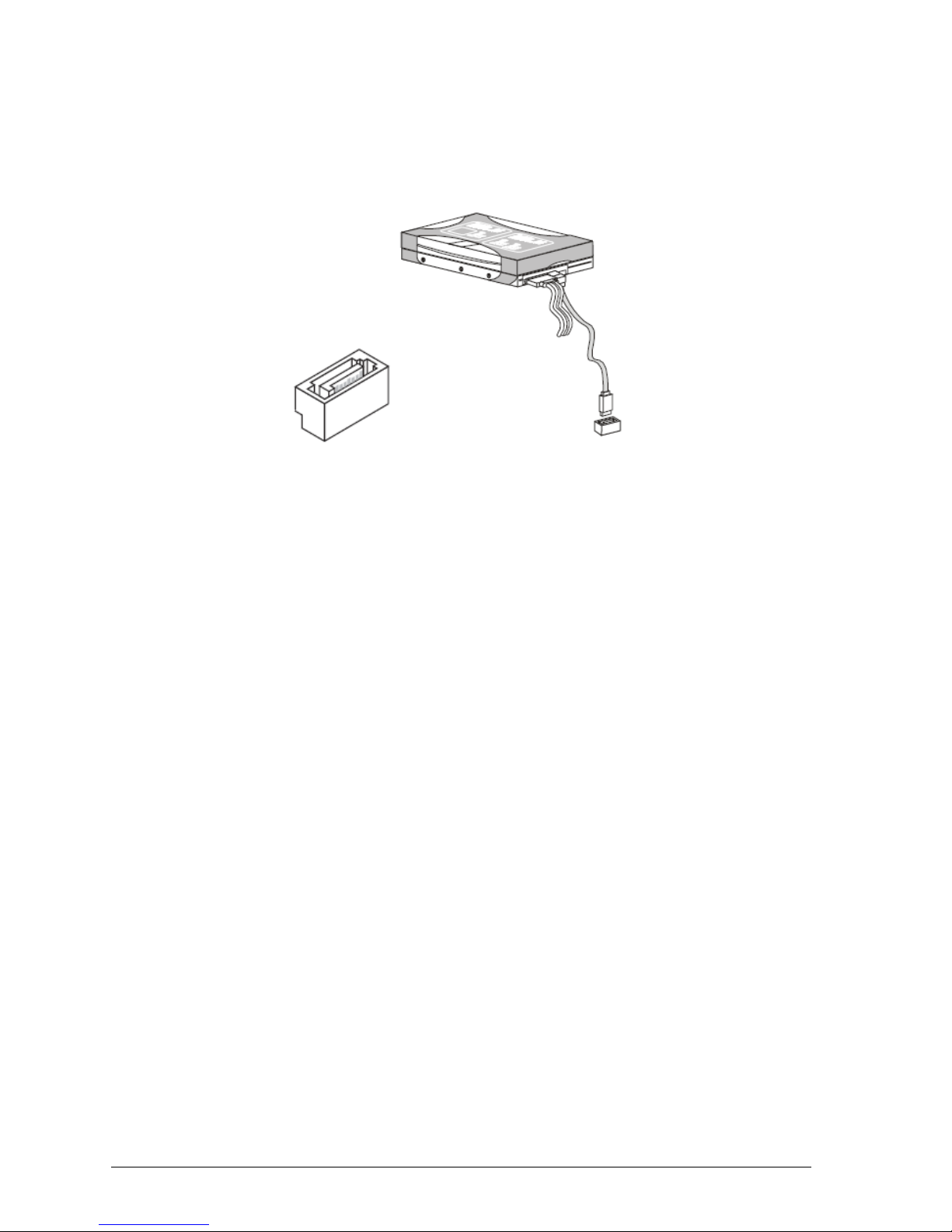
Serial ATA Connector: SATA0, SATA1
This connector is a high-speed Serial ATA interface port. Each connector can connect to
one Serial ATA device.
Figure 12: Serial ATA Connector
NOTE:
Please do not fold the serial ATA cable into 90-degree angle. Otherwise, data loss may
occur during transmission.
Page 25
V1.0 Vig820S Motherboard Manual
24
Upgrading the CPU
CAUTION!
Before installing or removing a processor, make sure the AC power has been removed
by unplugging the power cord from the computer; the standby power LED should not be
lit. Failure to do so could damage the processor and the board.
To install a processor, follow these instructions:
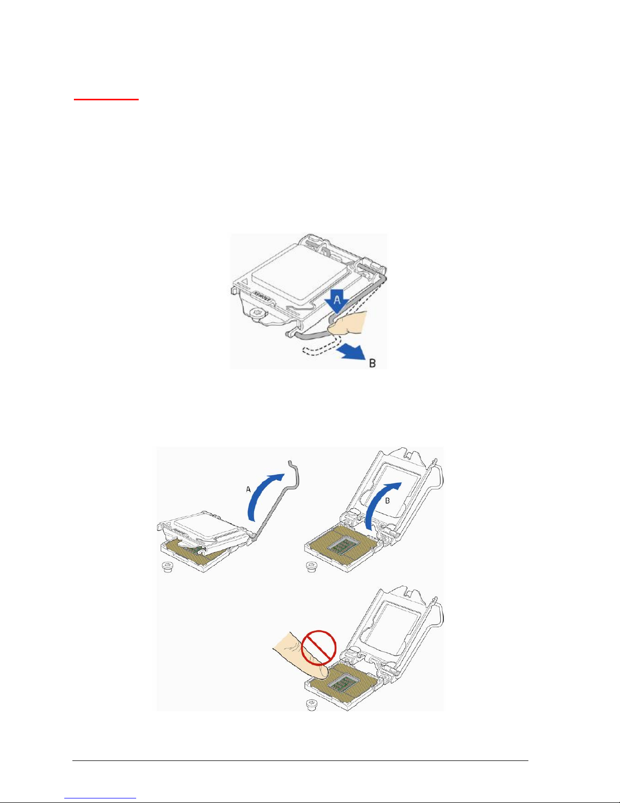
1. Unlatch the processor socket lever by pushing it down and away from the socket.
(Figure 13, A, B)
Figure 13: Unlatch the socket lever
2. Rotate the socket lever to lift the load plate away from the socket (Figure 14, A).
Make sure that the load plate is in the fully open position (Figure 14, B) while being
careful not to damage adjacent components. Do not touch the socket contacts.
Figure 14: Lift the load plate
Page 26
V1.0 Vig820S Motherboard Manual
25
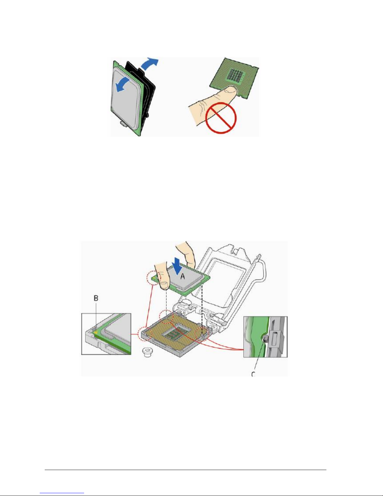
3. Remove the processor from its protective cover. Hold the processor only at the
edges, being careful not to touch the bottom of the processor (see Figure 15).
Figure 15: Remove the processor from the protective cover
Note: Do not discard the processor cover. Always replace the processor cover if you
remove the processor from the socket.
4. Hold the processor with your thumb and index finger oriented as shown in Figure 16
to align your fingers with the socket finger cut-outs. Make sure that the processor Pin
1 indicator (gold triangle) is aligned with the Pin 1 chamfer on the socket (Figure 16,
B) and that the notches on the processor align with the posts on the socket (Figure
16, C). Lower the processor straight down without tilting or sliding it in the socket
(Figure 16, A).
Figure 16: Install the processor
Page 27

V1.0 Vig820S Motherboard Manual
26
5. Carefully lower the socket lever (Figure 17, A) while making sure that the front edge
of the load plate slides under the shoulder screw cap as the lever is lowered. Latch
the socket lever under the load plate tab (Figure 17, C, and D). The socket cover
(Figure 17, B) will pop off as shown.
Figure 17: Secure the load plate in place
6. Pick up the socket cover and remove it from the desktop board.
Page 28

V1.0 Vig820S Motherboard Manual
27
Connecting the Processor Fan Heat Sink Cable
Connect the processor fan heat sink power cable to the 4-pin processor fan header (see
Figure 18).
Make sure the four hooks are in the proper position before you install the cooler.
If the heatsink is held in by screws, position heatsink correctly and screw into place.
Figure 18: Connecting the processor fan heat sink power cable to the processor fan header
Page 29

V1.0 Vig820S Motherboard Manual
28
Installing & Removing Memory Modules
Installing Memory
You can install up to 8GB of memory in each of the motherboard SO-DIMM sockets. The
motherboard has two SO-DIMM sockets. The motherboard supports the following
memory features:
o Two DDR3 SO-DIMMs with gold-plated contacts.
o Non-ECC (64-bit) memory.
o 1GB, 2GB, 4GB and 8GB modules.
o Memory Speeds 1333MHz & 1600MHz
To install SO-DIMMs, follow these steps:
1. Observe the precautions in “Before You Begin”. Turn off the computer and all
Peripheral devices.
2. Remove the computer cover and locate the DIMM sockets.
3. Holding the SO-DIMM by the edges, remove it from its antistatic package.
4. Position the SO-DIMM above the socket. Align the two small notches in the bottom
edge of the SO-DIMM with the socket tabs. Insert the bottom edge of the SO-DIMM
into the socket.
5. When the SO-DIMM is seated, push down until the retaining arms at either ends of
the socket snap into place. Make sure the clips are firmly in place.
6. Replace the computer cover.
Figure 19: Memory Installation
Page 30

V1.0 Vig820S Motherboard Manual
29
Removing Memory
To remove a SO-DIMM, follow these steps:
1. Observe the precautions in "Before You Begin”.
2. Turn off all peripheral devices connected to the computer. Turn off the computer.
3. Remove the computer cover.
4. Gently spread the retaining arms at each end of the socket. The SO-DIMM pops out
of the socket. Hold the SO-DIMM by the edges, lift it away from the socket, and store
it in an antistatic package.
5. Reinstall and reconnect any parts you removed or disconnected to reach the SO-
DIMM sockets.
Figure 20: Removing Memory Modules
Page 31

V1.0 Vig820S Motherboard Manual
30
Replacing the Clock/CMOS RAM Battery
A lithium battery is installed in a socket on the system board.
The battery has an estimated life expectancy of seven years. When the battery starts to
weaken, it loses voltage; when the voltage drops below a certain level, the system
settings stored in CMOS RAM (for example, the date and time) may be wrong.
If the battery fails, you will need to replace it with a CR2032 battery or an equivalent. As
long as local ordinance permits, you may dispose of individual batteries as normal
rubbish. Do not expose batteries to excessive heat or any naked flame. Keep all
batteries away from children.
CAUTION!
Danger of explosion if the battery is incorrectly replaced. Replace only with the same or
equivalent type recommended by Viglen. Discard used batteries according to
manufacturer’s instructions.
To replace the battery, carry out the following:
1. Observe the precautions in “Before You Begin.”
2. Turn off all peripheral devices connected to the system.
3. Turn off the system.
4. Remove any components that are blocking access to the battery.
5. Figure 21 shows the battery location. Gently pry the battery free from its socket.
6. Install the new battery in the socket.
Figure 21: Removing the Battery
Page 32

V1.0 Vig820S Motherboard Manual
31
Chapter 3: Solving Problems
The first part of this chapter helps you identify and solve problems that might occur when
the system is in use. The second part lists error code messages that might be displayed.
Please remember that if you cannot solve the problem by yourself then you should
contact Viglen Technical Support for further assistance.
Viglen Technical Support can be reached in the following ways:
Telephone: 01727 201 850
Fax: 01727 201 858
Email: techsupport@viglen.co.uk
You can also look for support information on our web site:
http://www.viglen.co.uk
Device drivers and various useful utilities can be downloaded from our ftp site:
http://download.viglen.co.uk/files/
Resetting the System
Before checking your system for hardware problems, it is always a good idea to try
resetting your computer and see if a re-boot can solve the problem. Most software
related problems can be solved simply by re-booting your PC.
Table 6: Resetting the System
To do the following
Press
Soft boot: Clear the system memory and
reload the operating system (also called
warm reset).
<Ctrl + Alt + Del>
Cold boot: Clear the system memory, halt
power to all peripherals, restart POST, and
reload the operating system.
Power off/on or reset button (at front
of the system)
Page 33

V1.0 Vig820S Motherboard Manual
32
Troubleshooting Procedures
This section provides a step-by-step troubleshooting procedure to identify a problem and
locate its source.
CAUTION!
1. Turn off the system and any peripheral devices before you disconnect any peripheral
cables from the system. Otherwise, you can permanently damage the system or the
peripheral devices.
2. Make sure the system is plugged into a properly grounded power outlet.
3. Make sure your keyboard and video display are correctly connected to the system.
Turn on the video display, and turn up its brightness and contrast controls to at least
two-thirds of the maximum (refer to the documentation supplied with the video
display).
4. If the operating system normally loads from the hard disk drive, make sure there is no
diskette in the diskette drive. If the operating system normally loads from a diskette,
insert the operating system diskette into the drive.
5. Turn on the system. If the power indicator does not light, but the system seems to be
operating normally, the indicator is probably defective. Monitor the power-on self test
(POST) execution. Each time you turn on the system, the POST checks the system
board, memory, keyboard, and certain peripheral devices.
NOTE: If the POST does not detect any errors, the system beeps once and boots up.
Errors that do not prevent the boot process (non-fatal errors) display a message that
looks similar to the following:
Error Message Line 1
Error Message Line 2
Press <DEL> for Set-up, <F1> to Boot
You can note the error and press <F1> to resume the boot-up process, or <DEL>
to enter Set-up.
Errors that prevent the boot process from continuing (fatal errors), are communicated by
a series of audible beeps. If this type of error occurs, refer to the error codes and
messages listed at the end of this chapter.
6. Confirm that the operating system has loaded.
Page 34

V1.0 Vig820S Motherboard Manual
33
Problems & Suggestions
Table 7: Problems and Suggestions
What happens
What to do
Application software
problems
Try resetting the system.
Make sure all cables are installed correctly.
Verify that the system board jumpers are set properly.
Verify that your system hardware configuration is set correctly. In
Setup, check the values against the system settings you recorded
previously. If an error is evident (wrong type of drive specified, for
example), make the change in Setup and reboot the system. Record
your change.
Make sure the software is properly configured for the system. Refer to
the software documentation for information.
Try a different copy of the software to see if the problem is with the
copy you are using.
If other software runs correctly on the system, contact the vendor of
the software that fails.
If you check all of the above with no success, try clearing CMOS
RAM and reconfiguring the system. Make sure you have your list of
system settings available to re-enter, because clearing CMOS RAM
sets the options to their default values.
Characters onscreen are distorted
or incorrect
Make sure the brightness and contrast controls are properly adjusted
on the monitor.
Make sure the video signal cable and power cables are properly
installed.
Make sure your monitor is compatible with the video mode you have
selected.
Characters do not
appear on screen
Make sure the video display is plugged in and turned on.
Check that the brightness and contrast controls are properly adjusted.
Check that the video signal cable is properly installed.
Make sure a video board is installed, enabled, and the jumpers are
positioned correctly.
Reboot the system.
Page 35

V1.0 Vig820S Motherboard Manual
34
Table 8: Problems and Suggestions (Continued)
What happens
What to do
CMOS RAM settings
are wrong
If system settings stored in CMOS RAM change for no apparent
reason (for example, the time of day develops an error), the backup
battery may no longer have enough power to maintain the settings.
Replace the battery (Chapter 2).
Diskette drive light
does not go on when
drive is in use or is
tested by POST
Make sure the power and signal cables for the drive are properly
installed.
Check that the drive is properly configured and enabled in Setup.
Hard drive light does
not go on when drive
is in use or is tested
by POST
Make sure the power and signal cables for the drive are properly
installed.
Make sure the front panel connector is securely attached to the
system board headers.
Check that the drive is properly configured and enabled in Setup.
Check the drive manufacturer's manual for proper configuration for
remote hard disk drive activity.
Power-on light does
not go on
If the system is operating normally, check the connector between the
system board and the front panel. If OK, the light may be defective.
Prompt doesn't
appear after system
boots
It’s probably switched off.
A serious fault may have occurred consult your dealer service
department / Technical Support.
Setup, can't enter
If you can't enter Setup to make changes, check the switch that
disables entry into Setup (Chapter 2). If the switch is set to allow
entry into Setup, you might need to clear CMOS RAM to the default
values and reconfigure the system in Setup.
System halts before
completing POST
This indicates a fatal system error that requires immediate service
attention. Note the screen display and write down any beep code
emitted. Provide this information to your dealer service department /
Technical Support.
Page 36

V1.0 Vig820S Motherboard Manual
35
Chapter 4: System BIOS
4.1 What is the BIOS?
The BIOS (Basic Input Output System) is an important piece of software which is stored
in a ROM (Read Only Memory) chip inside the computer. It consists of the basic
instructions for controlling the disk drives, hard disk, keyboard and serial/parallel ports.
The BIOS also keeps a list of the specifications of the computer in battery-backed RAM
(also known as the CMOS RAM) and provides a special Setup program to change this
information.
The BIOS in your Viglen computer is guaranteed to be fully compatible with the IBM
BIOS. It has been written by American Megatrends Inc, an industrial leader in the field of
BIOS software.
4.2 The Power-On sequence
When the computer is first switched on, certain instructions in the BIOS are executed to
test various parts of the machine. This is known as the POST (Power-On Self Test)
routine. When you switch the computer on (or when you press the Reset button or press
<Ctrl> + <Alt>+ <Delete> keys, which has the same effect), you can see on the monitor
that it counts through the memory, testing it. The floppy disk drives are then accessed
and tested, and the various interfaces are checked. If there are any errors, a message is
displayed on the screen.
Page 37

V1.0 Vig820S Motherboard Manual
36
4.3 Managing and Updating BIOS
There are up three methods of updating BIOS to the latest Viglen approved version.
The number of options made available for any particular board may vary depending on
BIOS Support, drive support and BIOS update file size. You only need to use one.
BIOS Updater
EZ-Flash 2 Update
BIOS recovery
Latest BIOS files and Utility are available from Viglen FTP site:
http://download.viglen.co.uk/files/Motherboards/Vig820s
NOTE: Please review the instructions distributed with the upgrade utility before
attempting a BIOS upgrade.
4.3.1 BIOS Update Instructions under DOS
The BIOS Updater allows you to update BIOS in a DOS environment. This utility also allows you to copy
the current BIOS file that you can use as a backup when the BIOS fails or gets corrupted during the
updating process.
1. Save BIOS update zipped file to a temporary directory.
2. Extract the necessary files.
3. Copy the contents of the file to a bootable USB key or CD-ROM media.
4. Boot the target PC with the device connected or inserted.
5. Select <F8> during POST to display the Boot Menu and select your bootable device.
6. At the DOS prompt Type 'Flash.bat' to launch the BIOS updates process.
7. Reboot the system once complete.
8. Enter the BIOS Setup and Ensure to load the BIOS default settings to ensure system compatibility and
stability. Select the Load Optimized Defaults item under the Exit menu.
DO NOT shutdown or reset the system while updating the BIOS! Doing so may cause
system boot failure!
Page 38

V1.0 Vig820S Motherboard Manual
37
4.3.2 BIOS Update Instructions using EZ-Flash Method
For this method you will require a Flash USB device and required BIOS file.
1. Insert the USB flash disk that contains the latest BIOS file to the USB port.
2. Enter the Advanced Mode of the BIOS setup program. Go to the Tool menu to select ASUS EZ Flash
Utility and press <Enter> to enable it.
3. Press <Tab> to switch to the Drive field.
4. Press the Up/Down arrow keys to find the USB flash disk that contains the latest BIOS, and then press
<Enter>.
5. Press <Tab> to switch to the Folder Info field.
6. Press the Up/Down arrow keys to find the BIOS file, and then press <Enter> to perform the BIOS
update process. Reboot the system when the update process is done.
Note:
• This function supports USB flash disks formatted using FAT32/16 on a single partition only.
• Ensure to load the BIOS default settings to ensure system compatibility and stability. Select
the Load Optimized Defaults item under the Exit menu. .
IMPORTANT!!!!!
During the update process DO NOT shut down the PC or interrupt the process, this could
cause damage to the motherboard.
Figure 22: EZ Flash BIOS update screen
Page 39

V1.0 Vig820S Motherboard Manual
38
4.3.3 Recovering the BIOS - CrashFree BIOS 3
The CrashFree BIOS 3 is an auto recovery tool that allows you to restore the BIOS file when it fails or gets
corrupted during the updating process. You can restore a corrupted BIOS file using the motherboard
support DVD or a USB flash drive that contains the updated BIOS file.
Before using this utility, rename the BIOS file in the removable device to:
Q87T.CAP.
To recover the BIOS:
1. Turn on the system.
2. Insert the support DVD to the optical drive or the USB flash drive that contains the BIOS file to the
USB port.
3. The utility automatically checks the devices for the BIOS file. When found, the utility reads the
BIOS file and enters ASUS EZ Flash 2 utility automatically.
4. The system requires you to enter BIOS Setup to recover BIOS settings. To ensure system
compatibility and stability, we recommend that you press <F5> to load default BIOS values.
DO NOT shut down or reset the system while updating the BIOS! Doing so can cause system boot
failure!
Page 40

V1.0 Vig820S Motherboard Manual
39
4.4 BIOS Setup
This chapter provides basic information on the BIOS Setup program and allows you to
configure the system for optimum use. You may need to run the Setup program when:
An error message appears on the screen during the system booting up, and requests
you to run BIOS SETUP.
You want to change the default settings for customized features.
Note: The items under each BIOS category described in this chapter are under
continuous update for better system performance. Therefore, the description may be
slightly different from the latest BIOS and should be held for reference only.
Entering BIOS Setup
Power on the computer and the system will start POST (Power On Self Test) process.
When the message below appears on the screen, press <F2> or <DEL> key to enter
Setup. You can also press <F8> when the message below is on screen to bring up the
Boot Menu.
“Press <Del> or <F2> to enter BIOS setup Menu”
If the message disappears before you respond and you still wish to enter Setup, restart
the system by turning it OFF and On or pressing the RESET button. You may also restart
the system by simultaneously pressing <Ctrl>, <Alt>, and <Delete> keys.
Control Keys
Figure 23: BIOS control keys
After entering the BIOS, the first screen you will see is the Main Menu – EZ Mode
Page 41

V1.0 Vig820S Motherboard Manual
40
BIOS menu screen
The BIOS setup program can be used under two modes: EZ Mode and Advanced
Mode. You can change modes from the Exit menu or from the Exit/Advanced Mode
button in the EZ Mode/Advanced Mode screen.
EZ Mode
By default, the EZ Mode screen appears when you enter the BIOS setup program. The
EZ Mode provides you an overview of the basic system information, and allows you to
select the display language, system performance mode and boot device priority. To
access the Advanced Mode, click Exit/Advanced Mode, then select Advanced Mode or
press F7 for the advanced BIOS settings
Figure 24: BIOS Main Menu – EZ Mode
• The boot device options vary depending on the devices you installed to the system.
• The Boot Menu (F8) button is available only when the boot device is installed to the
system.
Page 42

V1.0 Vig820S Motherboard Manual
41
Advanced Mode
The Advanced Mode provides advanced options for experienced end-users to configure
the BIOS settings. The figure below shows an example of the Advanced Mode. Refer to
the following sections for the detailed configurations.
Figure 25: BIOS Main Menu – Advanced Mode
BIOS Main Menu selection
The menu bar on top of the screen has the following main items:
Page 43

V1.0 Vig820S Motherboard Manual
42
Menu items
The highlighted item on the menu bar displays the specific items for that menu. For
example, selecting Main shows the Main menu items.
The other items (Ai Tweaker, Advanced, Monitor, Boot, Tool, and Exit) on the menu bar
have their respective menu items
4.5 My Favourites
MyFavorites is your personal space where you can easily save and access your favourite
BIOS items.
Figure 26: My Favourites Menu
Page 44

V1.0 Vig820S Motherboard Manual
43
4.6 Main Menu
The Main menu screen appears when you enter the Advanced Mode of the BIOS Setup
program. The Main menu provides you an overview of the basic system information, and
allows you to set the system date, time, language, and security settings.
Figure 27: Main Menu
4.6.1 System Language [English]
Allows you to choose the BIOS language version from the options.
4.6.2 System Date [Day xx/xx/xxxx]
Allows you to set the system date.
4.6.3 System Time [xx:xx:xx]
Allows you to set the system time.
Page 45

V1.0 Vig820S Motherboard Manual
44
4.6.4 Security
The Security menu items allow you to change the system security settings.
If you have forgotten your BIOS password, erase the CMOS Real Time Clock (RTC) RAM to clear
the BIOS password.
The Administrator or User Password items on top of the screen show the default Not Installed.
After you set a password, these items show Installed.
Administrator Password
If you have set an administrator password, we recommend that you enter the administrator password for
accessing the system. Otherwise, you might be able to see or change only selected fields in the BIOS
setup program.
To set an administrator password:
1. Select the Administrator Password item and press <Enter>.
2. From the Create New Password box, key in a password, then press <Enter>.
3. Confirm the password when prompted.
To change an administrator password:
1. Select the Administrator Password item and press <Enter>.
2. From the Enter Current Password box, key in the current password, then press <Enter>.
3. From the Create New Password box, key in a new password, then press <Enter> Confirm the
password when prompted.
To clear the administrator password, follow the same steps as in changing an administrator password, but
press <Enter> when prompted to create/confirm the password. After you clear the password, the
Administrator Password item on top of the screen shows Not Installed.
User Password
If you have set a user password, you must enter the user password for accessing the system. The User
Password item on top of the screen shows the default Not Installed. After you set a password, this item
shows Installed.
To set a user password:
1. Select the User Password item and press <Enter>.
2. From the Create New Password box, key in a password, then press <Enter>.
3. Confirm the password when prompted.
To change a user password:
1. Select the User Password item and press <Enter>.
2. From the Enter Current Password box, key in the current password, then press <Enter>.
3. From the Create New Password box, key in a new password, then press <Enter>.
4. Confirm the password when prompted.
To clear the user password, follow the same steps as in changing a user password, but press<Enter>
when prompted to create/confirm the password. After you clear the password, the User Password item on
top of the screen shows Not Installed.
Page 46

V1.0 Vig820S Motherboard Manual
45
4.7 AI Tweaker Menu
The Ai Tweaker menu items allow you to configure overclocking-related items.
Be cautious when changing the settings of the Ai Tweaker menu items. Incorrect field values can cause the
system to malfunction.
The configuration options for this section vary depending on the CPU and DIMM model installed on the
motherboard.
Figure 28: Ai Tweaker Menu
Scroll down to display the following items:
Figure 29: Tweaker Menu
Page 47

V1.0 Vig820S Motherboard Manual
46
Scroll down to display the following items:
Figure 30: Tweaker Menu
Target CPU Turbo-Mode Speed : xxxxMHz
Displays the target CPU Turbo-Mode speed.
Target DRAM Speed : xxxxMHz
Displays the target DRAM speed.
Target Cache Speed : xxxxMHz
Displays the target Cache speed.
Target DMI/PEG Clock : xxxxMHz
Displays the target DMI/PEG clock.
Target iGPU Speed : xxxxMHz
Displays the target iGPU speed.
4.7.1 Ai Overclock Tuner [Manual]
Allows you to select the CPU overclocking options to achieve the desired CPU internal frequency. Select
any of these preset overclocking configuration options:
[Auto] Loads the optimal settings for the system.
[Manual] Allows you to individually set overclocking parameters.
[X.M.P.] If you install memory modules supporting the eXtreme Memory Profile
(X.M.P.) Technology, choose this item to set the profiles supported by your memory
modules for optimizing the system performance.
4.7.2 ASUS MultiCore Enhancement [Auto]
[Auto] Default set to [Auto] for maximum performance under
XMP/Manual/Userdefinedmemory frequency mode.
[Disabled] Allows you to set to default core ratio settings.
Page 48

V1.0 Vig820S Motherboard Manual
47
4.7.3 CPU Core Ratio [Auto]
Allows you to set the CPU core ratio automatically or manually.
[Auto] Sets all CPU Core Ratio to Intel® CPU default settings automatically.
[Sync All Cores] Allows you to set CPU Core Ratio settings for all cores.
[Per Core] Allows you to set CPU Core Ratio individually.
The following two items appear only when you set the CPU Core Ratio to [Sync All Cores] or [Per Core].
1-Core Ratio Limit [Auto]
Allows you to set the 1-Core Ratio Limit. Select [Auto] to apply the CPU default Turbo Ratio setting
or manually assign a 1-Core Ratio Limit value that is higher than or equal to the 2-Core Ratio Limit.
2-Core Ratio Limit [Auto]
This item becomes configurable only when you set CPU Core Ratio to [Per Core] and allows you
to set the 2-Core Ratio Limit. Select [Auto] to apply the CPU default Turbo Ratio setting or
manually assign a 2-Core Ratio Limit value that is higher than or equal to the 3-Core Ratio Limit. 1Core Limit must not be set to [Auto].
3-Core Ratio Limit [Auto]
This item becomes configurable only when you set CPU Core Ratio to [Per Core] and allows you
to set the 3-Core Ratio Limit. Select [Auto] to apply the CPU default Turbo Ratio setting or
manually assign a 3-Core Ratio Limit value that is higher than or equal to the 4-Core Ratio Limit. 1Core/2-Core Ratio Limit must not be set to [Auto].
4-Core Ratio Limit [Auto]
This item becomes configurable only when you set CPU Core Ratio to [Per Core] and allows you
to set the 4 Core Ratio Limit. Select [Auto] to apply the CPU default Turbo Ratio setting or
manually assign a 4-Core Ratio Limit value that is higher than or equal to the 3-Core Ratio Limit. 1Core/2-Core/3-Core Limit must not be set to [Auto].
4.7.4 Min CPU Cache Ratio [Auto]
Allows you to set the uncore ratio of the processor to its possible minimum value.
Configuration options: [Auto] [1] ~ [30].
4.7.5 Max CPU Cache Ratio [Auto]
Allows you to set the uncore ratio of the processor to its possible maximum value.
Configuration options: [Auto] [1] ~ [30].
4.7.6 CPU bus speed : DRAM speed ratio mode [Auto]
Allows you to set the BCLK frequency to DRAM frequency ratio.
[Auto] DRAM frequency is set to the optimized settings.
[100:133] The BCLK frequency to DRAM frequency ratio is set to 100:133.
[100:100] The BCLK frequency to DRAM frequency ratio is set to 100:100.
4.7.7 Memory Frequency [Auto]
Allows you to set the memory operating frequency. Configuration options: [DDR3-800MHz][DDR31066MHz][DDR3-1333MHz][DDR3-1600MHz][DDR3-1866MHz][DDR3-2133MHz]~[DDR3-3200MHz]
4.7.8 CPU Graphics Max. Ratio [Auto]
Allows you to set the CPU Graphics maximum ratio. The maximum ratio is 60x. Use
<+>/<-> to adjust the value.
Page 49

V1.0 Vig820S Motherboard Manual
48
4.7.9 GPU Boost [As is]
Allows you to enable the GPU Boost to accelerate the integrated GPU for extreme graphics performance.
Configuration options: [As is] [Enabled].
4.7.10 EPU Power Saving Mode [Disabled]
Allows you to enable or disable the EPU power saving function. Configuration options:
[Disabled] [Enabled]
4.7.11 DRAM Timing Control
The subitems in this menu allow you to set the DRAM timing control features. Use the <+> and <-> keys to
adjust the value. To restore the default setting, type [auto] using the keyboard and press the <Enter> key.
Primary Timings
DRAM CAS# Latency [Auto]
Configuration options: [Auto] [1 DRAM Clock] – [31 DRAM Clock]
DRAM RAS# to CAS# Delay [Auto]
Configuration options: [Auto] [1 DRAM Clock] – [31 DRAM Clock]
DRAM RAS# PRE Time [Auto]
Configuration options: [Auto] [1 DRAM Clock] – [31 DRAM Clock]
DRAM RAS# ACT Time [Auto]
Configuration options: [Auto] [1 DRAM Clock] – [63 DRAM Clock]
DRAM COMMAND Rate [Auto]
Configuration options: [Auto] [1 DRAM Clock] [2 DRAM Clock] [3 DRAM Clock]
Secondary Timings
DRAM RAS# to RAS# Delay [Auto]
Configuration options: [Auto] [1 DRAM Clock] – [15 DRAM Clock]
DRAM REF Cycle Time [Auto]
Configuration options: [Auto] [1 DRAM Clock] – [511 DRAM Clock]
DRAM Refresh Interval [Auto]
Configuration options: [Auto] [1 DRAM Clock] – [65535 DRAM Clock]
DRAM WRITE Recovery Time [Auto]
Configuration options: [Auto] [1 DRAM Clock] – [16 DRAM Clock]
DRAM READ to PRE Time [Auto]
Configuration options: [Auto] [1 DRAM Clock] – [15 DRAM Clock]
DRAM FOUR ACT WIN Time [Auto]
Configuration options: [Auto] [1 DRAM Clock] – [255 DRAM Clock]
DRAM WRITE to READ Delay [Auto]
Configuration options: [Auto] [1 DRAM Clock] – [15 DRAM Clock]
DRAM CKE Minimum pulse width [Auto]
Configuration options: [Auto] [1 DRAM Clock] – [15 DRAM Clock]
DRAM CAS# Write Latency [Auto]
Configuration options: [Auto] [1 DRAM Clock] – [31 DRAM Clock]
RTL IOL control
DRAM RTL initial Value [Auto]
Configuration options: [Auto] [1 DRAM Clock] – [63 DRAM Clock]
DRAM RTL (CHA) [Auto]
Configuration options: [Auto] [1 DRAM Clock] – [63 DRAM Clock]
Page 50

V1.0 Vig820S Motherboard Manual
49
DRAM RTL (CHB) [Auto]
Configuration options: [Auto] [1 DRAM Clock] – [63 DRAM Clock]
DRAM I0-L (CHA) [Auto]
Configuration options: [Auto] [Delay 1 Clock] - [Delay 15 Clock]
DRAM IO-L (CHB) [Auto]
Configuration options: [Auto] [Delay 1 Clock] - [Delay 15 Clock]
Third Timings
tRDRD [Auto]
Configuration options: [Auto] [1 DRAM Clock] – [7 DRAM Clock]
tRDRD_dr [Auto]
Configuration options: [Auto] [1 DRAM Clock] – [15 DRAM Clock]
tRDRD_dd [Auto]
Configuration options: [Auto] [1 DRAM Clock] – [15 DRAM Clock]
tWRRD [Auto]
Configuration options: [Auto] [1 DRAM Clock] – [63 DRAM Clock]
tWRRD_dr [Auto]
Configuration options: [Auto] [1 DRAM Clock] – [15 DRAM Clock]
tWRRD_dd [Auto]
Configuration options: [Auto] [1 DRAM Clock] – [15 DRAM Clock]
tWRWR [Auto]
Configuration options: [Auto] [1 DRAM Clock] – [7 DRAM Clock]
tWRWR_dr [Auto]
Configuration options: [Auto] [1 DRAM Clock] – [15 DRAM Clock]
tWRWR_dd [Auto]
Configuration options: [Auto] [1 DRAM Clock] – [15 DRAM Clock]
Dec_WRD [Auto]
Configuration options: [Auto] [0] [1]
tRDWR [Auto]
Configuration options: [Auto] [1 DRAM Clock] – [31 DRAM Clock]
tRDWR_dr [Auto]
Configuration options: [Auto] [1 DRAM Clock] – [31 DRAM Clock]
tRDWR_dd [Auto]
Configuration options: [Auto] [1 DRAM Clock] – [31 DRAM Clock]
MISC
MRC Fast Boot [Enabled]
Allows you to enable or disable the MRC fast boot.
[Enabled] Enables the MRC fast boot.
[Disable] Disables the MRC fast boot.
DRAM CLK Period [Auto]
Configuration options: [Auto] [1] – [14]
Channel A DIMM Control [Enable Bot...]
Configuration options: [Enable Both DIMMS] [Disable DIMM0] [Disable DIMM1]
[Disable Both DIMMS]
Page 51

V1.0 Vig820S Motherboard Manual
50
Channel B DIMM Control [Enable Bot...]
Configuration options: [Enable Both DIMMS] [Disable DIMM0] [Disable DIMM1]
[Disable Both DIMMS]
Scrambler Setting [Optimized ...]
Configuration options: [Optimized (ASUS)] [Default (MRC)]
4.7.12 DIGI+ VRM
CPU Load-Line Calibration [Auto]
Load-line is defined by Intel VRM specification and affects CPU voltage. The CPU working voltage will
decrease proportionally to CPU loading. Higher value gets a higher voltage and better overclocking
performance, but increases the CPU and VRM thermal conditions. This item allows you to adjust the
voltage range from the following percentages to boost the system performance: 0% (Regular), 25%
(Medium), 50% (High), 75% (Ultra High), and 100% (Extreme). Configuration options: [Auto] [Regular]
[Medium] [High] [Ultra High] [Extreme]
CPU Fixed Frequency [XXX]
This item allows you to set a fixed CPU frequency. Use the <+> or <-> keys to adjust the value. The values
range from 200kHz to 350kHz with a 50kHz interval.
CPU Power Phase Control [Standard]
Allows you to set the power phase based on the CPU. Configuration options: [Auto] [Standard] [Optimized]
[Extreme] [Manual Adjustment]
Manual Adjustment [Fast]
Allows you to set a response for the CPU power phase control. Configuration options:
[Ultra Fast] [Fast] [Medium] [Regular]
CPU Power Duty Control [T.Probe]
DIGI + VRM Duty Control adjust the current of every VRM phase and the thermal conditions of every
component.
[T. Probe] Select to maintain the VRM thermal balance.
[Extreme] Select to maintain the current VRM balance.
CPU Current Capability [Auto]
Allows you to configure the total power range, and extends the overclocking frequency range
simultaneously. Configuration options: [Auto] [100%] [110%] [120%] [130%] [140%]
4.7.13 CPU Power Management
The subitems in this menu allow you to set the CPU ratio and features.
Enhanced Intel® SpeedStep Technology [Enabled]
Allows you to enable or disable the Enhanced Intel® Speed Step Technology (EIST).
[Disabled] Disables this function.
[Enabled] The operating system dynamically adjusts the processor voltage and core frequency which
may result in decreased average consumption and decreased average heat production.
Turbo Mode [Enabled]
Allows you to enable your core processor’s speed to run faster than the marked frequency in a specific
condition. Configuration options: [Disabled] [Enabled]
• Turbo Mode is only available on selected CPU models only.
• The following first three items appear only when you set the Turbo Mode to [Enabled].
Turbo Mode Parameters
Long Duration Package Power Limit [Auto]
Allows you to limit the turbo ratio’s long duration package power.
Use the <+> and <-> keys to adjust the value.
Page 52

V1.0 Vig820S Motherboard Manual
51
Package Power Time Window [Auto]
Allows you to set the package power time window.
Use the <+> and <-> keys to adjust the value.
Short Duration Package Power Limit [Auto]
Allows you to limit the turbo ratio’s long duration power.
Use the <+> and <-> keys to adjust the value.
CPU Integrated VR Current Limit [Auto]
Allows you to limit the CPU Integrated VR current
Use <+> and <-> key to adjust the value.
CPU Internal Power Switching Frequency
Frequency Tuning Mode [Auto]
Allows you to set the frequency tuning mode. Configuration options: [Auto][+] [-]
CPU Internal Power Fault Control
Thermal Feedback [Auto]
When enabled, it allows CPU to take precautionary actions when the thermal of the external
regulator exceeds the limit. Configuration options:[Auto] [Disabled] [Enabled]
CPU Integrated VR Fault Management [Auto]
Allows you to manage the CPU Integrated VR fault. Configuration options:[Auto] [Disabled]
[Enabled]
CPU Internal Power Configuration
CPU Integrated VR Efficiency Management [Auto]
Allows you to manage the CPU integrated VR efficiency. Configuration options: [Auto] [High
Performance] [Balanced]
Power Decay Mode [Auto]
Enable to improve power saving on the Fully Integrated Voltage Regulator as the processor enters
low current mode. Configuration options: [Auto] [Disabled] [Enabled]
Idle Power-in Response [Auto]
Allows you to set the idle power-in response. Configuration options: [Auto] [Regular] [Fast]
Idle Power-out Response [Auto]
Allows you to set the idle power-out response. Configuration options: [Auto] [Regular] [Fast]
Power Current Slope [Auto]
Allows you to set the power current slope. Configuration options: [Auto] [Level -4] ~[Level 4].
Power Current Offset [Auto]
Allows you to set the power current offset. Configuration options: [Auto] [100%] [87.5%]
[75%] [62.5%] [50%] [37.5%] [25%] [12.5%] [0%] [-12.5%] [-25%] [-37.5%] [-50.0%][-62.5%] [-75%] [-
87.5%] [-100%]
Power Fast Ramp Response [Auto]
Allows you to increase to enhance the response of the voltage regulator during the load transient.
Configurations: [Auto] [0.00] - [1.50].
CPU Internal Power Saving Control
Power Saving Level 1 Threshhold [Auto]
Allows you to set the power saving level 1 threshhold.
Use the <+> and <-> keys to adjust the value.
Power Saving Level 2 Threshhold [Auto]
Allows you to set the power saving level 2 threshhold.
Use the <+> and <-> keys to adjust the value.
Page 53

V1.0 Vig820S Motherboard Manual
52
Power Saving Level 3 Threshhold [Auto]
Allows you to set the power saving level 3 threshhold.
Use the <+> and <-> keys to adjust the value.
4.7.14 Extreme OV [Disabled]
This item allows you to enable or disable extreme over-voltage. Configuration options: [Enabled] [Disabled]
4.7.15 CPU Core Voltage [Auto]
Allows you to configure the amount of voltage fed to the cores of the processor. Increase the amount of
voltage when increasing core frequency. Configuration options: [Auto] [Manual Mode] [Offset Mode]
CPU Core Voltage Override [Auto]
This item appears only when you set the CPU Core Voltage to [Manual Mode] and allows you to set the
CPU core voltage override. The values range from 0.001V to 1.920V with a 0.001V interval.
Offset Mode Sign [+]
This item appears only when you set the CPU Core Voltage to [Offset Mode] and allows you to set the
offset mode sign. Configuration options: [+] [-]
CPU Core Voltage Offset [Auto]
This item appears only when you set the CPU Core Voltage to [Offset Mode] and allows you to set
the CPU core voltage offset. The values range from 0.001V to 0.999V with a 0.001V interval.
Additional Turbo Mode CPU Core Voltage [Auto]
This item appears only when you set the CPU Core Voltage to [Adaptive Mode] and allows you to set the
additional turbo mode CPU core voltage. The values range from 0.001V to 1.920V with a 0.001V interval.
Total Adaptive Mode CPU Core Voltage [Auto]
This item appears only when you set the CPU Core Voltage to [Adaptive Mode] and allows you to set the
total adaptive mode CPU core voltage. The values range from 0.001V to 1.920V with a 0.001V interval.
4.7.16 CPU Cache Voltage [Auto]
This item allows you to set the CPU cache voltage. Increase the cache voltage when increasing the ring
frequency. Configuration options: [Auto] [Manual Mode] [Offset Mode].
CPU Cache Voltage Override [Auto]
This item appears only when you set the CPU Cache Voltage to [Manual Mode] and allows you to set the
CPU cache voltage override. The values range from 0.001V to 1.920V with a 0.001V interval.
Offset Mode Sign [+]
This item appears only when you set the CPU Cache Voltage to [Offset Mode] and allows you to set the
offset mode sign. Configuration options: [+] [-]
CPU Cache Voltage Offset [Auto]
This item appears only when you set the CPU Cache Voltage to [Offset Mode] and allows you to
set the CPU cache voltage offset. The values range from 0.001V to 0.999V with a 0.001V interval.
Additional Turbo Mode CPU Cache Voltage [Auto]
This item appears only when you set the CPU Cache Voltage to [Adaptive Mode] and allows you to set the
additional turbo mode CPU cache voltage. The values range from 0.001V to 1.920V with a 0.001V interval.
Total Adaptive Mode CPU Cache Voltage [Auto]
This item appears only when you set the CPU Cache Voltage to [Adaptive Mode] and allows you to set the
total adaptive mode CPU cache voltage. The values range from 0.001V to 1.920V with a 0.001V interval.
Page 54

V1.0 Vig820S Motherboard Manual
53
4.7.17 CPU Graphics Voltage [Auto]
This item allows you to set the CPU graphics voltage. Increase the graphics voltage when increasing the
iGPU frequency. Configuration options: [Auto] [Manual Mode] [Offset Mode] [Adaptive Mode].
CPU Graphics Voltage Override [Auto]
This item appears only when you set the CPU Graphics Voltage to [Manual Mode] and allows you to set
the CPU graphics voltage override. The values range from 0.001V to 1.920V with a 0.001V interval.
Offset Mode Sign [+]
This item appears only when you set the CPU Graphics Voltage to [Offset Mode] or [Adaptive
Mode] and allows you to set the offset mode sign. Configuration options: [+] [-]
CPU Graphics Voltage Offset [Auto]
This item appears only when you set the CPU Graphics Voltage to [Offset Mode] or
[Adaptive Mode] and allows you to set the CPU graphics voltage offset. The values
range from 0.001V to 0.999V with a 0.001V interval.
Additional Turbo Mode CPU Graphics Voltage [Auto]
This item appears only when you set the CPU Graphics Voltage to [Adaptive Mode] and allows you to set
the additional turbo mode CPU graphics voltage. The values range from 0.001V to 1.920V with a 0.001V
interval.
Total Adaptive Mode CPU Graphics Voltage [Auto]
This item appears only when you set the CPU Graphics Voltage to [Adaptive Mode] and allows you to set
the total adaptive mode CPU graphics voltage. The values range from 0.001V to 1.920V with a 0.001V
interval.
4.7.18 CPU System Agent Voltage Offset Mode Sign [+]
This item allows you to set the CPU system agent voltage offset mode sign. Configuration options: [+] [-].
CPU System Agent Voltage Offset [Auto]
This item allows you to set the CPU system agent voltage offset. Increase the value when increasing
DRAM frequency. The values range from 0.001V to 0.999V with a 0.001V interval.
4.7.19 CPU Analog I/O Voltage Offset Mode Sign [+]
This item allows you to set the CPU analog I/O voltage offset mode sign. Configuration options: [+] [-].
CPU Analog I/O Voltage Offset [Auto]
This item allows you to set the CPU analog I/O voltage offset. Increase the value when increasing DRAM
frequency. The values range from 0.001V to 0.999V with a 0.001V interval.
4.7.20 CPU Digital I/O Voltage Offset Mode Sign [+]
This item allows you to set the CPU digital I/O voltage offset mode sign. Configuration options: [+] [-].
CPU Digital I/O Voltage Offset [Auto]
This item allows you to set the CPU digital I/O voltage offset. Increase the value when increasing DRAM
frequency. The values range from 0.001V to 0.999V with a 0.001V interval.
4.7.21 SVID Control [Auto]
Disabling SVID Control stops the processor from communicating with the external voltage regulator.
Configuration options: [Auto] [Disabled] [Enabled].
4.7.22 CPU Input Voltage (VCCIN) [Auto]
This item allows you to set the CPU input voltage. The values range from 0.800V to 2.700V with a 0.010V
interval.
4.7.23 DRAM Voltage [Auto]
Allows you to set the DRAM Voltage. The values range from 1.500V to 1.650V with a 0.050V interval.
According to Intel CPU specifications, DIMMs with voltage requirement over 1.65V may damage the CPU
permanently. We recommend that you install the DIMMs with the voltage requirement below 1.65V.
Page 55

V1.0 Vig820S Motherboard Manual
54
4.7.24 PCH Core Voltage [Auto]
Allows you to set the core voltage for the PCH. Configuration options: [Auto] [+1.10V].
4.7.25 DRAM CTRL REF Voltage [Auto]
Allows you to set the DRAM CTRL REF Voltage. The values range from 0.3950V to 0.6300Vwith a
0.0050V interval.
4.7.26 DRAM DATA REF Voltage on CHA [Auto]
Allows you to set the DRAM DATA REF Voltage on CHA. The values range from 0.3950V to 0.6300V with
a 0.0050V interval
4.7.27 DRAM DATA REF Voltage on CHB [Auto]
Allows you to set the DRAM DATA REF Voltage on CHB. The values range from 0.3950V to 0.6300V with
a 0.0050V interval
4.7.28 CPU Spread Spectrum [Auto]
[Auto] Automatic configuration.
[Disabled] Enhances the BCLK overclocking ability.
[Enabled] Sets to [Enabled] for EMI control.
Page 56

V1.0 Vig820S Motherboard Manual
55
4.8 Advanced Menu Screen
The Advanced menu items allow you to change the settings for the CPU and other system devices.
Be cautious when changing the settings of the advanced menu items. Incorrect field values can cause the
system to malfunction.
Figure 31: Advanced Sub Menu Screen
4.8.1 Trusted Computing
The items in this menu allow you to set the TPM (Trusted Platform Module) feature. The following items
function only when a TPM module is installed in this motherboard.
TPM Support [Enabled]
Allows you to enable or disable the TPM support. Configuration options: [Disabled] [Enabled]
TPM State [Disabled]
This item appears only when you set the TPM Support item to [Enabled] and allows you to enable or
disable the TPM after POST. Reboot your system for the changes to take effect.Configuration options:
[Disabled] [Enabled]
4.8.2 CPU Configuration
The items in this menu show the CPU-related information that the BIOS automatically detects.
The items shown in submenu may be different due to the CPU you installed.
Intel® Adaptive Thermal Monitor [Enabled]
[Enabled] Enables the overheated CPU to throttle its clock speed to cool down.
[Disabled] Disables the CPU thermal monitor function.
Page 57

V1.0 Vig820S Motherboard Manual
56
Hyper-threading [Enabled]
The Intel Hyper-Threading Technology allows a hyper-threading processor to appear as two logical
processors to the operating system, allowing the operating system to schedule two threads or processes
simultaneously.
[Enabled] Two threads per activated core are enabled.
[Disabled] Only one thread per activated core is enabled.
Active Processor Cores [All]
Allows you to choose the number of CPU cores to activate in each processor package. Configuration
options: [All] [1] [2] [3]
Limit CPUID Maximum [Disabled]
[Enabled] Allows legacy operating systems to boot even without support for CPUs with extended
CPUID functions.
[Disabled] Disables this function.
Execute Disable Bit [Enabled]
[Enabled] Enables the No-Execution Page Protection Technology.
[Disabled] Forces the XD feature flag to always return to zero (0).
Intel® Virtualization Technology [Enabled]
[Enabled] Allows a hardware platform to run multiple operating systems separatelyand
simultaneously, enabling one system to virtually function as several systems.
[Disabled] Disables this function.
Hardware Prefetcher [Enabled]
[Enabled] Allows a hardware platform to automatically analyze the requirements and prefetch data
and codes for the CPU.
[Disabled] Disables this function.
Adjacent Cache Line Prefetch [Enabled]
[Enabled] Allows a hardware platform to perform adjacent cache line prefetching.
[Disabled] Disables this function.
Boot performance mode [Max Non-Tu...]
This item allows you to select the boot performance mode. Configuration options: [Max Non- Turbo
Performance] [Max battery] [Turbo Performance]
CPU Power Management Configuration
This item allows you to manage and configure the CPU’s power.
Enhanced Intel® SpeedStep Technology [Enabled]
Allows you to enable or disable the Enhanced Intel® SpeedStep Technology (EIST).[Disabled] The
CPU runs at its default speed.
[Enabled] The operating system controls the CPU speed.
Turbo Mode [Enabled]
Allows you to set the processor cores to run faster than the marked frequency in a specific
condition. Configuration options: [Enabled] [Disabled] Turbo Mode is only available on selected
CPU models only.
CPU C states [Auto]
[Auto] Automatic configuration.
[Enabled] Enables the CPU C states.
[Disabled] Disables the CPU C states.
Page 58

V1.0 Vig820S Motherboard Manual
57
Enhanced C1 state [Enabled]
[Enabled] Enables enhanced C1 state.
[Disabled] Disables enhanced C1 state.
CPU C3 Report [Enabled]
Allows you to disable or enable the CPU C3 report to OS. Configuration options: [Enabled]
[Disabled]
CPU C6 report [Enabled]
Allows you to disable or enable the CPU C6 report to OS. Configuration options: [Enabled]
[Disabled]
C6 Latency [Short]
Allows you to choose short or long latency for C6. Configuration options:[Short] [Long]
CPU C7 report [CPU C7s]
Allows you to disable or enable the CPU C7 report to OS. Configuration options: [Disabled] [CPU
C7] [CPU C7s]
C7 Latency [Long]
Allows you to choose short or long latency for C6. Configuration options: [Short] [Long]
Package C State Support [Auto]
Allows you to disable or enable the whole C-State package support.
Configuration options: [Auto] [Enabled] [C0/C1] [C2] [C3] [C6] [CPU C7] [CPU C7s]
4.8.3 PCH Configuration
PCI Express Configuration
DMI Link ASPM Control [Auto]
Allows you to control the Active State Power Managemennt on both NB and SB side of
the DMI Link. Configuration options: [Auto] [Enabled] [Disabled]
ASPM Support [Disabled]
Allows you to set the ASPM support. Configuration options: [Disabled] [Auto] [L0s] [L1] L0sL1].
PCIe Speed [Auto]
Allows you to select the PCI Express port speed. Configuration options: [Auto] [Gen1][Gen2]
Intel® Rapid Start Technology
Intel® Rapid Start Technology [Disabled]
Allows you to enable or disable Intel® Rapid Start Technology. Configuration options:
[Enabled] [Disabled]
The following items appear only when you set the Intel® Rapid Start Technology to [Enabled].
Entry on S3 RTC Wake [Enabled]
The system automatically wakes up and set to Rapid Start Technology S4 mode.
Configuration options: [Enabled] [Disabled]
Entry After [x]
Allows you to set the wake-up time. The values range from 0 (immediately) to 120.
Active Page Threshold Support [Enabled]
The system automatically set itself to sleep when the partition size is not enough for
Rapid Start Technology to work. Configuration options: [Enabled] [Disabled]
Page 59

V1.0 Vig820S Motherboard Manual
58
Active Memory Threshold [0]
Key in the value for the additional partition size for Rapid Start Technology to work.
Hybrid Hard Disk Support [Disabled]
Allows you to enable or disable hybrid hard disk support.
Configuration options: [Enabled] [Disabled]
4.8.4 SATA Configuration
While entering Setup, the BIOS automatically detects the presence of SATA devices. The SATA Port items
show Not Present if no SATA device is installed to the corresponding SATA port
SATA Mode Selection [AHCI]
Allows you to set the SATA configuration.
[Disabled] Disables the SATA function.
[IDE] Set to [IDE] when you want to use the Serial ATA hard disk drives as
Parallel ATA physical storage devices.
[AHCI] Set to [AHCI] when you want the SATA hard disk drives to use the AHCI
(Advanced Host Controller Interface). The AHCI allows the onboard
storage driver to enable advanced Serial ATA features that increases
storage performance on random workloads by allowing the drive to
internally optimize the order of commands.
[RAID] Set to [RAID Mode] when you want to create a RAID configuration from the
SATA hard disk drives.
IDE Legacy / Native Mode Selection. [Native]
This item appears only when you set SATA Mode Selection to [IDE] and allows you to select the IDE
legacy or native mode. Configuration options: [Native] [Legacy]
Aggressive LPM Support [Auto]
This item appears only when you set the previous item to [AHCI] and allows you to enable or
disable PCH entering link power state aggressively. Configuration options: [Auto] [Disabled]
[Enabled]
S.M.A.R.T. Status Check [Enabled]
S.M.A.R.T. (Self-Monitoring, Analysis and Reporting Technology) is a monitor system. When read/write of
your hard disk errors occur, this feature allows the hard disk to report warning messages during the POST.
Configuration options: [Enabled] [Disabled]
Hot Plug [Disabled]
These items appear only when you set the SATA Mode Selection item to [AHCI] and allow you to
enable/disable SATA Hot Plug Support. Configuration options: [Disabled] [Enabled]
4.8.5 System Agent Configuration
VT-d [Disabled]
Allows you to enable virtualization technology function on memory control hub.
[Enabled] Enables the function.
[Disabled] Disables this function.
CPU Audio Devices [Enabled]
Allows you to enable or disable CPU SA Audio devices. Configuration options: [Enabled]
[Disabled]
DVI Port Audio [Disabled]
Allows you to enable or disable the DVI port. Configuration options: [Enabled] [Disabled]
Graphics Configuration
Page 60

V1.0 Vig820S Motherboard Manual
59
Allows you to select a primary display from iGPU, and PCIe graphical devices.
Primary Display [Auto]
Allows you to select which of the iGPU/PCIE Graphics device should be the Primary Display.
Configuration options: [Auto] [iGPU] [PCIE] [PCI]
iGPU Memory [Auto]
Allows you to select the amount of system memory allocated to DVMT 5.0 used by the iGPU.
Configuration options: [Auto] [32M] [64M] [96M] [128M] [160M] [192M] [224M] [256M]
[288M][320M] [352M] [384M] [416M] [448M] [480M] [512M] [1024M]
Render Standby [Auto]
Allows you to enable or disable Intel® Graphics Render Standby support to reduce iGPU power
use when the system is idle. Configuration options: [Auto] [Disabled] [Enabled]
iGPU Multi-Monitor [Disabled]
Set this item to [Enabled] to empower both integrated and discrete graphics for multiple-monitor
output. The iGPU shared system memory size will be fixed at 64MB.
Configuration options: [Disabled] [Enabled]
DMI Configuration
Allows you to control various DMI functions.
DMI Gen 2 [Auto]
Allows you to enable or disable DMI Gen 2. Configuration options: [Auto] [Enabled] [Disabled]
NB PCIe Configuration
Allows you to configure the NB PCI Express settings.
PCIEX16_1 Link Speed [Auto]
Allows you to configure the PCIEX16_1 speed. Configuration options: [Auto] [Gen1][Gen2]
DMI Link ASPM Control [Auto]
Allows you to enable or disable the control of Active State Power Management on SA side of the
DMI Link. Configuration options: [Auto] [Disabled] [L0s] [L1] [L0sL1]
PEG - ASPM [Disabled]
Allows you to control ASPM support for the PEG Device. The setting takes no effect if PEG is not
the active device at present. Configuration options: [Disabled] [Auto] [ASPM L0s] [ASPM L1]
[ASPM L0sL1]
Memory Configuration
Memory Scrambler [Enabled]
Allows you to enable or disable Memory Scrambler support.
Memory Remap [Enabled]
Allows you to enable or disable remapping the memory above 4GB.
[Enabled] Enables the function.
[Disabled] Disables this function.
4.8.6 AMT Configuration
The items in this menu allow you to change the Intel® Active Management Technology (AMT) feature.
Intel® AMT [Enabled]
Allow you to enable or disable the Intel® Active Management Technology (AMT) in the BIOS extension.
Configuration options: [Enabled] [Disabled]
• iAMT H/W is always enabled. This option just controls the BIOS extension execution. If enabled,
this requires additional firmware in the SPI device.
Page 61

V1.0 Vig820S Motherboard Manual
60
• The following two items become configurable only when you set the Intel®AMT item to [Enabled].
BIOS Hotkey Pressed [Disabled]
This item become configurable only when the previous item is set to [Enabled] and allows you to enable or
disable this function. Configuration options: [Enabled] [Disabled]
Un-Configure ME [Disabled]
Sets this item to [Disabled] to unconfigure AMT/ME without using a password or set it to [Enabled] to use a
password. Configuration options: [Enabled] [Disabled]
4.8.7 USB Configuration
The items in this menu allow you to change the USB-related features.
Legacy USB Support [Enabled]
[Disabled] The USB devices can be used only for the BIOS setup program.
[Enabled] Enables the support for USB devices on legacy operating systems (OS).
[Auto] Allows the system to detect the presence of USB devices at startup. If detected,
the USB controller legacy mode is enabled. If no USB device is detected, the
legacy USB support is disabled.
Intel xHCI Mode [Smart Auto]
[Smart Auto] Enables the operation of xHCI controller.
[Auto] Keeps the last operation of xHCI controller in OS during bootup.
[Enabled] Enables the function.
[Disabled] Disables the function.
EHCI Hand-off [Disabled]
[Enabled] Enables the support for operating systems without an EHCI hand‑ off feature.
[Disabled] Disables the function.
USB Single Port Control
USB3_1~2 [Enabled]
Allows you to enable or disable an individual USB port. Refer to the section 1.2.3 Motherboard
layout in this user manual for the locations of the USB ports. Configuration options: [Enabled]
[Disabled].
USB_3~6, 9~12 [Enabled]
Allows you to enable or disable an individual USB port. Refer to the section 1.2.3 Motherboard
layout in this user manual for the locations of the USB ports. Configuration options: [Enabled]
[Disabled].
Page 62

V1.0 Vig820S Motherboard Manual
61
4.8.8 Platform Misc Configuration
The items in this menu allow you to configure the Platform Misc.
PCI Express Native Power Management [Disabled]
Allows you to enhance the power saving feature of PCI Express and perform ASPM operations in the
operating system. Configuration options: [Disabled] [Enabled]
Native ASPM [Disabled]
The item appears only when you set the previous item to [Enabled] and allows you to enable or disable
ASPM. Configuration options: [Enabled] [Disabled]
4.8.9 Serial Port Console Redirection
Console Redirection [Disabled]
Enables or disables the console redirection feature. When enabled, it allows you to maintain a system from
a remote location by redirecting keyboard input and text output through the serial port. Configuration
options: [Enabled] [Disabled]
Console Redirection Settings
The following items become configurable only when you set the previous item to [Enabled].
Out-of-Band Mgmt Port [COM0 (DISA...]
Microsoft Windows Emergency Management Services (EMS) allows for remote management of a
Windows Server OS through a serial port. Configuration options: [COM0 (Disabled)] [COM1
(Disabled)] [COM2 (Pci Bys0, Dev0, Func0) (Disabled)]
Terminal Type [VT-UTF8]
VT-UTF8 is the preferred terminal type for out-of-band management. The next best choice is
VT100+ and then VT100. Configuration options: [VT100] [VT100+] [VT-UTF8][ANSI]
Bits per second [115200]
Allows you to select the transmission speed of the serial port. Configuration options: [9600] [19200]
[57600] [115200]
Flow Control [None]
Flow control prevents data loss from buffer overflow. This item allows you to set the flow control.
Configuration options: [None] [Hardware RTS/CTS] [Software Xon/Xoff]
4.8.10 Onboard Devices Configuration
HD Audio Controller [Enabled]
[Enabled] Enables the HD Audio Device.
[Disabled] Disables the HD Audio Device
Front Panel Type [HD]
Allows you to set the front panel audio connector (AAFP) mode to legacy AC’97 or highdefinition audio
depending on the audio standard that the front panel audio module supports.
[HD] Sets the front panel audio connector (AAFP) mode to high definition audio.
[AC97] Sets the front panel audio connector (AAFP) mode to legacy AC’97
Intel LAN Controller [Enabled]
[Enabled] Enables the Intel LAN controller.
[Disabled] Disables the controller.
Intel PXE OPROM [Disabled]
This item appears only when you set the previous item to [Enabled] and allows you to enable or disable the
PXE OptionRom of the Intel LAN controller. Configuration options: [Enabled][Disabled]
Page 63

V1.0 Vig820S Motherboard Manual
62
Serial Port Configuration
The sub-items in this menu allow you to set the serial port configuration.
Serial Port [Enabled]
Allows you to enable or disable the serial port (COM).Configuration options: [Enabled][Disabled]
Change Settings [IO=3F8h; IRQ=4]
This item appears only when you set the Serial Port to [Enabled] and allows you to select the
Serial Port base address. Configuration options: [IO=3F8h; IRQ=4] [IO=2F8h; IRQ=3] [IO=3E8h;
IRQ=4] [IO=2E8h; IRQ=3]
Serial Port 1 Configuration
The sub-items in this menu allow you to set the serial port 1 configuration.
Serial Port [Enabled]
Allows you to enable or disable the serial port (COM) 1.Configuration options: [Enabled] [Disabled]
Change Settings [IO=2F8h; IRQ=3]
This item appears only when you set the Serial Port to [Enabled] and allows you to select the
Serial Port base address. Configuration options: [IO=3F8h; IRQ=4] [IO=2F8h; IRQ=3] [IO=3E8h;
IRQ=4] [IO=2E8h; IRQ=3]
Parallel Port Configuration
The sub-items in this menu allow you to set the parallel port configuration.
Parallel Port [Enabled]
Allows you to enable or disable the parallel port (LPT/LPTE).
Configuration options: [Enabled] [Disabled]
Change Settings [Auto]
Allows you to select an optimal setting for Super I/O devices. Configuration options: [Auto]
[IO=378h; IRQ=5;] [IO=378h; IRQ=5,6,7,9,10,11,12;] [IO=278h; IRQ=5,6,7,9,10,11,12;] [IO=3BCh;
IRQ=5,6,7,9,10,11,12;]
Device Mode [STD Printe...]
Allows you to select the Printer Port mode. Configuration options: [STD Printer Mode] [SPP Mode]
[EPP-1.9 and SPP Mode] [EPP-1.7 and SPP Mode] [ECP Mode] [ECP and EPP 1.9 Mode] [ECP
and EPP 1.7 Mode]
4.8.11 APM
Restore AC Power Loss [Power Off]
[Power On] The system goes into on state after an AC power loss.
[Power Off] The system goes into off state after an AC power loss.
[Last State] The system goes into either off or on state, whatever the system state was before
the AC power loss.
Power On By PS/2 Keyboard [Disabled]
[Disabled] Disables the Power On by a PS/2 keyboard.
[Space Bar] Sets the Space Bar on the PS/2 keyboard to turn on the system.
[Ctrl-Esc] Sets the Ctrl+Esc key on the PS/2 keyboard to turn on the system.
[Power Key] Sets Power key on the PS/2 keyboard to turn on the system. This feature requires
an ATX power supply that provides at least 1A on the +5VSB lead.
Power On By PS/2 Mouse [Disabled]
[Disabled] Disables the Power On by a PS/2 mouse.
[Enabled] Enables the Power On by a PS/2 mouse. This feature requires an ATX power
supply that provides at least 1A on the +5VSB lead.
Page 64

V1.0 Vig820S Motherboard Manual
63
Power On By PCIE/PCI [Disabled]
[Disabled] Disables the PCIE/PCI devices to generate a wake-on-LAN feature of the
Intel®/Realtek LAN device.
[Enabled] Enables the PCIE/PCI devices to generate a wake-on-LAN feature of the
Intel®/Realtek LAN device.
Power On By Ring [Disabled]
[Disabled] Disables Ring to generate a wake event.
[Enabled] Enables Ring to generate a wake event.
Power On By RTC [Disabled]
[Disabled] Disables RTC to generate a wake event.
[Enabled] When set to [Enabled], the items RTC Alarm Date (Days) and Hour/
Minute/Second will become user-configurable with set values.Power On By
4.8.12 Network Stack
Network Stack [Disabled]
This item allows user to disable or enable the UEFI network stack. Configuration options:
[Disabled] [Enabled]
The following two items appear only when you set the previous item to [Enabled].
Ipv4 PXE Support [Enabled]
This item allows user to disable or enable the Ipv4 PXE Boot support. Configuration options: [Disable Link]
[Enabled]
Ipv6 PXE Support [Enabled]
This item allows user to disable or enable the Ipv6 PXE Boot support. Configuration options: [Disable Link]
[Enabled]
Page 65

V1.0 Vig820S Motherboard Manual
64
4.9 Monitor Menu
The Monitor menu displays the system temperature/power status, and allows you to change the fan
settings.
Figure 32: Monitor Menu
Scroll down to display the following items:
Figure 33: Monitor Menu
Page 66

V1.0 Vig820S Motherboard Manual
65
4.9.1 CPU Temperature [xxxºC/xxxºF]
The onboard hardware monitor automatically detects and displays the CPU temperature.
Select Ignore if you do not wish to display the detected temperature.
4.9.2 CPU / Chassis Fan Speed [xxxx RPM] or [Ignore] / [N/A]
The onboard hardware monitor automatically detects and displays the CPU / chassis fan
speeds in rotations per minute (RPM). If the fan is not connected to the motherboard, the field shows N/A.
Select Ignore if you do not wish to display the detected speed.
4.9.3 CPU Input Voltage (VCCIN), 3.3V Voltage, 5V Voltage,12V Voltage
The onboard hardware monitor automatically detects the voltage output through the onboard voltage
regulators. Select ignore if you do not want to detect this item.
4.9.4 CPU Q-Fan Control [Enabled]
[Disabled] Disables the CPU Q-Fan control feature.
[Enabled] Enables the CPU Q-Fan control feature.
CPU Fan Speed Low Limit [200 RPM]
This item appears only when you enable the CPU Q-Fan Control feature and allows you to disable or set
the CPU fan warning speed. Configuration options: [Ignore] [100RPM] [200RPM] [300 RPM] [400 RPM]
[500 RPM]
CPU Fan Profile [Standard]
This item appears only when you enable the CPU Q-Fan Control feature and allows you to set the
appropriate performance level of the CPU fan.
[Standard] Sets to [Standard] to make the CPU fan automatically adjust depending on the CPU
temperature.
[Silent] Sets to [Silent] to minimize the fan speed for quiet CPU fan operation.
[Turbo] Sets to [Turbo] to achieve maximum CPU fan speed.
[Manual] Sets to [Manual] to assign detailed fan speed control parameters.
The following four items appear only when you set CPU Fan Profile to [Manual].
CPU Upper Temperature [70]
Use the <+> and <-> keys to adjust the upper limit of the CPU temperature. The values range from
20ºC to 75ºC.
CPU Fan Max. Duty Cycle(%) [100]
Use the <+> and <-> keys to adjust the maximum CPU fan duty cycle. The values range from 20%
to 100%. When the CPU temperature reaches the upper limit, the CPU fan will operate at the
maximum duty cycle.
CPU Lower Temperature [20]
Displays the lower limit of the CPU temperature.
CPU Fan Min. Duty Cycle(%) [20]
Use the <+> and <-> keys to adjust the minimum CPU fan duty cycle. The values range from 20%
to 100%. When the CPU temperature is under the lower limit, the CPU fan will operate at the
minimum duty cycle.
Page 67

V1.0 Vig820S Motherboard Manual
66
4.9.5 Chassis Q-Fan Control [Enabled]
[Disabled] Disables the Chassis Q-Fan control feature.
[Enabled] Enables the Chassis Q-Fan control feature.
Chassis Fan Speed Low Limit [600 RPM]
This item appears only when you enable the Chassis Q-Fan Control feature and allows you
to disable or set the chassis fan warning speed. Configuration options: [Ignore] [200RPM] [300 RPM] [400
RPM] [500 RPM] [600 RPM]
Chassis Fan Profile [Standard]
This item appears only when you enable the Chassis Q-Fan Control feature and allows you to set the
appropriate performance level of the chassis fan.
[Standard] Sets to [Standard] to make the chassis fan automatically adjust depending on the chassis
temperature.
[Silent] Sets to [Silent] to minimize the fan speed for quiet chassis fan operation.
[Turbo] Sets to [Turbo] to achieve maximum chassis fan speed.
[Manual] Sets to [Manual] to assign detailed fan speed control parameters.
4.9.6 Anti-Surge Support
This item allows you to enable or disable the Anti-Surge function.
Configuration options: [Disabled] [Enabled]
Page 68

V1.0 Vig820S Motherboard Manual
67
4.10 Boot Menu
The Boot menu items allow you to change the system boot options.
Figure 34: Boot Menu
Scroll down to display the following items:
Figure 357: Boot Menu
Page 69

V1.0 Vig820S Motherboard Manual
68
4.10.1 Fast Boot [Enabled]
[Enabled] Select to accelerate the boot speed.
[Disabled] Select to go back to normal boot.
The following five items appear when you set Fast Boot to [Enabled].
SATA Support [All Devices]
[All Devices] All devices connected to SATA ports will be available during POST. This
process will extend the POST time.
[Hard Drive Only] Only hard drives connected to SATA ports will be detected during POST.
Any hardware change will disable fast boot.
[Boot Drive Only] Only boot drive connected to SATA ports will be detected during POST.
Any hardware change will disable fast boot.
USB Support [Partial In...]
[Disabled] All USB devices will not be available until OS boot up for a fastest POST time.
[Full Initialization] All USB devices will be available during POST. This process will extend the POST
time.
[Partial Initialization] For a faster POST time, only the USB ports with keyboard and mouse connections
will be detected.
PS/2 Keyboard and Mouse Support [Auto]
Select any of these settings when PS/2 keyboard and mouse are installed. These settings only apply when
Fast Boot is enabled.
[Auto] For a faster POST time, PS/2 devices will only be available when the system
boots up or rebooted when the PS/2 devices have not been reconnected or
changed. If you disconnect or change PS/2 devices before restarting the system,
PS/2 devices will not be available and BIOS setup program will not be accessible
via PS/2 devices.
[Full Initialization] For full system control, PS/2 devices will be available during POST at any
circumstances. This process will extend POST time.
[Disabled] For the fastest POST time, all PS/2 devices will not be available until your
computer enters the operating system.
Network Stack Driver Support [Disabled]
[Disabled] Select to skip the network stack driver from loading during POST.
[Enabled] Select to load the network stack driver during POST.
Next Boot after AC Power Loss [Normal Boot]
[Normal Boot] Returns to normal boot on the next boot after AC power loss.
[Fast Boot] Accelerates the boot speed on the next boot after AC power loss.
4.10.2 Boot Logo Display [Auto]
[Auto] Adjust automatically for Windows® requirement.
[Full Screen] Maximize the boot logo size.
[Disabled] Hide the logo during POST.
POST Delay Time [3 sec]
This item appears only when you set Boot Logo Display to [Auto] or [Full Screen]. This item allows you to
select the desired additional POST waiting time to easily enter the BIOS setup. You can only execute the
POST delay time during Normal Boot. The values range from 0 to 10 seconds.
Post Report [5 sec]
This item appears only when you set Boot Logo Display to [Disabled]. This item allows you to select a
desired post report waiting time. Configuration options: [1 sec] ~ [10 sec] [Until Press ESC].
Page 70

V1.0 Vig820S Motherboard Manual
69
4.10.3 Bootup NumLock State [On]
[On] Sets the power-on state of the NumLock to [On].
[Off] Sets the power-on state of the NumLock to [Off].
4.10.4 Wait for ‘F1’ If Error [Enabled]
When this item is set to [Enabled], the system waits for the F1 key to be pressed when error occurs.
Configuration options: [Disabled] [Enabled]
4.10.5 Option ROM Messages [Force BIOS]
[Force BIOS] The third-party ROM messages will be forced to display during the boot sequence.
[Keep Current] The third-party ROM messages will be displayed only if the third-party
manufacturer had set the add-on device to do so.
4.10.6 Interrupt 19 Capture [Disabled]
[Enabled] Allows the option ROMs to trap Interrupt 19.
[Disabled] Disables this function.
4.10.7 Setup Mode [EZ Mode]
[Advanced Mode] Sets Advanced Mode as the default screen for entering the BIOS setup program.
[EZ Mode] Sets EZ Mode as the default screen for entering the BIOS setup program.
4.10.8 CSM (Compatibility Support Module)
Allows you to configure the CSM (Compatibility Support Module) items to fully support the various VGA,
bootable devices and add-on devices for better compatibility.
Launch CSM [Enabled]
[Auto] The system automatically detects the bootable devices and the add-on devices.
[Enabled] For better compatibility, enable the CSM to fully support the non-UEFI driver add-
on devices or the Windows® UEFI mode.
[Disabled] Disable the CSM to fully support the Windows® Security Update and Security
Boot.
The following four items appear when you set Launch CSM to [Enabled].
Boot Device Control [UEFI and L...]
Allows you to select the type of devices that you want to boot up. Configuration options:
[UEFI and Legacy OpROM]
[Legacy OpROM only] [UEFI only]
Boot from Network Devices [Legacy OpR...]
Allows you to select the type of network devices that you want to launch. Configuration options:
[Legacy OpROM first]
[UEFI driver first] [Ignore]
Boot from Storage Devices [Legacy OpR...]
Allows you to select the type of storage devices that you want to launch. Configuration options:
[Both, Legacy OpROM first]
[Both, UEFI first]
[Legacy OpROM first]
[UEFI driver first]
[Ignore]
Page 71

V1.0 Vig820S Motherboard Manual
70
Boot from PCI-E/PCI Expansion Devices [Legacy OpR...]
Allows you to select the type of PCIe/PCI expansion devices that you want to launch. Configuration
options:
[Legacy OpROM first]
[UEFI driver first]
4.10.9 Secure Boot
Allows you to configure the Windows® Secure Boot settings and manage its keys to protect the system
from unauthorized access and malwares during POST.
OS Type [Windows UE...]
Allows you to select your installed operating system.
[Windows UEFI mode] Executes the Microsoft® Secure Boot check. Only select this
option when booting on Windows® UEFI mode or other
Microsoft® Secure Boot compliant OS.
[Other OS] Get the optimized function when booting on Windows® non-UEFI
mode, Windows® Vista/XP, or other Microsoft® Secure Boot noncompliant OS. Only on Windows® UEFI mode that
Microsoft®Secure Boot can function properly.
The following item appears when OS Type is set to [Windows UEFI mode].
Key Management
Clear Secure Boot keys
This item appears only when you load the default Secure Boot keys. This item allows you to clear
all default Secure Boot keys.
Save Secure Boot keys
This item appears only when you load the default Secure Boot keys. This item allows you to save
all default Secure Boot keys.
PK Management
The Platform Key (PK) locks and secures the firmware from any non-permissible changes. The
system verifies the PK before your system enters the OS.
Delete PK
Allows you to delete the PK from your system. Once the PK is deleted, all the system’s
Secure Boot keys will not be active. Configuration options: [Yes] [No]
Load PK from File
Allows you to load the downloaded PK from a USB storage device.
The PK file must be formatted as a UEFI variable structure with time-based authenticated variable.
KEK Management
The KEK (Key-exchange Key or Key Enrollment Key) manages the Signature database (db) and Revoked
Signature database (dbx). Key-exchange Key (KEK) refers to Microsoft® Secure Boot Key-Enrollment Key
(KEK).
Delete the KEK
Allows you to delete the KEK from your system. Configuration options: [Yes] [No]
Load KEK from File
Allows you to load the downloaded KEK from a USB storage device.
Append KEK from file
Allows you to load the additional KEK from a storage device for an additional db and dbx loaded
management. The KEK file must be formatted as a UEFI variable structure with time-based
authenticated variable.
Page 72

V1.0 Vig820S Motherboard Manual
71
DB Management
The db (Authorized Signature database) lists the signers or images of UEFI applications, operating system
loaders, and UEFI drivers that you can load on the single computer.
Delete the db
Allows you to delete the db file from your system. Configuration options: [Yes] [No]
Load db from File
Allows you to load the downloaded db from a USB storage device.
Append db from file
Allows you to load the additional db from a storage device so that more images can be loaded
securely. The DB file must be formatted as a UEFI variable structure with time-based
authenticated variable.
DBX Management
The dbx (Revoked Signature database) lists the forbidden images of db items that are no longer trusted
and cannot be loaded.
Delete the DBX
Allows you to delete the DBX file from your system. Configuration options:
[Yes] [No]
Load DBX from File
Allows you to load the downloaded DBX from a USB storage device.
Append DBX from file
Allows you to load the additional DBX from a storage device so that more
db’s images cannot be loaded. The DBX file must be formatted as a UEFI variable structure with
time-based authenticated variable.
4.10.10 Boot Option Priorities
These items specify the boot device priority sequence from the available devices. The number of device
items that appears on the screen depends on the number of devices installed in the system.
• To select the boot device during system start up, press <F8> when Viglen Logo appears.
• To access Windows OS in Safe Mode, do any of the following:
• Press <F5> when Viglen Logo appears.
• Press <F8> after POST.
4.10.11 Boot Override
These items display the available devices. The number of device items that appears on the
screen depends on the number of devices installed in the system. Click an item to start booting
from the selected device
Page 73

V1.0 Vig820S Motherboard Manual
72
4.11 Tool Menu
The Tools menu items allow you to configure options for special functions. Select an item then press
<Enter> to display the submenu.
Figure 36: Tool menu
4.11.1 ASUS EZ Flash 2 Utility
Allows you to run ASUS EZ Flash 2. Press [Enter] to launch the ASUS EZ Flash 2 screen.
4.11.2 ASUS O.C. Profile
This item allows you to store or load multiple BIOS settings.
The Setup Profile Status items show Not Installed if no profile is created.
Save to Profile
Allows you to save the current BIOS settings to the BIOS Flash, and create a profile. Key in a profile
number from one to eight, press <Enter>, and then select Yes.
Load from Profile
Allows you to load the previous BIOS settings saved in the BIOS Flash. Key in the profile number that
saved your CMOS settings, press <Enter>, and then select Yes.
DO NOT shut down or reset the system while updating the BIOS to prevent the system boot failure!
Load/Save Profile from/to USB Drive
Allows you to load/save CMOS profile from/to USB drive.
4.11.3 ASUS SPD Information
DIMM Slot Number [DIMM_A1]
Displays the Serial Presence Detect (SPD) information of the DIMM module installed on the selected slot.
Configuration options: [DIMM_A1] [DIMM_A2] [DIMM_B1] [DIMM_B2]
Page 74

V1.0 Vig820S Motherboard Manual
73
4.12 Exit Menu
The Exit menu items allow you to load the optimal default values for the BIOS items, and save or discard
your changes to the BIOS items. You can access the EZ Mode from the Exit menu.
Figure 37: Exit menu
Load Optimized Defaults
This option allows you to load the default values for each of the parameters on the Setup menus. When
you select this option or if you press <F5>, a confirmation window appears. Select Yes to load the default
values.
Save Changes & Reset
Once you are finished making your selections, choose this option from the Exit menu to ensure the values
you selected are saved. When you select this option or if you press <F10>, a confirmation window
appears. Select Yes to save changes and exit.
Discard Changes & Exit
This option allows you to exit the Setup program without saving your changes. When you select this option
or if you press <Esc>, a confirmation window appears. Select Yes to discard changes and exit.
ASUS EZ Mode
This option allows you to enter the EZ Mode screen.
Launch EFI Shell from filesystem device
This option allows you to attempt to launch the EFI Shell application (shellx64.efi) from one of the available
devices that have a file system.
Page 75

V1.0 Vig820S Motherboard Manual
74
4.13 BIOS settings for Windows 7 and Windows 8/8.1 O/S
4.13.1 Windows UEFI mode for Windows 8/8.1
Vig820S system configured with Windows 8/8.1 will have following default BIOS settings. If you wish to
downgrade to Windows 7 then BIOS must be configured to Non-UEFI mode.
Boot\CSM (Compatibility Support module)
Launch CSM [Enabled]
Boot Device Control [UEFI Only]
Boot from Network Devices [UEFI drivers first]
Boot from Storage Devices [UEFI drivers first]
Boot from PCI-E/PCI Expansion Devices [UEFI drivers first]
Boot\Secure Boot Menu
OS Type [Windows UEFI mode]
Note
Please ensure the changes of the following settings are performed by personnel with some previous
experience/knowledge of altering BIOS settings.
4.13.2 Enabling Windows UEFI mode for Windows 8/8.1 Operating System
1. From the BIOS main menu bar select ‘Advanced’
2. Navigate to the Boot sub menu
3. Select CSM (Compatibility Support Module)
Figure 38: Boot Menu
Page 76

V1.0 Vig820S Motherboard Manual
75
4. In the CSM (Compatibility Support Module) change following settings for Windows 8/8.1.
Launch CSM [Enabled]
Boot Device Control [UEFI Only]
Boot from Network Devices [UEFI drivers first]
Boot from Storage Devices [UEFI drivers first]
Boot from PCI-E/PCI Expansion Devices [UEFI drivers first]
Figure 39: Compatibility Support Module
When these settings have been changed, press <Esc> or the Back Button to go back to the Boot Sub
Menu to enable Windows UEFI for secure boot.
5. Navigate to Secure Boot from within the Boot sub menu.
6. Change OS Type to Windows UEFI.
Figure 40: Secure Boot Menu
7. Select Key Management.
8. Select Install default Secure Boot keys and select Yes to proceed.
Page 77

V1.0 Vig820S Motherboard Manual
76
Figure 41: Key Management
9. Press F10 to Save and exit.
If you need to check changes have been saved go back into BIOS after reboot and navigate into Secure
Boot settings. Check that Secure Boot state is enabled and Platform Key (PK) state is Loaded.
Figure 42: key management – Key loaded
Page 78

V1.0 Vig820S Motherboard Manual
77
4.13.3 BIOS Settings for Windows 7 Operating System (Non UEFI Mode)
To downgrade to Windows 7 operating system, BIOS settings must be changed to boot into Legacy BIOS
mode (non UEFI Mode).
For Windows 7 operating system BIOS should be configured as per below settings
Boot\CSM (Compatibility Support module)
Launch CSM [Enabled]
Boot Device Control [UEFI and Legacy OPROM first]
Boot from Network Devices [Legacy OPROM]
Boot from Storage Devices [Legacy OPROM]
Boot from PCI-E/PCI Expansion Devices [Legacy OPROM]
Figure 43: Windows 7 BIOS settings
Boot\Secure Boot Menu
OS Type [Other OS]
Figure 44: Windows 7 BIOS settings
Page 79

V1.0 Vig820S Motherboard Manual
78
4.14 Intel® Active Management Technology (AMT)
Intel® Active Management Technology (Intel® AMT) is a hardware based solution that uses outof-band communication for basic management of client systems. Even with a crashed hard drive,
a locked operating system, or if a system is turned off, access is still available to perform basic
system management tasks.
Intel® AMT Basic Functions
A web browser can be used to perform basic management tasks on Intel AMT client systems.
The web server built into Intel AMT enables administrators to:
• View the system status.
• View the hardware installed in the system.
• View, start/stop, and clean the Intel AMT event log.
• Remotely power the computer on or off (when enabled in the client system BIOS).
• View and manage Intel AMT network parameters.
• View and manage Intel AMT user accounts.
System Requirements
Client System
The client system must be a computer with Intel® PRO Network Connections that includes Intel
Active Management Technology. The operating system loaded on the client system does not
matter.
Console System
The console system (i.e., the system used to access the Intel AMT client system) must have one
of the following web browsers installed:
• Microsoft* Internet Explorer 6 SP1 or newer
• Netscape* Navigator 7.1 or newer
• Mozilla* Firefox* 1.0 or newer
• Mozilla Mozilla* 1.7 or newer
4.14.1 Configuring an Intel AMT Client System for the
First Time
Before configuring the client system, have the following information available to configure Intel
AMT properly:
• A computer name
In Microsoft Windows*, right-click My Computer, click Properties, and click the Computer
Name tab.
• Terminal Communication Protocol / Internet Protocol (TCP/IP)
Settings
In Windows, open the Control Panel, open Network Connections, and right click the
connection and clickProperties. Click TCP/IP and click Properties.
• Virtual Local Area Network (VLAN) settings.
If a VLAN is set up, the VLAN ID will be needed.
Page 80

V1.0 Vig820S Motherboard Manual
79
Intel AMT BIOS Extension Settings
1. To enter the Intel AMT BIOS Extension Menu, power on the computer and press
CTRL-P during POST checks.
Figure 45: POST check screen
2. Enter “admin” for the Administrator password.
Figure 46: Intel AMT BIOS Extension Menu
3. Select Change Password from the Menu and enter the new Administrator password.
As a security precaution, the client system will not be accessible over from the
network until the default Administrator password has been changed.
CAUTION
All passwords associated with the Intel Active Management Technology are NOT
RECOVERABLE and cannot be reset without the original text. Both the user name
and password are case sensitive. Make sure to note any capitalization changes in
either field when defining or changing them. The system owner should document
the new Administrator password, store it in a secured location (a vault, safe
deposit box, or off-site storage), and have it available for future use.
NOTE
Administrator passwords must be between 8 and 32 characters long, have at least
one upper case character, one lower case character, one number, and a special
character (for example: !, @, #, $, %, ^, &, *).
Page 81

V1.0 Vig820S Motherboard Manual
80
Intel® ME jumper (3-pin DIS_ME)
This jumper allows you to enable or disable the Intel® ME function. Set this jumper to pins 1-2 to enable
(default) the Intel® ME function and to pins 2-3 to disable it.
Figure 47: Intel® ME Jumper
To reset AMT password 3-pin CLRTC jumper needs to be configured.
Clear RTC RAM: (3-pin CLRTC)
This jumper allows you to clear the Real Time Clock (RTC) RAM in CMOS. You can clear the
CMOS memory of date, time, and system setup parameters by erasing the CMOS RTC RAM
data. The onboard button cell battery powers the RAM data in CMOS, which include system
setup information such as system passwords.
Figure 48: Clear CMOS jumper
Page 82

V1.0 Vig820S Motherboard Manual
81
Chapter 5: Suggestions
Viglen is interested in continuing to improve the quality and information provided in their
manuals. Viglen has listed some questions that you may like to answer and return to
Viglen. This will help Viglen help to keep and improve the standard of their manuals.
1. Is the information provided in this and other manuals clear enough?
2. What could be added to the manual to improve it?
3. Does the manual go into enough detail?
4. Would you like an on-line version of this manual?
5. How do you rate the Viglen Technical support and Service Departments?
Page 83

V1.0 Vig820S Motherboard Manual
82
6. Are there any technological improvements that could be made to the system?
7. Other points you would like to mention?
Please return this slip to: Product Development Dept.
Viglen Ltd.
7 Handley Page Way
Colney Street
St Albans
Hertfordshire
AL2 2DQ
Page 84

V1.0 Vig820S Motherboard Manual
83
Notes
 Loading...