

Page 1

Vig396m
Motherboard
Manual
C O M P U T E R S N E T W O R K S S O L U T I O N S
..
Vig396M Motherboard Manual
12-04-2007
Page 2

VViigglleenn EEMMCC aanndd tthhee ‘‘CCEE’’ m
maarrkk
CE Marking
As we begin the 21st century, European standards are being harmonised across borders. If products comply
with the same standards in all European countries, product exporting and importing is made simple - paving our
way to a common market. If you buy a product with a 'CE' mark on it (shown below), on the box, in the manual,
or on the guarantee - it complies with the currently enforced directive(s).
Introduction to EMC
EMC (Electromagnetic Compatibility) is the term used to describe certain issues with RF (Radio Frequency)
energy. Electrical items should be designed so they do not interfere with each other through RF emissions. E.g.
If you turn on your microwave, your television shouldn't display interference if both items are CE marked to the
EMC directive.
If emitted RF energy is not kept low, it can interfere with other electrical circuitry - E.g. Cars Automatic Braking
Systems have been known to activate by themselves while in a strong RF field. As this has obvious
repercussions ALL electrical products likely to cause RF related problems have to be 'CE' marked from 1st
January 1996 onwards.
If a product conforms to the EMC directive, not only should its RF emissions be very low, but its immunity to RF
energy (and other types) should be high. The apparatus has to resist many 'real world' phenomena such as
static shocks and mains voltage transients.
Viglen’s Environment laboratory
To gain a 'CE' mark, the Viglen computer range has had to undergo many difficult tests to ensure it is
Electromagnetically Compatible. These are carried out in the in-house 'Environment lab' at Viglen Headquarters.
We have made every effort to guarantee that each computer leaving our factory complies fully with the correct
standards. To ensure the computer system maintains compliance throughout its functional life, it is essential you
follow these guidelines.
¾ Install the system according to Viglen’s instructions
¾ If you open up your Viglen:
¾ Keep internal cabling in place as supplied.
¾ Ensure the lid is tightly secured afterwards
¾ Do not remove drive bay shields unless installing a 'CE' marked peripheral in its place
¾ The clips or ‘bumps' around the lips of the case increase conductivity - do not remove or damage.
¾ Do not remove the ferrite ring from the L.E.D cables.
¾ Only use your Viglen computer with 'CE' marked peripherals
This system has been tested in accordance with European standards for use in residential and light industrial
areas-this specifies a 10 meter testing radius for emissions and immunity. If you do experience any adverse
affects that you think might be related to your computer, try moving it at least 10 meters away from the affected
item. If you still experience problems, contact Viglen’s Technical Support department who will put you straight
through to an EMC engineer - s/he will do everything possible to help. If modifications are made to your Viglen
computer system, it might breach EMC regulations. Viglen take no responsibility (with regards to EMC
characteristics) of equipment that has been tampered with or modified.
This symbol on the product or on its packaging indicates that the product shall not be treated as
household waste. Instead it shall be handed over to the applicable collection point for recycling of
electrical and electronic equipment. By ensuring this product is disposed of correctly, you will help
prevent potential negative consequences for the environment and human health, which could
otherwise be caused by inappropriate waste handling of this product. The recycling of materials will
help to conserve natural resources. For more detailed information about recycling of this product,
please contact your local city office, your household waste disposal service or Viglen Ltd.
Vig395P Motherboard Manual
1
Page 3

Copyrights and Trademarks
Please note
The material in this manual is subject to change without notice.
Trademarks
Microsoft, Windows, Windows NT, Windows 95,Windows 98, Windows ME,
Windows 2000 Pro, Windows XP Pro and MS-DOS are registered trademarks of
Microsoft Corporation. IBM PC, XT, AT and PS/2 are trademarks of International
Business Machines Corporation. Pentium and Pentium Pro are registered
trademarks of Intel Corporation. AMI BIOS is a registered trademark of American
Megatrends. All other trademarks are acknowledged. JAC-UP, Genie, Contender,
Dossier, Vig, Viglen, and Envy are trademarks of Viglen Limited.
Copyright and Patents
This manual and all accompanying software and documentation are copyrighted and
all rights reserved. This product, including software and documentation, may not, in
whole or in part, be copied, photocopied, translated or reduced to any electronic or
machine-readable form, without prior written consent except for copies retained by
the purchaser for backup.
© Copyright 2006 Viglen Limited
All Rights Reserved
VIG396M Manual Version 1.0
Printed in the United Kingdom
Liability
No warranty or representation, either expressed or implied, is made with respect to
this documentation, its quality, performance, merchantability or fitness for a particular
purpose. As a result the documentation is licensed as is, and you, the licensee, are
assuming the entire risk as to its quality and performance. The vendor reserves the
right to revise this operation manual and all accompanying software and
documentation and to make changes in the content without obligation to notify any
person or organisation of the revision or change.
In no event will the vendor be liable for direct, indirect, special, incidental or
consequential damages arising out of the use or inability to use this product or
documentation, even if advised of the possibility of such damages. In particular, the
vendor shall not have liability for any hardware, software or data stored or used with
the product, including the costs of repairing, replacing or recovering such hardware,
software or data.
Vig395P Motherboard Manual
2
Page 4

Contents
Chapter 1: Motherboard Overview 5
Feature Summary 6
Motherboard Features 9
System Board Components 11
Back Panel Connectors 12
Feature Summary 14
Chipset Overview 15
System Memory 16
Chapter 2: System Board Options 18
Overview of Jumper Settings 20
Motherboard Jumper Settings 21
Motherboard Connectors 24
Upgrading Central Processing Unit (CPU) 31
Upgrading System Memory 37
Installing an Expansion Card (PCI & PCI-Express) 41
Replacing the Clock/CMOS RAM Battery 43
Chapter 3: Solving Problems 44
Resetting the System 44
Troubleshooting Procedures 45
Problems Operating Add-in Boards 46
Problems & Suggestions 47
Error and Information Messages 49
BIOS Post Codes 53
Chapter 4: System RAID Options 58
Intel Host RAID Setup Guidelines 60
Vig395P Motherboard Manual
3
Page 5

Chapter 5: System BIOS 72
Introduction 72
Managing and Updating your BIOS 73
BIOS Setup Program 76
Main Menu 79
IDE Properties 79
System Information 80
Advanced Menu 81
Memory Configuration 81
Advanced Chipset 82
Advanced Processor 84
I/O Device Configuration 85
PCI Configuration 86
Console Redirection 87
DMI Event Logging 88
Security Menu 89
PC Health Menu 90
Fan & Temperature Menu 90
Boot Menu 91
Power Menu 92
Exit Menu 94
Chapter 6: Glossary 95
Notes 99
Chapter 7: Suggestions 100
Vig395P Motherboard Manual
4
Page 6

Chapter 1: Motherboard Overview
Introduction
This manual describes the Viglen VIG396M Motherboard inside your computer. The
Motherboard is the most important part of your computer. It contains all of the CPU,
memory and graphics circuitry that make the computer work.
The Vig396M supports dual Intel Xeon dual core processors (w/771 LGA) with front
side bus speed of up 667 MHz, 1066 MHz and 1333 MHz. With dual 64-bit Xeon
dual core processors built-in, the Vig396M offers substantial functionality
enhancements to the Motherboards based on the Intel dual core Net Burst
microarchitecture while remaining compatible with the IA-32 software.
The features include Intel Hyper-Threading Technology, Virtualization Technology,
Thermal Monitoring, Console Redirection and Enhanced Intel SpeedStep
technology. These features allow the Motherboard to operate at much higher speeds
with better power management in much safer thermal environments than traditional
Motherboards. The Vig396M is ideal for high performance dual processor
workstation environments.
This manual contains technical information about the Viglen VIG396M Motherboard
and other hardware components inside your computer. If you are new to computers
we recommend that you read the user guide first. If you are an experienced
computer user this manual should provide all the information you will need to
perform simple upgrades and maintenance.
We hope that this manual is both readable and informative. If you have any
comments for suggestions about how we could improve the format then please fill
out the form at the back of the manual and send it to us.
Above all we hope that you enjoy using your Viglen computer.
Vig395P Motherboard Manual
5
Page 7

Feature Summary
The Vig396M Motherboard supports Dual Intel® Xeon processors with up to 8MB of
cache integrated in a LGA771 Socket package operating at speeds up to 3.73GHz.
The Motherboard features:
Form factor:
• Extended ATX (SSI) form factor: 30.4 x 33.0 cm
CPU Support:
• Dual LGA771 socket for Intel® Xeon processors 5300/5100/5000 sequence
(Clovertown/Woodcrest/Dempsey processors).
• Supports Intel® Hyper-Threading Technology, Virtualization Technology, Thermal
Monitoring, Console Redirection and Enhanced Intel SpeedStep technology.
Chipset Support:
• Intel 5000X (GreenCreek) chipset including Memory Control Hub (MCH) and
enterprise South Bridge 2 (ESB2)
Front Side Bus (FSB):
• 1333/1066/667 MHz
Memory Support:
• Eight 240-pin DIMM sockets with support up to 32 GB ECC FBD (Fully Buffered)
DDR2 667/533 Memory
Expansion Support:
• 2 x PCI-Express slots (one x16 and one x16 slot with x8 signal)
• 2 x 64-bit PCI-X 100/133 MHz slots
• 1 x 32-bit PCI 33 MHz slot
Storage Support:
• Intel® ESB2 Southbridge supports:
o 1 x Single-channel Ultra DMA 100/66
o 4 x Serial ATA ports (supporting RAID 0, 1, 10 and 5)
Vig395P Motherboard Manual
6
Page 8

AC’97 Audio Support:
• ADI AC’97 CODEC
• 6 channel sound for front L&R, rear L&R, centre and subwoofer speakers
LAN Support:
• Intel® GLAN Controller (82563EB) with two Giga-bit LAN ports supported by the
ESB 2 South Bridge
USB Support:
• Supports up to 6 USB 2.0 (Universal Serial Bus) (4 ports, 1 Header)
IEEE 1394:
• 2 x IEEE 1394 ports by TI TSB43AB22
• Transfer rate is up to 400Mbps
Rear Panel Port Support:
• 1 x PS/2 keyboard port
• 1 x PS/2 mouse port
• 1 x Parallel port
• 1 x IEEE 1394 port
• 1 NMI button
• 4 x USB 2.0 ports
• 1 x Serial Ports
• 2 x LAN (RJ-45) port
• 1 x Line-In
• 1 x Line-Out
• Microphone
Internal Connectors:
• 1 x Floppy disk drive connector
• 1 x Primary IDE connector
• 4 x Serial ATA 2 connectors
• 2 x CPU fan connector
• 4 x Chassis fan connector
• 1 x USB 2.0 connector (total 2 USB ports)
• 1 x IEEE 1394 connector
• 1 x 24-pin ATX power connector
• 1 x 4-pin ATX 12V power connector
• 1 x 8-pin 12V processor connector
• 1 x Front panel AC’97 Audio connector
• 1 x Chassis intrusion switch connector
Vig395P Motherboard Manual
7
Page 9

• 1 x Front panel speaker connector
• 1 x Serial port connector
• 1 x Front control panel connectors
ACPI Features:
• Slow blinking LED for suspend state indicator
• Main Switch Override Mechanism
• ACPI Power Management (S1, S3)
• Power-on mode for power recovery
Other:
• Wake-on-LAN (WOL)
• Resume on Modem Ring
• Console redirection
• Onboard Fan Speed Control by Thermal Management via BIOS
Power Requirements:
• ATX power supply with SSI power connectors (24-pin, 8-pin, 4-pin)
• These connectors need to meet the SSI EPS 12V specification
Vig395P Motherboard Manual
8
Page 10

Motherboard Features
Special Features:
• Recovery from AC Power Loss
BIOS provides a setting for you to determine how the system will respond when AC
power is lost and then restored to the system. You can choose for the system to
remain powered off (in which case you must hit the power switch to turn it back on)
or for it to automatically return to a power- on state. See the After Power Failure
setting in the Power Setup section to change this setting. The default setting is Staff
Off.
PC Health Monitoring:
This section describes the PC health monitoring features of the Vig396M. The
Motherboard has an onboard System Hardware Monitor chip that supports PC health
monitoring.
Onboard voltage monitors for the CPU cores, chipset voltage, +1.8V, +3.3V,
+5V, +12V, -12V, +3.3V Standby, +5V Standby and VBAT.
An onboard voltage monitor will scan these voltages continuously. Once a voltage
becomes unstable, a warning is given or an error message is sent to the screen.
Users can adjust the voltage thresholds to define the sensitivity of the voltage
monitor.
• Fan Status Monitor with Firmware Control
The PC health monitor can check the RPM status of the cooling fans. The onboard
CPU and chassis fans are controlled by Thermal Management via BIOS (under PC
Health section).
• Environment Temperature Control
The thermal control sensor monitors the CPU temperature in real time and will turn
on the thermal control fan whenever the CPU temperature exceeds a user-defined
threshold. The overheat circuitry runs independently from the CPU. Once it detects
that the CPU temperature is too high, it will automatically turn on the thermal fan
control to prevent any overheat damage to the CPU. The onboard chassis thermal
circuitry can monitor the overall system temperature and alert users when the
chassis temperature is too high.
Vig395P Motherboard Manual
9
Page 11

ACPI Features:
ACPI stands for Advanced Configuration and Power Interface. The ACPI
specification defines a flexible and abstract hardware interface that provides a
standard way to integrate power management features throughout a PC system,
including its hardware, operating system and application software. This enables the
system to automatically turn on and off peripherals such as CD-ROMs, network
cards, hard disk drives and printers. This also includes consumer devices connected
to the PC such as VCRs, TVs, telephones and stereos.
In addition to enabling operating system-directed power management, ACPI
provides a generic system event mechanism for Plug and Play and an operating
system-independent interface for configuration control. ACPI leverages the Plug and
Play BIOS data structures while providing a processor architecture-independent
implementation that is compatible with Windows 2000, Windows XP and Windows
2003 Server.
• Slow Blinking LED for Suspend-State Indicator
When the CPU goes into a suspend state, the chassis power LED and LE1 will start
blinking to indicate that the CPU is in suspend mode. When the user presses any
key, the CPU will wake-up and the LED will automatically stop blinking and remain
on.
• Main Switch Override Mechanism
When an ATX power supply is used, the power button can function as a system
suspend button to make the system enter a Soft Off state. The monitor will be
suspended and the hard drive will spin down. Pressing the power button again will
cause the whole system to wake-up. During the Soft Off state, the ATX power supply
provides power to keep the required circuitry in the system alive. In case the system
malfunctions and you want to turn off the power, just press and hold the power
button for 4 seconds. This option can be set in the Power section of the BIOS Setup
routine.
• Resume on Modem Ring
Wake-up events can be triggered by a device such as the external modem ringing
when the system is in the Standby or Off state. Note that external modem ring-on
can only be used with an ATX 2.01 (or above) compliant power supply.
Vig395P Motherboard Manual
10
Page 12
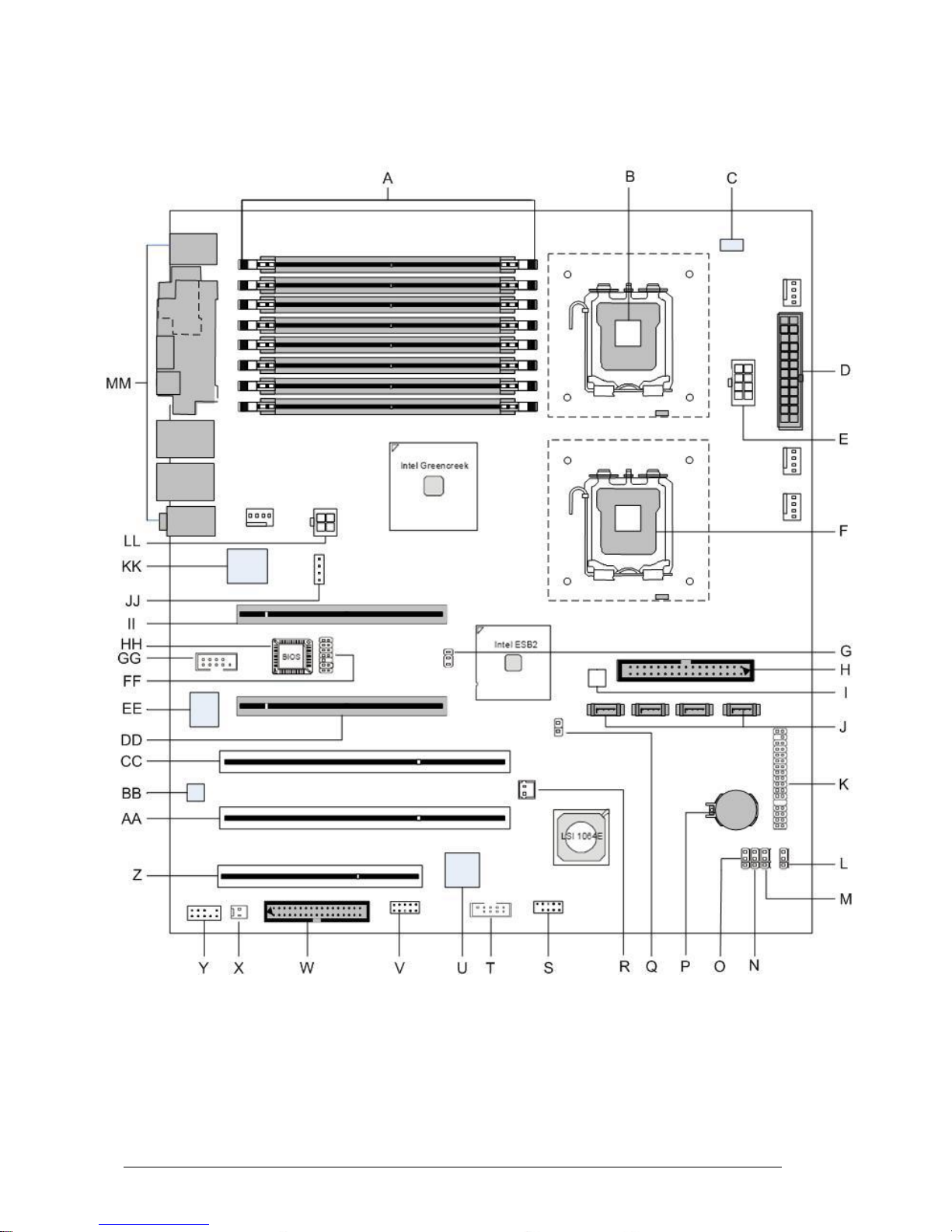
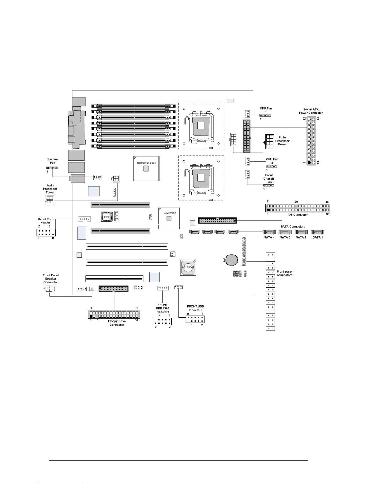
System Board Components
Figure 1: Motherboard Layout & Components
Vig395P Motherboard Manual
11
Page 13
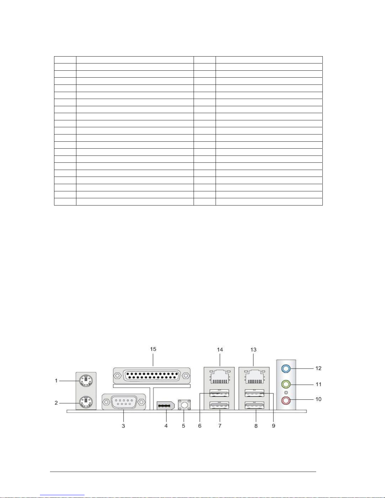
Table 1: Motherboard Connections
Label Description Label Description
A Memory DDR2 FB-DIMM Slots U Single-core graphics processing chip
B LGA771 processor socket (CPU 1) V Reserved connector
C Power LED W Floppy Disk Drive Connector
D Primary 24-pin ATX PWR Connector X Front panel speaker connector
E +12V 8-pin CPU Power Y Front panel audio connector
F LGA771 processor socket (CPU 2) Z 32bit/33MHz PCI slot
G PCI-X frequency select jumper AA 64bit/133MHz PCI-X slot
H IDE1 Optical Drive/ HDD Connector BB Audio chip
I High Performance CPLD CC 64bit/133MHz PCI-X slot
J Intel SATA 0-4 Connectors DD PCI Express x8 on x16
K Front Control Panel Connector EE I/O controller chip
L BIOS Recovery Jumper FF Reserved connector
M Clear CMOS jumper GG Serial port connector
N Reserved jumper HH BIOS ROM chip
O Reserved jumper II PCI-E x16 Slot
P Battery JJ Reserved connector
Q Chassis Intrusion Switch Connector KK LAN controller chip
R Reserved RAID Connector LL +12V 4-pin PCI-Express Power
S Front Panel USB connector MM I/O back panel connectors
T IEEE 1394 Connector
Back Panel Connectors
The Motherboard external IO connectors are attached to a metallic I/O shield. This
shield serves several purposes:
• It protects the sensitive Motherboard from any external EMC interference.
• It stops the computer from interfering with other electrical devices.
• It allows the Motherboard to be easily upgraded in the future without having to
resort to buying a whole new case. Simply change the I/O shield to match the
Motherboard.
The I/O shield provides external access to PS/2 keyboard and mouse connectors as
well as one serial port, one parallel port, four USB ports, one IEEE 1394 port, two LAN
Ports, one NMI button and the audio connectors.
Figure 2: I/O shield
Vig395P Motherboard Manual
12
Page 14
Note: Power to the computer should be turned off before a keyboard or mouse is
connected or disconnected.
Table 2: Back Panel Connectors
Item Description Item Description
1 PS/2* Mouse Port (Green) 8 Back Panel USB 2.0 Port 3
2 PS/2 Keyboard Port (Purple) 9 Back Panel USB 2.0 Port 4
3 Serial Port Connector 10 Microphone (Pink)
4 IEEE 1394N Port 11 Audio Line Out Port (Lime)
5 NMI (Non-Maskable Interrupt) button 12 Audio Line In Port (Light blue)
6 Back Panel USB 2.0 Port 1 13 Gigabit LAN RJ45 2
7 Back Panel USB 2.0 Port 2 14 Gigabit LAN RJ45 1
15 Parallel Port Connector
Note: The back panel audio out connectors are designed to power headphones or
amplified speakers only. Poor audio quality occurs if passive (non-amplified) speakers
are connected to these outputs.
Table 3: Audio 2/4/6 Channel configurations
Port 2 channel 4 channel 6 channel
Audio line In
(Blue)
Line In Line In Bass/Centre
Line Out (Lime
green)
Line out Front Speaker
Out L & R
Front Speaker
Out L & R
Mic in (Pink) Mic In Rear Speaker
Out L & R
Rear Speaker
Out L & R
Vig395P Motherboard Manual
13
Page 15

Feature Summary
The VIG396M Motherboard supports Intel Xeon™ 5300/5100/5000 sequence
(Clovertown/Woodcrest/Dempsey) processors with up to 8 MB Cache integrated in a
LGA 771 Socket package operating at speeds up to 3.73GHz. Single or dual
processors are supported but should be identical in speed and CPU stepping revision.
Table 4: Feature Summary
Form Factor
VIG396M: 30.4 x 33.0 cm
Processor
- Single or dual Xeon 5300/5100/5000 CPU’s
- 1333 MHz, 1066 MHz and 667 MHz
- Integrated 512MB second and 1MB third level cache
- Dual 771-pin LGA Socket
Maximum supported
CPU speeds
CPU Speed FSB L2 Cache
3.73 GHz 1333 MHz 8 MB
Memory
- Eight 240-pin FB-DIMM (Fully Buffered DIMM) sockets.
- Support for up to 32GB of DDR2 667/533MHz FB-DIMM ECC SDRAM
72-bit
Chipset
Intel 5000X chipset, including: the 5000X Memory Control Hub (MCH)
and the Enterprise South Bridge 2 (ESB2)
Video
- PCI-Express connector supporting x8 and x16 lane VGA cards
Audio
- Audio subsystem using the Realtek AC’97 6 channel audio codec.
USB
- Support for USB 2.0 devices
Peripheral Interfaces
- Six USB Ports (4 ports, 1 header)
- Two Serial Port (1 port. 1 header)
- Four Serial ATA ports (Supporting RAID 0,1,10 and 5)
- One IDE Ultra DMA 66/100 bus master interface
- One floppy port interface
- PS/2 keyboard port
- PS/2 mouse port
- Two GLAN (RJ45) ports
- 6-channel Audio Surround Sound
LAN Support
- Intel® (ESB2/Gilgal) 82563EB Dual-Port Gigabit Ethernet Controller
- Supports 10BASE-T, 100BASE-TX, and 1000BASE-T, RJ45 output
- Intel® I/OAT support for fast, scaleable, and reliable networking
BIOS
- 8 Mb Phoenix
®
Flash ROM
- DMI 2.3, PCI 2.2, ACPI 1.0, Plug and Play (PnP), USB Keyboard
support, Hardware BIOS Virus Protection and SMBIOS 2.3
Expansion Capabilities
- 1 x PCI-E x16 and 1x PCI-E x8 slot
- 2 x PCI-X 64-bit 133/100 MHz (3.3V) slot
PC Health Monitoring
- Onboard voltage monitors for CPU cores
- Fan status monitor with firmware control
- CPU/chassis temperature monitors
- Low noise fan speed control
- Platform Environment Control Interface (PECI) ready
- CPU fan auto-off in sleep mode
- Pulse Width Modulation (PWM) fan control
- I2C temperature sensing logic
- Thermal Monitor 2 (TM2) support
- CPU slow-down on temperature overheat
- CPU thermal trip support for processor protection
- Power-up mode control for recovery from AC power loss
- Chassis intrusion detection
Vig395P Motherboard Manual
14
Page 16

Chipset Overview
Built upon the functionality and the capability of the 5000X chipset, the Vig396M
Motherboard provides the performance and feature set required for dual processorbased workstations with configuration options optimized for communications,
presentation, storage, and computation or database applications. The 5000X chipset
supports a single or two Xeon 64-bit dual core processor(s) with front side bus speeds
of up to 1333 MHz. The chipset consists of the 5000X Memory Controller Hub (MCH),
and the Enterprise South Bridge 2 (ESB2).
The 5000X MCH chipset is designed for symmetric multiprocessing across two
independent front side bus interfaces. Each front side bus uses a 64-bit wide, 1333
MHz data bus. The MCH chipset connects up to six Fully Buffered DIMM modules,
providing a total memory of up to 24.0 GB/s. In addition, the 5000X chipset offers a
wide range of RAS features, including memory interface ECC, x4/x8 Single Device
Data Correction, CRC, parity protection, memory mirroring and memory sparing.
The Xeon Dual Core Processor Features
Designed to be used with conjunction of the 5000X chipset, the Xeon dual core
Processor provides a feature set as follows:
The Xeon Dual Core Processors
• L1 Cache Size: Instruction Cache (32KB/16KB), Data Cache (32KB/24KB)
• L2 Cache Size: 4MB (2MB per core)
• Data Bus Transfer Rate: 8.5 GB/s
• Package: FC-LGA6/FC-LGA4, 771 Lands
Vig395P Motherboard Manual
15
Page 17

System Memory
Main Memory
You can install from 512MB to 32GB of memory in the Motherboard DIMM sockets.
The board has eight 240-pin FB (Fully Buffered) DDR2 72bit registered ECC SDRAM
DIMM sockets. The Motherboard supports the following memory features:
• 240-pin DIMMs with gold-plated contacts.
• ECC (72-bit).
• DDR2 533/667 MHz Memory speeds
• 512MB, 1GB, 2GB and 4GB.
Figure 3: Memory Module Description
Memory Population Rules
Each DIMM slot supports up to a maximum size of 4GB. Users can install either single
or double-sided modules depending on their needs.
• The BIOS detects the size and type of installed memory.
Figure 4: DIMM Configuration
Note: To enable successful system boot-up, always insert the memory modules into
DIMM11 first (channel1/1
st
)
Vig395P Motherboard Manual
16
Page 18

Memory Configurations
The Vig396M with Intel 5000X chipset supports the mirroring and sparing technology.
Mirroring mode:
This mode when enabled in the BIOS Branch 2 contains a replicate copy of the data in
Branch 1. The DIMMs must cover the same slot position on both branches. DIMMs that
cover a slot position must be identical with respect to size, speed, and organisation.
DIMMS within a slot position must match each other, but aren’t required to match
adjacent slot positions. Refer to page 113 to enable the memory mirroring functions.
And the default BIOS setting is disabled.
The total memories size will be half of all installed memories.
Single Channel mode:
At configuration time, a DIMM rank is set aside to replace a defective DIMM rank.
When the error rate for a failing DIMM rank reaches a pre-determined threshold, the
memory sparing function will issue an interrupt and initiate a spare copy. At the
completion of the copy, the failing DIMM rank is disabled and the “spared” DIMM rank
will be used in its place. Refer to page 113 to enable the memory sparing functions.
And the default BIOS setting is disabled.
Notes:
1. Each branch contains its own sparing engine and can be enabled or disabled
separately.
2. This Motherboard does not support rank sparing across branches.
3. This Motherboard does not support rank sparing when in mirror mode.
4. The DIMM rank with the largest size will be assigned as spare rank. Data can only
be copied from a smaller sized rank to a larger sized one.
5. A DIMM can contain only one or two ranks. To support sparing function, a DIMM
channel should contain at least two ranks.
6. When sparing function is enabled, the usable memory size will reduce then size of
the spare ranks.
Vig395P Motherboard Manual
17
Page 19
Chapter 2: System Board Options
• The VIG396M Motherboard is capable of accepting Duo Xeon 5300/5100/5000
(Clovertown/Woodcrest/Dempsey) processors. RAM can be upgraded to a
maximum of 32GB using ECC FBD (Fully Buffered) DDR2 667/533 Memory.
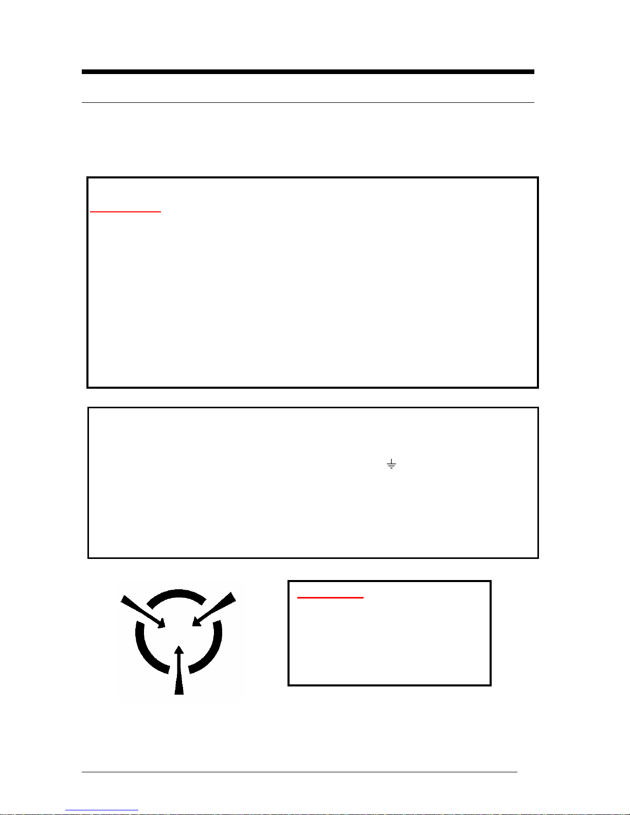
WARNING!
Unplug the system before carrying out the procedures described in this
chapter. Failure to disconnect power before you open the system can result in
personal injury or equipment damage. Hazardous voltage, current, and energy
levels are present in this product. Power switch terminals can have hazardous
Voltages present even when the power switch is off.
The procedures assume familiarity with the general terminology associated with
personal computers and with the safety practices and regulatory compliance
required for using and modifying electronic equipment.
Do not operate the system with the cover removed. Always replace the cover
before turning on the system.
As the colours of the wires in the mains lead of this computer may not correspond with the
coloured markings identifying the terminals in your plug precede as follows:
The wire which is coloured green-and-yellow must be connected to the terminal in the plug
which is marked by the letter E or by the safety Earth symbol or coloured green or green-
and-yellow.
The wire which is coloured blue must be connected to the terminal which is marked with the
letter N or coloured black.
The wire which is coloured brown must be connected to the terminal which is marked with the
letter L or coloured red.
CAUTION!
The Viglen Vig396M Motherboard
and associated components are
sensitive electronic devices. A small
static shock from your body can
cause expensive damage to your
equipment.
Vig395P Motherboard Manual
18
Page 20

Make sure you are earthed and free of static charge before you open the computer
case. If you are unsure about upgrading your computer, return it to Viglen so a qualified
engineer can perform the upgrade.
STEPS TO TAKE TO PREVENT STATIC DISCHARGE:
1. The best way to prevent static discharge is to buy an anti-static strap from your local
electrical shop. While you are wearing the strap and it is earthed, static charge will
be harmlessly bled to ground.
2. Do not remove the component from its anti-static protective packaging until you are
about to install it.
3. Hold boards by the edges – try not to touch components / interface strips etc.
Note: We recommend that you return your computer to the service department for
upgrading. Any work carried out is fully guaranteed. Upgrades should only be carried
out by persons who are familiar with handling IC’s, as incorrect installation will
invalidate the guarantee.
Vig395P Motherboard Manual
19
Page 21
Overview of Jumper Settings
The VIG396M Motherboard contains the latest technology to offer an almost jumper
less configuration. All Xeon CPU’s are automatically detected and the Speed is
automatically set from the information provided by the CPU.
CAUTION!!
1. Never remove jumpers using large pliers as this can damage the pins. The
best way to remove a jumper is to use a small pair of tweezers or fine needlenosed pliers.
2. Do not move the jumper with the power on. Always turn off the power and
unplug the power cord from the computer before changing a jumper, taking
all necessary anti static precautions
System Board Jumper Settings
The following figure shows the jumper locations of the Motherboard. Please refer to the
following tables describing each jumper’s configuration.
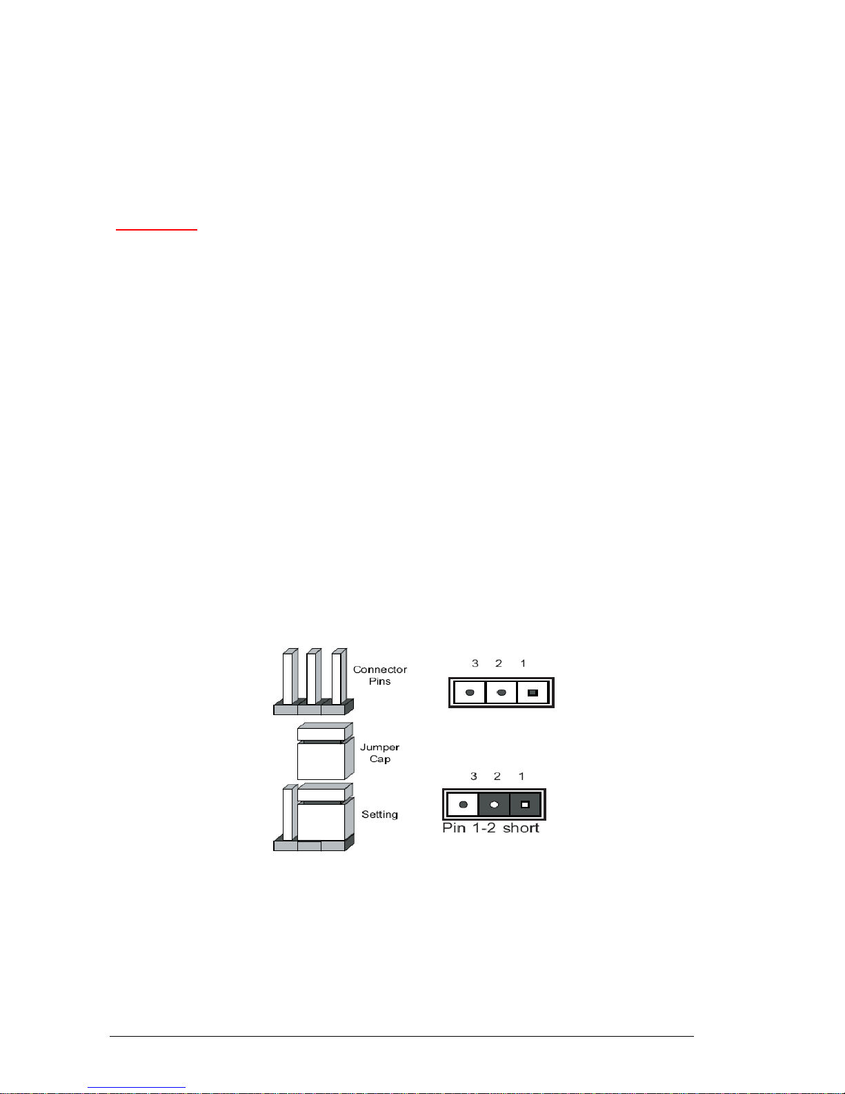
Explanation of Jumpers
To modify the operation of the Motherboard, jumpers can be used to choose between
optional settings. Jumpers create shorts between two pins to change the function of the
connector. Pin 1 is identified with a square solder pad on the printed circuit board.
Note: On two pin jumpers, “Closed” means the jumper is on and “Open” means the
jumper is off the pins.
Figure 5: Explanation of jumpers
Vig395P Motherboard Manual
20
Page 22
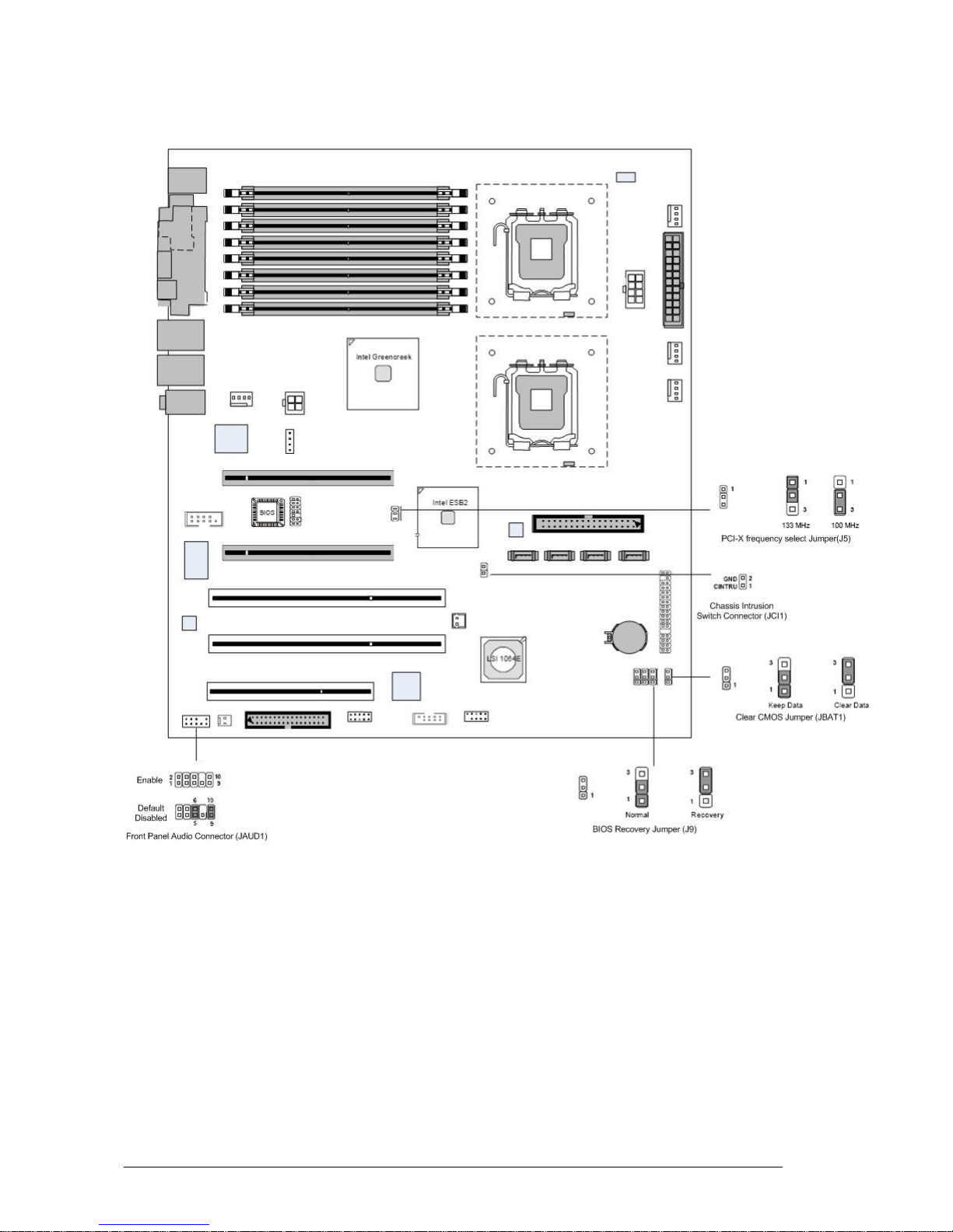
Motherboard Jumper Settings
Figure 6: Motherboard Jumper Settings
Vig395P Motherboard Manual
21
Page 23
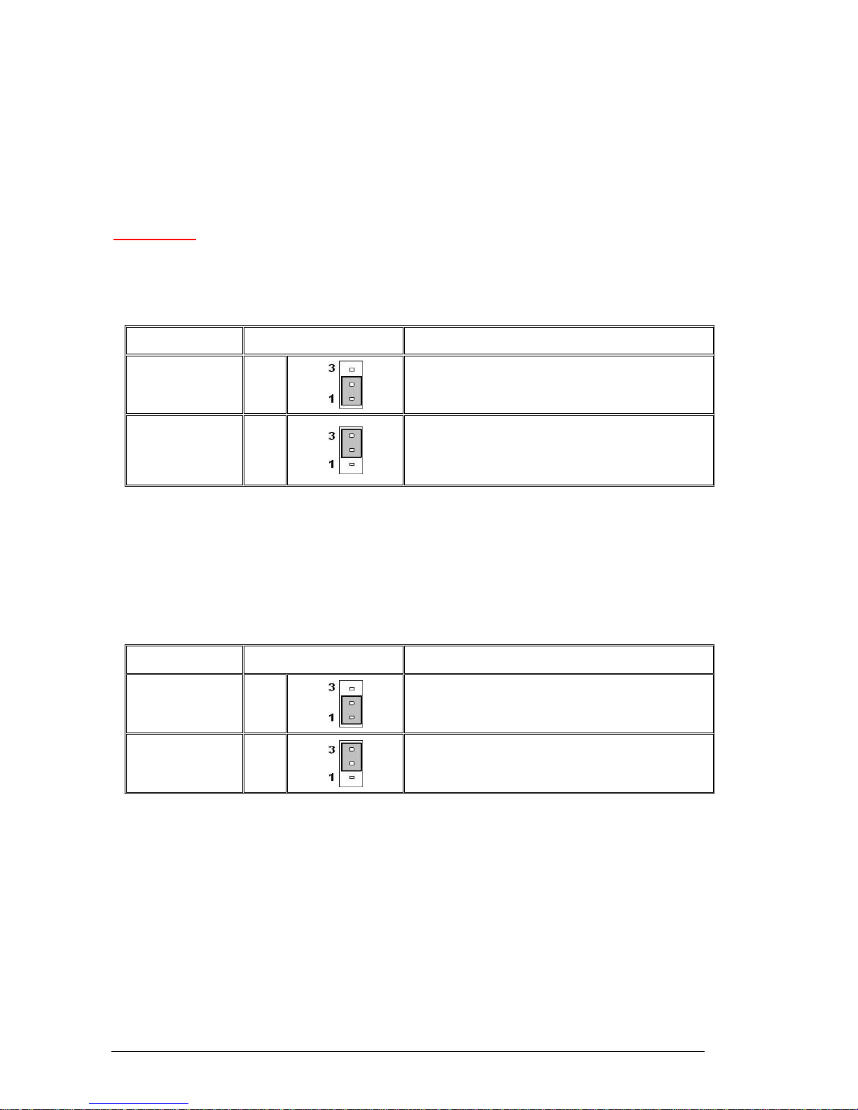
Clear CMOS Jumper (JBAT1)
There is a CMOS RAM onboard that has a power supply from external battery to keep
the data of system configuration. With the CMOS RAM, the system can automatically
boot OS every time it is turned on. If you want to clear the system configuration, set the
JBAT1 (Clear CMOS Jumper) to clear data
CAUTION!!
Avoid clearing the CMOS while the system is on; it will damage the Motherboard
Table 5: Clear CMOS Jumper (JBAT1)
Function/Mode Jumper Setting Configuration
(Default)
Keep Data
1-2
This will keep the system configuration data
saved
Clear Data 2-3
This will clear the system configuration data
saved
BIOS Recovery Jumper (J9)
Users can short connect pin#1-3 to recover the system BIOS with a Recovery Floppy
disk. When the system is done with the job, the buzzer will beep to remind the user to
set the jumper to its normal state (pin#1-2 short connected).
Table 6: BIOS Recovery Jumper (J9)
Function/Mode Jumper Setting Configuration
(Default)
Normal
1-2
This keeps the system in its normal state
Recovery 2-3
This will force the system to carry out a BIOS
Recovery using a Recovery floppy disk.
Vig395P Motherboard Manual
22
Page 24
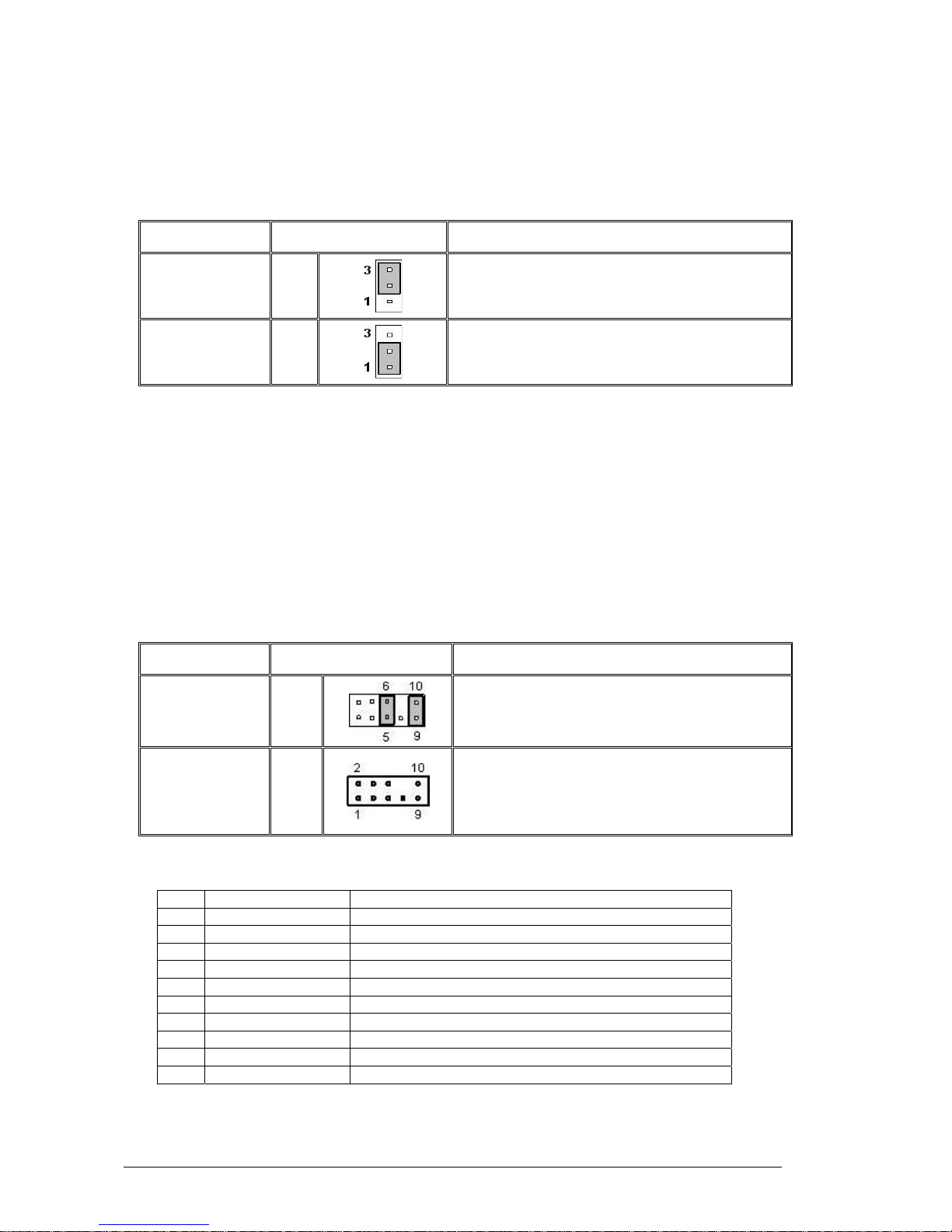
PCI-X frequency select Jumper (J5)
This Jumper is used to select the frequency of PCI-X slots.
Table 7: PCI-X frequency select jumper (J5)
Function/Mode Jumper Setting Configuration
(Default)
133MHz
1-2
This sets the PCI-X frequency to 133MHz
100MHz 2-3
This sets the PCI-X frequency to 100MHz
Front Panel Audio Connector (JAUD1)
When front panel headphones are plugged in, the back panel audio output is disabled.
This is done through the FP Audio header (JAUD1). If the front panel interface card is
not connected to the front panel audio header, jumpers should be installed on the
header (JAUD1) pin pairs: 5-6, and 9-10. If these jumpers are not installed, the back
panel line out connector will be disabled and microphone input Pin 1 will be left floating,
which can lead to excessive back panel microphone noise and cross talk. The table
below describes the jumper settings.
Table 8: Front Panel Audio Jumpers (Front panel audio)
Function/Mode Jumper Setting Configuration
(Default)
5-6
and
9-10
Allows audio to pass to rear I/O with no front
audio cable. The audio line signals are routed
back to the line connector.
Front panel
audio
Open
Jumpers removed for front panel audio cable.
Audio line out and mic in signals are available
for front panel audio connectors on this
connector when no jumpers are installed.
Table 9: Front panel Audio Connector
PIN SIGNAL DESCRIPTION
1 AUD_MIC Front panel microphone input signal
2 AUD_GND Ground used by analog audio circuits
3 AUD_MIC_BIAS Microphone power
4 AUD_VCC Filtered +5V used by analog audio circuits
5 AUD_FPOUT_R Right channel audio signal to front panel
6 AUD_RET_R Right channel audio signal return from front panel
7 HP_ON Reserved for future use to control headphone amplifier
8 KEY No pin
9 AUD_FPOUT_L Left Channel audio signal to front panel
10 AUD_RET_L Left channel audio signal return from front panel
Vig395P Motherboard Manual
23
Page 25
Motherboard Connectors
There are connectors on the Motherboard for FAN, IDE, Power supply, CD audio,
Floppy, IDE, & Front Panel Connectors. The location and/or details of these
connections are shown below.
Figure 7: Motherboard Connections
Vig395P Motherboard Manual
24
Page 26
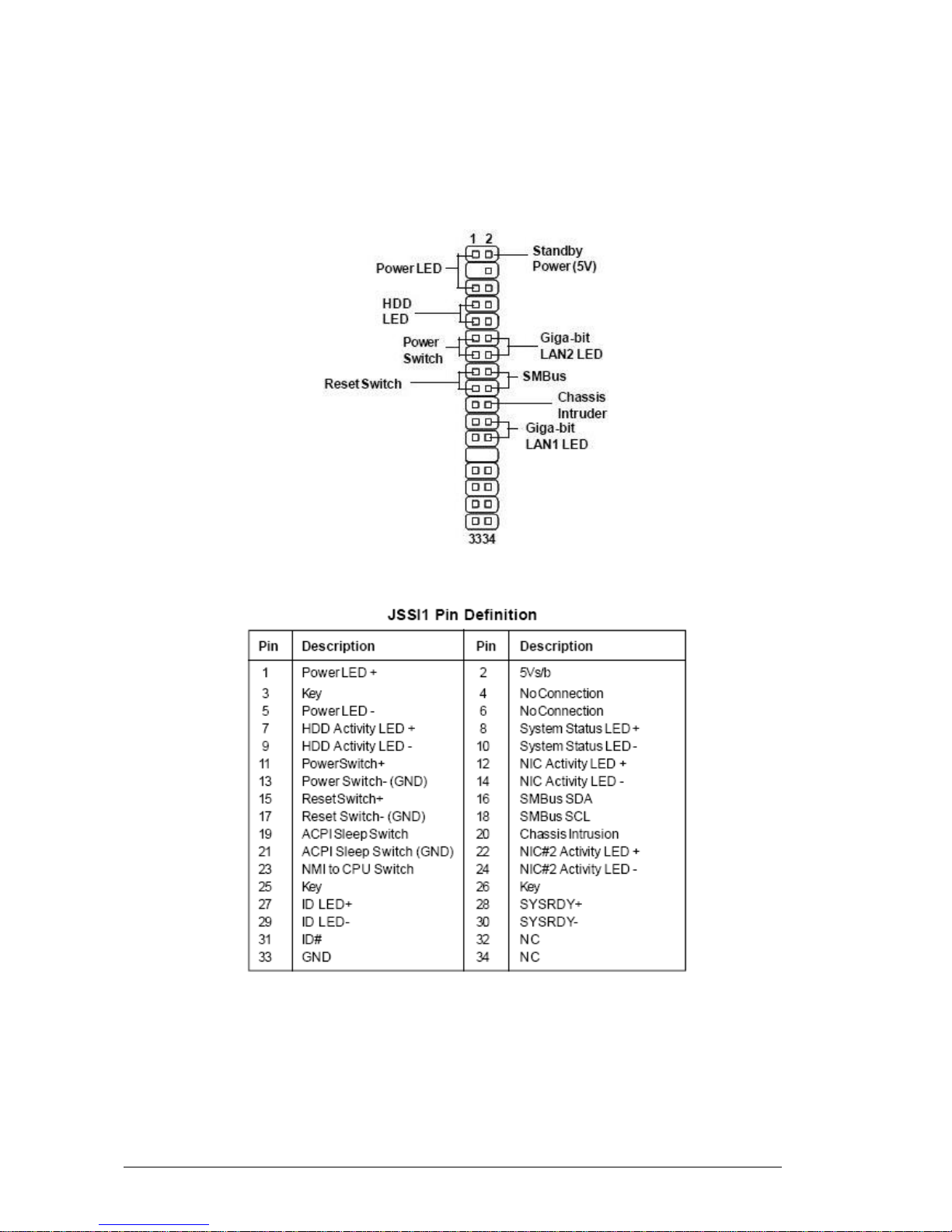
Front panel connections (JSSI1)
The following are all connectors situated along the right edge of the Motherboard.
They are often connected to buttons and LED’s situated on the front panel.
Figure 8: Front panel connections
A- Power LED
This 2-pin connector is for the system power LED. Connect the chassis power LED
cable to this connector. The system power LED lights up when you turn on the system
power, and blinks when the system is in sleep mode.
Vig395P Motherboard Manual
25
Page 27

B- HDD (Hard disk drive) LED
This 2-pin connector is for the HDD activity LED. Connect the HDD Activity LED cable
to this connector. The IDE LED lights up or flashes when data is read from or written to
the HDD.
C- Power Switch
This connector is for the system power button. Pressing the power button turns the
system on or puts the system in sleep or soft-off mode depending on the BIOS settings.
Pressing the power switch for more than four seconds while the system is ON turns the
system OFF.
D- Reset Switch
This 2-pin connector is for the chassis-mounted reset button for system reboot without
turning off the system power.
E- SMBus Connector
This 2-pin connector is used for communication with low-bandwidth devices on the
Motherboard. A device can provide manufacturer information, indicate its model/part
number, save its state for a suspend event, report different types of errors, accept
control parameters, and return status.
F- Giga-bit LAN1/LAN2 LED Indicators
These connectors are for the network activity LED. Connect the NIC LED cables to this
connector. Anytime a network cable is connected to a NIC the LED will light up.
G- Chassis Intruder
This connector connects to a 2-pin chassis switch. If the chassis is opened, the switch
will be short. The system will record this status and show a warning message on the
screen. To clear the warning, you must enter the BIOS utility and clear the record.
Vig395P Motherboard Manual
26
Page 28
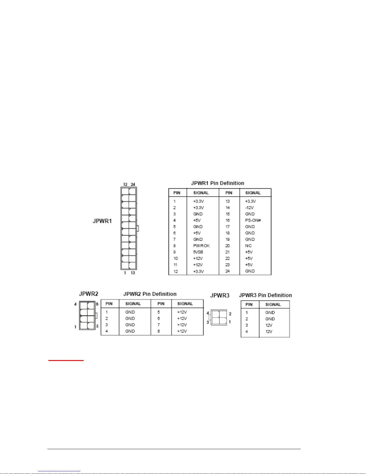
Power Connectors
SSI 24-Pin System Power Connector (JPWR1)
This connector allows you to connect to an SSI power supply. To connect to the SSI
power supply, make sure the plug of the power supply is inserted in the proper
orientation and the pins are aligned. Then push down the power supply firmly into the
connector.
SSI 8-pin CPU Power Connector (JPWR2)
This connector provides 12V power output to the CPU’s.
SSI 4-Pin VGA Power Connector (JPWR3)
Make sure to connect this connector with a 12V power supply to ensure stable
operation of the graphics card.
Figure 9: Power Connectors
CAUTION!!
Do not forget to connect the 24+8+4-pin power plugs; otherwise, the system will
not boot up.
Vig395P Motherboard Manual
27
Page 29
Connectors
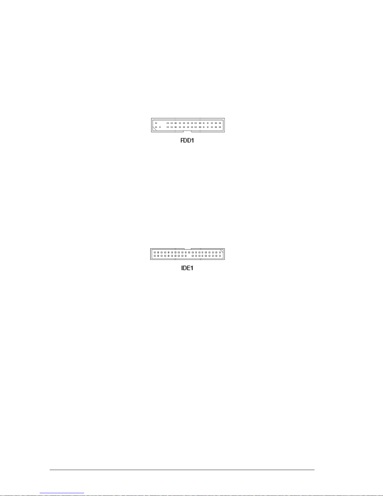
Floppy Disk Drive Connector (FDD1)
This connector is for the provided floppy disk drive (FDD) signal cable. Insert one end
of the cable to this connector, and then connect the other end to the signal connector at
the back of the floppy disk drive. This standard FDD connector supports 360K, 720K,
1.2M, 1.44M and 2.88M floppy disk types.
Figure 10: Floppy disk drive connector
IDE Connector (IDE1)
The Motherboard has a 32-bit Enhanced PCI IDE and Ultra DMA 66/100 controller that
provides PIO mode 0~4, Bus Master, and Ultra DMA 66/100 function. You can connect
hard disk drives, CD-ROM and other IDE devices.
The Ultra ATA100 interface boosts data transfer rates between the computer and the
hard drive up to 100 megabytes (MB) per second. The new interface is backward
compatible with the existing Ultra ATA interface.
Figure 11: IDE Connector
Note: If you install two hard disks on cable, you must configure the second drive to
Slave mode by setting its jumper. Refer to the hard disk documentation supplied by
hard disk vendors for jumper setting instructions.
Vig395P Motherboard Manual
28
Page 30
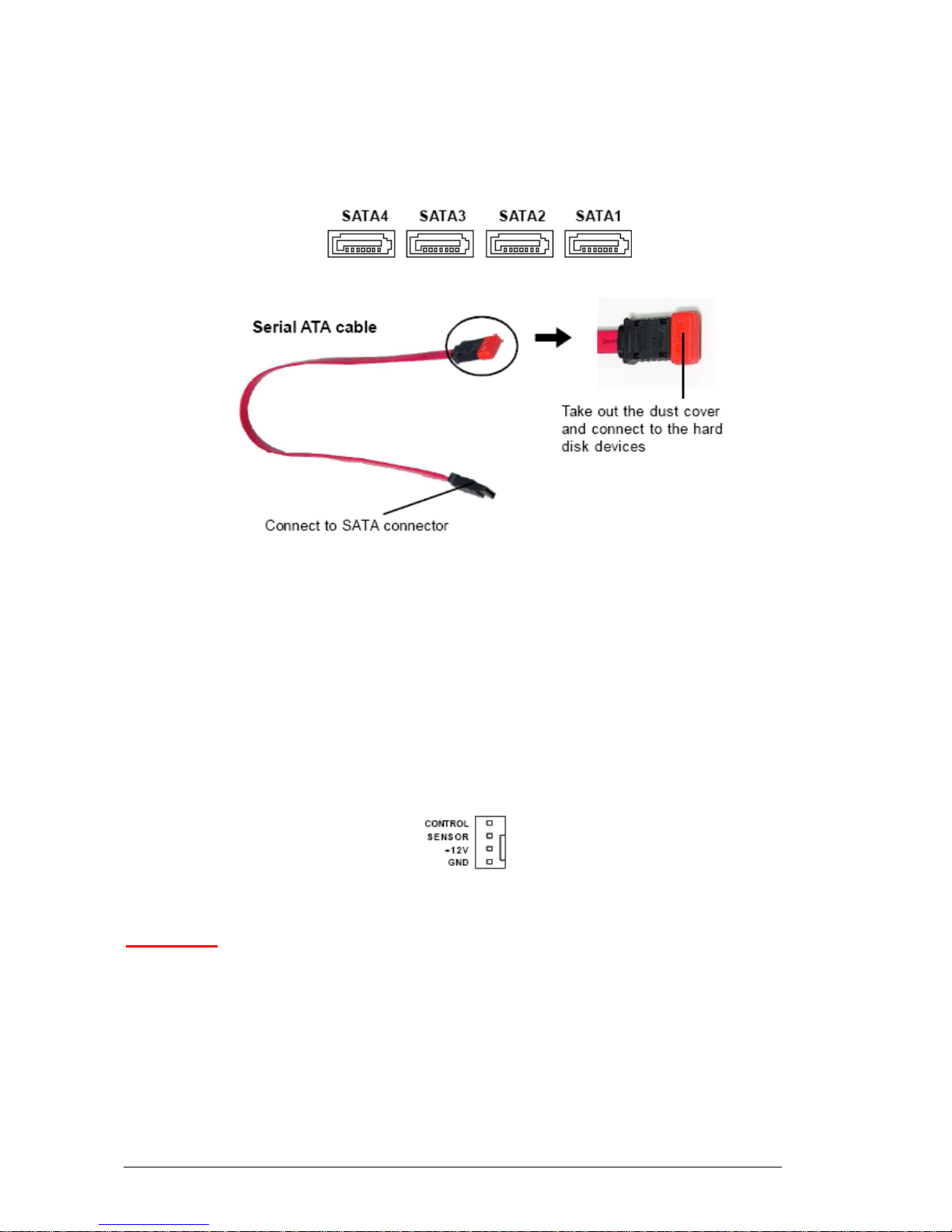
Serial ATA Connectors: SATA1~SATA4
SATA1~SATA4 are high-speed SATAII interface ports and support data rates of
300MB/s. Each SATAII connector can connect to 1 hard disk device
Figure 12: SATA Connector
Note: Please do not fold the Serial ATA cable into 90-degree angle. Otherwise, data
loss may occur during transmission
Fan Power Connectors (CPUFAN1~2/SYSFAN1~2)
The fan power connectors support system cooling fan with +12V. When connecting the
wire to the connectors, always take note that the red wire is the positive and should be
connected to the +12V, the black wire is Grounded and should be connected to GND. If
the Motherboard has a system Hardware Monitor chipset on-board, you must use
specially designed fan with speed sensor to take advantage of the CPU fan control.
Figure 13: Fan Power Connectors
CAUTION!!
Do not forget to connect the fan cables to the fan connectors. Insufficient air
flow inside the system may damage the Motherboard components. These are not
jumpers!! Do not place jumper caps on the fan connectors!!
Vig395P Motherboard Manual
29
Page 31

Serial Port Connector (COM2)
The Motherboard provides one 9-pin header as serial port. The port is a 16550A high
speed communication port that sends/receives 16 bytes FIFOs. You can attach a serial
mouse or other serial devises directly to it.
Figure 14: Serial Port Connector
Chassis Intrusion Switch Connector (JCI1)
This connector connects to a 2-pin chassis switch. If the chassis is opened, the switch
will be short. The system will record this status and show a warning message on the
screen. To clear the warning, you must enter the BIOS utility and clear the record.
Figure 15: Chassis Intrusion Switch Connector
Front Panel Speaker Connector (JSPK1)
This connector connects to a 2-pin speaker on the front panel.
Figure 16: Front Panel Speaker Connector
Vig395P Motherboard Manual
30
Page 32

IEEE 1394 Connector (J1394CON1)
The Motherboard provides an IEEE1394 pin header that allows you to connect IEEE
1394 ports via an external IEEE1394 bracket (optional).
Figure 17: IEEE 1394 Connector
Front USB Connectors (JUSB1)
The Motherboard provides one USB 2.0 pin header that is compliant with Intel I/O
Connectivity Design Guide. USB 2.0 technology increases data transfer rate up to a
maximum throughput of 480Mbphs, which is 40 times faster than USB 1.1, and is ideal
for connecting high-speed USB interface peripherals such as USB HDD, digital
cameras, MP3 players, printers, modems and others alike.
Figure 18: Front USB Connector
Note: The pins of VCC and GND must be connected correctly to avoid possible
damage
Vig395P Motherboard Manual
31
Page 33

Upgrading the Central Processing Unit (CPU)
The Motherboard comes with a surface mount LGA771 socket designed for the Intel®
Xeon Dual Core processor
CAUTION!!
When handling the processor package, avoid placing direct pressure on the label
area of the fan.
Notes:
1. Always connect the power cord last and always remove it before adding, removing
or changing any hardware components. Make sure that you install the processor
into the CPU socket before you install the CPU heatsink.
2. Make sure you install the Motherboard into the chassis before you install the CPU
heatsink and fan.
All Intel® Processors together with Level 2 cache chips are housed in a protective
package.
The design of the VIG396M computer makes it a simple job to replace or upgrade the
processor. To do so please refer to the follow instructions below:
Vig395P Motherboard Manual
32
Page 34

Un-install the Heatsink
1. Remove the lid from the system by un-screwing the two screws at the rear of the
case
CPU heatsink (Top View) CPU heatsink (Bottom View)
Figure 19: Xeon Active CPU heatsink
2. Unscrew and remove the heatsink screws from the Motherboard in the sequence as
shown in the picture below.
Figure 20: Heatsink screws
3. Gently wriggle the heatsink to loosen it from the CPU. (Do not use excessive force
when wriggling the heatsink!!).
4. Once the heatsink is loosened, remove the heatsink from the CPU socket.
5. Clean the surface of the CPU and the heatsink to get rid of the old thermal grease.
Reapply the proper amount of thermal grease on the surface before you re-install
the CPU and the heatsink.
Vig395P Motherboard Manual
33
Page 35

Installing the CPU:
The Motherboard supports Intel 5300/5100/5000 sequence in a LGA771 socket. When
you are installing the CPU, make sure the CPU has a heat sink and a cooling fan
attached on the top to prevent overheating.
Note:
1. Overheating will seriously damage the CPU and system. Always make sure the
cooling fan can work properly to protect the CPU from overheating.
2. Make sure that you apply an even layer of heat sink paste (or thermal tape)
between the CPU and the heat sink to enhance heat dissipation.
3. While replacing the CPU, always turn off the ATX power supply or unplug the power
supply’s power cord from the grounded outlet first to ensure the safety of CPU
Figure 21: LGA 771 CPU
1. Flip over the Motherboard and locate the position of the CPU sockets
2. Install the backplates to the back of the CPU sockets with holes aligned.
Figure 22: Installing CPU Heatsink Backplate
Vig395P Motherboard Manual
34
Page 36

3. Locate the CPU socket and raise the load lever up to its full extent.
Figure 23: CPU Socket and Load Lever
3. Open the load plate.
Figure 24: Load Lever
4. After confirming the CPU direction (indicated below with red circles) for correct
mating, put down the CPU on the socket housing frame. Be sure to grasp on the
edge of the CPU base. Note that the alignment keys are matched.
5. Visually inspect if the CPU is seated well into the socket. If not, take out the CPU
with pure vertical motion and reinstall.
6. Cover the load plate onto the package
7. Press down the load lever lightly onto the load plate and then secure the lever with
the hook under the retention tab.
Figure 25: CPU alignment and securing CPU
Vig395P Motherboard Manual
35
Page 37

Installing Heatsink
1. Do not apply any thermal grease to the heatsink or the CPU die; if it has already
been applied. If Heatsink thermal paste is not already applied to heatsinks this must
be done now.
2. Place the heatsink on top of the CPU so that the four mounting holes are aligned
with those on the retention mechanism.
3. Screw in two diagonal screws (i.e. the #1 and the #2 screws) until just snug (Do not
fully tighten the screws to avoid possible damage to the CPU.)
Figure 26: Heatsink diagonal screw locations
4. Finish the installation by fully tightening all four screws.
5. Repeat the steps for the second heatsink if required.
Vig395P Motherboard Manual
36
Page 38

Upgrading System Memory
You can install from 512MB to 32GB of memory in the Motherboard DIMM sockets.
The board has eight 240-pin FB (Fully Buffered) DDR2 72bit registered ECC SDRAM
DIMM sockets. The Motherboard supports the following memory features:
• 240-pin DIMMs with gold-plated contacts.
• ECC (72-bit).
• DDR2 533/667 MHz Memory speeds
• 512MB, 1GB, 2GB and 4GB.
Figure 27: Memory Module Description
Memory Population Rules
Each DIMM slot supports up to a maximum size of 4GB. Users can install either single
or double-sided modules depending on their needs.
• The BIOS detects the size and type of installed memory.
Figure 28: DIMM Configuration
Note: To enable successful system boot-up, always insert the memory modules into
DIMM11 first (channel1/1
st
)
Vig395P Motherboard Manual
37
Page 39

Memory Configurations
The Vig396M with Intel 5000X chipset supports the mirroring and sparing technology.
Mirroring mode:
This mode when enabled in the BIOS Branch 2 contains a replicate copy of the data in
Branch 1. The DIMMs must cover the same slot position on both branches. DIMMs that
cover a slot position must be identical with respect to size, speed, and organisation.
DIMMS within a slot position must match each other, but aren’t required to match
adjacent slot positions. Refer to page 113 to enable the memory mirroring functions.
And the default BIOS setting is disabled.
The total memories size will be half of all installed memories.
Single Channel mode:
At configuration time, a DIMM rank is set aside to replace a defective DIMM rank.
When the error rate for a failing DIMM rank reaches a pre-determined threshold, the
memory sparing function will issue an interrupt and initiate a spare copy. At the
completion of the copy, the failing DIMM rank is disabled and the “spared” DIMM rank
will be used in its place. Refer to page 113 to enable the memory sparing functions.
And the default BIOS setting is disabled.
Notes:
7. Each branch contains its own sparing engine and can be enabled or disabled
separately.
8. This Motherboard does not support rank sparing across branches.
9. This Motherboard does not support rank sparing when in mirror mode.
10. The DIMM rank with the largest size will be assigned as spare rank. Data can only
be copied from a smaller sized rank to a larger sized one.
11. A DIMM can contain only one or two ranks. To support sparing function, a DIMM
channel should contain at least two ranks.
12. When sparing function is enabled, the usable memory size will reduce then size of
the spare ranks.
Vig395P Motherboard Manual
38
Page 40

Installing Memory Modules
1. The memory module has only one notch on the center and will only fit in the right
orientation.
2. Insert the memory module vertically into the DIMM slot. Then push it in until the
golden finger on the memory module is deeply inserted in the DIMM slot.
Note: You can barely see the golden finger if the memory module is properly inserted
in the DIMM slot
3. The plastic clip at each side of the DIMM slot will automatically close.
Figure 29: Installing Memory Module
Note: Make sure that you install memory modules of the same type and density on
DDRII DIMMs.
Vig395P Motherboard Manual
39
Page 41

Removing Memory Modules
1. Simultaneously press the retaining clips outward to unlock the DIMM
Note: Support the DIMM lightly with your fingers when pressing the retaining clips. The
DIMM might get damaged when it flips out with extra force.
2. Remove the DIMM from the socket
Figure 30: Removing Memory Module
Vig395P Motherboard Manual
40
Page 42

Installing an expansion card
To install an expansion card:
1. Before installing the expansion card, read the documentation that came with it and
make the necessary hardware settings for the card.
2. Remove the lid from the system by un-screwing the two screws at the rear of the
case
2. Remove the bracket opposite the slot that you intend to use. Keep the screw for
later use.
3. Align the card connector with the slot and press firmly until the card is completely
seated on the slot.
4. Secure the card to the chassis with the screw you removed earlier.
5. Replace the system lid.
Configuring an expansion card
After installing the expansion card, configure the card by adjusting the software
settings.
1. Turn on the system and change the necessary BIOS settings, if any.
2. Install the software drivers for the expansion card.
PCI Slots
There are two 64-bit PCI slots on this Motherboard. The slots support PCI cards such
as a LAN card, SCSI card, USB card, and other cards that comply with PCI
specifications.
Figure 31: Installing a PCI card
Vig395P Motherboard Manual
41
Page 43

PCI Express x16 Slot
This Motherboard supports PCI Express x16 graphic cards that comply with the PCI
Express specifications.
Figure 44 shows a graphics card installed on the PCI Express x16 slot.
Figure 32: Install a PCI Express x16 card
Vig395P Motherboard Manual
42
Page 44

Replacing the Clock/CMOS RAM Battery
A lithium battery is installed in a socket on the system board.
The battery has an estimated life expectancy of seven years. When the battery starts
to weaken, it loses voltage; when the voltage drops below a certain level, the system
settings stored in CMOS RAM (for example, the date and time) may be wrong.
If the battery fails, you will need to replace it with a CR2032 battery or an equivalent. As
long as local ordinance permits, you may dispose of individual batteries as normal
rubbish. Do not expose batteries to excessive heat or any naked flame. Keep all
batteries away from children.
CAUTION!!
Danger of explosion if the battery is incorrectly replaced. Replace only with the
same or equivalent type recommended by Viglen. Discard used batteries
according to manufacturer’s instructions.
The battery is listed as board component ‘K’ on the diagram on Figure 1.
To replace the battery, carry out the following:
1. Observe the precautions in “Before You Begin.”
2. Turn off all peripheral devices connected to the system.
3. Turn off the system.
4. Remove any components that are blocking access to the battery.
5. Figure 1 shows the battery location. Gently pry the battery free from its socket,
taking care to note the "+" and "-" orientation of the battery (Figure 45).
6. Install the new battery in the socket.
1
+
+
2
Figure 33: Removing the Battery
Vig395P Motherboard Manual
43
Page 45

Chapter 3: Solving Problems
The first part of this chapter helps you identify and solve problems that might occur
when the system is in use. The second part lists error code messages that might be
displayed.
Please remember that if you cannot solve the problem by yourself then you should
contact Viglen’s Technical Support team for further assistance.
Viglen Technical Support can be reached in the following ways:
Telephone: 01727 201 850
Fax: 01727 201 858
Email: techsupport@viglen.co.uk
You can also look for support information on our web site:
http://www.viglen.co.uk
Device drivers and various useful utilities can be downloaded from our ftp site:
ftp://ftp.viglen.co.uk
Resetting the System
Before checking your system for hardware problems, it is always a good idea to try
resetting your computer and see if a re-boot can solve the problem. Most software
related problems can be solved simply by re-booting your PC.
Table 10: Resetting the System
To do the following Press
Soft boot: Clear the system memory and
reload the operating system (also called
warm reset).
<Ctrl + Alt + Del>
Cold boot: Clear the system memory, halt
power to all peripherals, restart POST, and
reload the operating system.
Power off/on or reset button (at front
of the system)
Vig395P Motherboard Manual
44
Page 46

Troubleshooting Procedures
This section provides a step-by-step troubleshooting procedure to identify a problem
and locate its source.
CAUTION!!
1. Turn off the system and any peripheral devices before you disconnect any
peripheral cables from the system. Otherwise, you can permanently damage
the system or the peripheral devices.
2. Make sure the system is plugged into a properly grounded power outlet.
3. Make sure your keyboard and video display are correctly connected to the
system. Turn on the video display, and turn up its brightness and contrast
controls to at least two-thirds of the maximum (refer to the documentation
supplied with the video display).
4. If the operating system normally loads from the hard disk drive, make sure
there is no diskette in the diskette drive. If the operating system normally
loads from a diskette, insert the operating system diskette into the drive.
5. Turn on the system. If the power indicator does not light, but the system
seems to be operating normally, the indicator is probably defective. Monitor
the power-on self test (POST) execution. Each time you turn on the system,
the POST checks the system board, memory, keyboard, and certain peripheral
devices.
Note: If the POST does not detect any errors, the system beeps once and boots up.
Errors that do not prevent the boot process (non-fatal errors) display a message that
looks similar to the following:
Error Message Line 1
Error Message Line 2
Press <F1> for Set-up, <F2> to Boot
You can note the error and press <F2> to resume the boot- up process, or
<F1> to enter Set-up.
Errors that prevent the boot process from continuing (fatal errors), are communicated
by a series of audible beeps. If this type of error occurs, refer to the error codes and
messages listed at the end of this chapter.
6. Confirm that the operating system has loaded.
Vig395P Motherboard Manual
45
Page 47

Problems Operating Add-in Boards
Problems related to add-in boards are usually related to improper board installation or
interrupt and address conflicts. Go through the checklist below to see if you can
correct the problem. If the problem persists after you have checked and corrected all of
these items, contact the board vendor's customer service representative.
Did you install the add-in board according to the manufacturer’s instructions?
Check the documentation that came with the board. Are all cables installed properly?
The following items are suggestions for troubleshooting problems related to PCI/ISA
legacy (non-Plug and Play) add-in boards.
• If the PCI/ISA board uses an interrupt, run Set-up and set the interrupt that is
being used by the PCI/ISA board to Used by PCI/ISA Card. Please refer to the
BIOS manual for details of how to do this.
• If the PCI/ISA legacy board uses memory space between 80000H - 9FFFFH,
run Set-up and set conventional memory to 256 K.
• If the PCI/ISA legacy board uses shared memory between C8000H - DFFFH,
run Set-up and enable shared memory for the appropriate memory space.
Vig395P Motherboard Manual
46
Page 48

Problems and Suggestions
Table 11: Problems and Suggestions
What happens What to do
Application software
problems
Try resetting the system.
Make sure all cables are installed correctly.
Verify that the system board jumpers are set properly.
Verify that your system hardware configuration is set correctly. In
Setup, check the values against the system settings you recorded
previously. If an error is evident (wrong type of drive specified, for
example), make the change in Setup and reboot the system. Record
your change.
Make sure the software is properly configured for the system. Refer to
the software documentation for information.
Try a different copy of the software to see if the problem is with the
copy you are using.
If other software runs correctly on the system, contact the vendor of
the software that fails.
If you check all of the above with no success, try clearing CMOS
RAM and reconfiguring the system. Make sure you have your list of
system settings available to re-enter, because clearing CMOS RAM
sets the options to their default values.
Characters onscreen are distorted
or incorrect
Make sure the brightness and contrast controls are properly adjusted
on the monitor.
Make sure the video signal cable and power cables are properly
installed.
Make sure your monitor is compatible with the video mode you have
selected.
Characters do not
appear on screen
Make sure the video display is plugged in and turned on.
Check that the brightness and contrast controls are properly adjusted.
Check that the video signal cable is properly installed.
Make sure a video board is installed, enabled, and the jumpers are
positioned correctly.
Reboot the system.
CMOS RAM settings
are wrong
If system settings stored in CMOS RAM change for no apparent
reason (for example, the time of day develops an error), the backup
battery may no longer have enough power to maintain the settings.
Replace the battery.
Diskette drive light
does not go on when
drive is in use or is
tested by POST
Make sure the power and signal cables for the drive are properly
installed.
Check that the drive is properly configured and enabled in Setup.
Vig395P Motherboard Manual
47
Page 49

Table 12: Problems and Suggestions (Continued)
What happens What to do
Hard drive light does
not go on when drive
is in use or is tested
by POST
Make sure the power and signal cables for the drive are properly
installed.
Make sure the front panel connector is securely attached to the
system board headers.
Check that the drive is properly configured and enabled in Setup.
Check the drive manufacturer's manual for proper configuration for
remote hard disk drive activity.
Power-on light does
not go on
If the system is operating normally, check the connector between the
system board and the front panel. If OK, the light may be defective.
Prompt doesn't
appear after system
boots
It’s probably switched off.
A serious fault may have occurred consult your dealer service
department / Technical Support.
Setup, can't enter
If you can't enter Setup to make changes, check the switch that
disables entry into Setup (Chapter 2). If the switch is set to allow
entry into Setup, you might need to clear CMOS RAM to the default
values and reconfigure the system in Setup.
System halts before
completing POST
This indicates a fatal system error that requires immediate service
attention. Note the screen display and write down any beep code
emitted. Provide this information to your dealer service department /
Technical Support.
Vig395P Motherboard Manual
48
Page 50

Error and Information Messages
BIOS POST Messages
During the Power-On Self-Test (POST), the BIOS will check for problems. If a problem
is found, the BIOS will activate an alarm or display a message. The following is a list of
such BIOS messages.
Failure Fixed Disk
Fixed disk is not working or not configured properly. Check to see if fixed disk is
attached properly. Run Setup. Find out if the fixed-disk type is correctly identified.
Stuck key
Stuck key on keyboard.
Keyboard error
Keyboard not working.
Keyboard Controller Failed
Keyboard controller failed test. May require replacing keyboard controller.
Keyboard locked - Unlock key switch
Unlock the system to proceed.
Monitor type does not match CMOS - Run SETUP
Monitor type not correctly identified in Setup
Shadow Ram Failed at offset: nnnn
Shadow RAM failed at offset nnnn of the 64k block at which the error was detected.
System RAM Failed at offset: nnnn
System RAM failed at offset nnnn of in the 64k block at which the error was detected.
Extended RAM Failed at offset: nnnn
Extended memory not working or not configured properly at offset nnnn.
System battery is dead - Replace and run SETUP
The CMOS clock battery indicator shows the battery is dead. Replace the battery and
run Setup to reconfigure the system.
System CMOS checksum bad - Default configuration used
System CMOS has been corrupted or modified incorrectly, perhaps by an application
program that changes data stored in CMOS. The BIOS installed Default Setup Values.
If you do not want these values, enter Setup and enter your own values. If the error
persists, check the system battery or contact your dealer.
System timer error
The timer test failed. Requires repair of system board.
Vig395P Motherboard Manual
49
Page 51

Real time clock error
Real-Time Clock fails BIOS hardware test. May require board repair.
Check date and time settings
BIOS found date or time out of range and reset the Real-Time Clock. May require
setting legal date (1991-2099).
Previous boot incomplete - Default configuration used
Previous POST did not complete successfully. POST loads default values and offers to
run Setup. If the failure was caused by incorrect values and they are not corrected, the
next boot will likely fail. On systems with control of wait states, improper Setup settings
can also terminate POST and cause this error on the next boot. Run Setup and verify
that the wait state configuration is correct. This error is cleared the next time the system
is booted.
Memory Size found by POST differed from CMOS
Memory size found by POST differed from CMOS.
Diskette drive A error
Drive A: is present but fails the BIOS POST diskette tests. Check to see that the drive
is defined with the proper diskette type in Setup and that the diskette drive is attached
correctly.
Incorrect Drive A type - run SETUP
Type of floppy drive A: not correctly identified in Setup.
System cache error - Cache disabled
RAM cache failed and BIOS disabled the cache. On older boards, check the cache
jumpers. You may have to replace the cache. See your dealer. A disabled cache slows
system performance considerably.
CPU ID:
CPU socket number for Multi-Processor error.
EISA CMOS not writeable
ServerBIOS2 test error: Cannot write to EISA CMOS.
DMA Test Failed
ServerBIOS2 test error: Cannot write to extended DMA (Direct Memory Access)
registers.
Software NMI Failed
ServerBIOS2 test error: Cannot generate software NMI (Non-Maskable Interrupt).
Fail-Safe Timer NMI Failed
Server BIOS2 test error: Fail-Safe Timer takes too long.
Device Address Conflict
Address conflict for specified device.
Vig395P Motherboard Manual
50
Page 52

Allocation Error for: device
Run ISA or EISA Configuration Utility to resolve resource conflict for the specified
device.
CD ROM Drive
CD ROM Drive identified.
Entering SETUP...
Starting Setup program
Failing Bits: nnnn
The hex number nnnn is a map of the bits at the RAM address which failed the
memory test. Each 1 (one) in the map indicates a failed bit. See errors 230, 231, or 232
above for offset address of the failure in System, Extended, or Shadow memory.
Fixed Disk n
Fixed disk n (0-3) identified.
Invalid System Configuration Data
Problem with NVRAM (CMOS) data.
I/O device IRQ conflict
I/O device IRQ conflict error.
PS/2 Mouse Boot Summary Screen:
PS/2 Mouse installed.
nnnn kB Extended RAM Passed
Where nnnn is the amount of RAM in kilobytes successfully tested.
nnnn Cache SRAM Passed
Where nnnn is the amount of system cache in kilobytes successfully tested.
nnnn kB Shadow RAM Passed
Where nnnn is the amount of shadow RAM in kilobytes successfully tested.
nnnn kB System RAM Passed
Where nnnn is the amount of system RAM in kilobytes successfully tested.
One or more I2O Block Storage Devices were excluded from the Setup Boot
Menu
There was not enough room in the IPL table to display all installed I2O block-storage
devices.
Operating system not found
Operating system cannot be located on either drive A: or drive C: Enter Setup and see
if fixed disk and drive A: are properly identified.
Vig395P Motherboard Manual
51
Page 53

Parity Check 1 nnnn
Parity error found in the system bus. BIOS attempts to locate the address and display it
on the screen. If it cannot locate the address, it displays ????. Parity is a method for
checking errors in binary data. A parity error indicates that some data has been
corrupted.
Parity Check 2 nnnn
Parity error found in the I/O bus. BIOS attempts to locate the address and display it on
the screen. If it cannot locate the address, it displays????.
Press <F1> to resume, <F2> to Setup, <F3> for previous
Displayed after any recoverable error message. Press <F1> to start the boot process or
<F2> to enter Setup and change the settings. Press <F3> to display the previous
screen (usually an initialization error of an Option ROM, i.e., an add-on card). Write
down and follow the information shown on the screen.
Press <F2> to enter Setup
Optional message displayed during POST. Can be turned off in Setup.
PS/2 Mouse:
PS/2 mouse identified.
Run the I2O Configuration Utility
One or more unclaimed block storage devices have the Configuration Request bit set in
the LCT. Run an I2O Configuration Utility (e.g. the SAC utility).
System BIOS shadowed
System BIOS copied to shadow RAM.
UMB upper limit segment address: nnnn
Displays the address nnnn of the upper limit of Upper Memory Blocks, indicating
released segments of the BIOS which can be reclaimed by a virtual memory manager.
Video BIOS shadowed
Video BIOS successfully copied to shadow RAM.
Vig395P Motherboard Manual
52
Page 54

BIOS POST Codes
This section lists the POST (Power On Self Test) codes for the Phoenix BIOS. POST
codes are divided into two categories: recoverable and terminal.
Recoverable POST Errors
When a recoverable type of error occurs during POST, the BIOS will display an POST
code that describes the problem. BIOS may also issue one of the following beep codes:
• 1 long and two short beeps - video configuration error
• 1 repetitive long beep - no memory detected
Terminal POST Errors
If a terminal type of error occurs, BIOS will shut down the system. Before doing so,
BIOS will write the error to port 80h, attempt to initialize video and write the error in the
top left corner of the screen. The following is a list of codes that may be written to port
80h.
Table 13: POST code description
POST Code Description
01h IPMI Initialization
02h Verify Real Mode
03h Disable Non-Maskable Interrupt (NMI)
04h Get CPU type
06h Initialize system hardware
07h Disable shadow and execute code from the ROM.
08h Initialize chipset with initial POST values
09h Set IN POST flag
0Ah Initialize CPU registers
0Bh Enable CPU cache
0Ch Initialize caches to initial POST values
0Eh Initialize I/O component
0Fh Initialize the local bus IDE
10h Initialize Power Management
11h Load alternate registers with initial POST values
12h Restore CPU control word during warm boot
13h Reset PCI Bus Mastering devices
14h Initialize keyboard controller
16h 1-2-2-3 BIOS ROM checksum
17h Initialize cache before memory Auto size
18h 8254 timer initialization
1Ah 8237 DMA controller initialization
1Ch Reset Programmable Interrupt Controller
20h 1-3-1-1 Test DRAM refresh
Vig395P Motherboard Manual
53
Page 55

Table 14: POST code description (Continued)
POST Code Description
18h 8254 timer initialization
1Ah 8237 DMA controller initialization
1Ch Reset Programmable Interrupt Controller
20h 1-3-1-1 Test DRAM refresh
22h 1-3-1-3 Test 8742 Keyboard Controller
24h Set ES segment register to 4 GB
28h Auto size DRAM
29h Initialize POST Memory Manager
2Ah Clear 512 kB base RAM
2Ch 1-3-4-1 RAM failure on address line xxxx*
2Eh
1-3-4-3 RAM failure on data bits xxxx* of low byte of
memory bus
2Fh Enable cache before system BIOS shadow
32h Test CPU bus-clock frequency
33h Initialize Phoenix Dispatch Manager
36h Warm start shut down
38h Shadow system BIOS ROM
3Ah Auto size cache
3Ch Advanced configuration of chipset registers
3Dh Load alternate registers with CMOS values
41h Initialize extended memory for RomPilot (optional)
42h Initialize interrupt vectors
45h POST device initialization
46h 2-1-2-3 Check ROM copyright notice
48h Check video configuration against CMOS
49h Initialize PCI bus and devices
4Ah Initialize all video adapters in system
4Bh QuietBoot start (optional)
4Ch Shadow video BIOS ROM
4Eh Display BIOS copyright notice
4Fh Initialize MultiBoot
50h Display CPU type and speed
51h Initialize EISA board (optional)
52h Test keyboard
54h Set key click if enabled
55h Enable USB devices
58h 2-2-3-1 Test for unexpected interrupts
59h Initialize POST display service
5Ah Display prompt “Press <ESC> to enter SETUP”
5Bh Disable CPU cache
Vig395P Motherboard Manual
54
Page 56

Table 15: POST code description (Continued)
POST Code Description
5Ch Test RAM between 512 and 640 kB
60h Test extended memory
62h Test extended memory address lines
64h Jump to UserPatch1
66h Configure advanced cache registers
67h Initialize Multi Processor APIC
68h Enable external and CPU caches
69h Setup System Management Mode (SMM) area
6Ah Display external L2 cache size
6Bh Load custom defaults (optional)
6Ch Display shadow-area message
70h Display error messages
72h Check for configuration errors
76h Check for keyboard errors
7Ch Set up hardware interrupt vectors
7Dh Initialize Intelligent System Monitoring (optional)
7Eh Initialize coprocessor if present
80h Disable onboard Super I/O ports and IRQs (optional)
81h Late POST device initialization
82h Detect and install external RS232 ports
83h Configure non-MCD IDE controllers
84h Detect and install external parallel ports
85h Initialize PC-compatible PnP ISA devices
86h Re-initialize onboard I/O ports.
87h Configure Motherboard Configurable Devices (optional)
88h Initialize BIOS Data Area
89h Enable Non-Maskable Interrupts (NMIs)
8Ah Initialize Extended BIOS Data Area
8Bh Test and initialize PS/2 mouse
8Ch Initialize floppy controller
8Fh Determine number of ATA drives (optional)
90h Initialize hard-disk controllers
91h Initialize local-bus hard-disk controllers
92h Jump to UserPatch2
93h Build MPTABLE for multi-processor boards
95h Install CD ROM for boot
96h Clear huge ES segment register
97h Fix up Multi Processor table
Vig395P Motherboard Manual
55
Page 57

Table 16: POST code description (Continued)
POST Code Description
98h 1-2 Search for option ROMs and shadow if successful.
One long, two short beeps on checksum failure
99h Check for SMART Drive (optional)
9Ch Set up Power Management
9Dh Initialize security engine (optional)
9Eh Enable hardware interrupts
9Fh Determine number of ATA and SCSI drives
A0h Set time of day
A2h Check key lock
A4h Initialize typematic rate
A8h Erase <ESC> prompt
AAh Scan for <ESC> key stroke
ACh Enter SETUP
AEh Clear Boot flag
B0h Check for errors
B1h Inform RomPilot about the end of POST (optional)
B2h POST done - prepare to boot operating system
B4h 1 One short beep before boot
B5h Terminate QuietBoot (optional)
B6h Check password (optional)
B7h Initialize ACPI BIOS and PPM Structures
B9h Prepare Boot
BAh Initialize SMBIOS
BCh Clear parity checkers
BDh Display MultiBoot menu
BEh Clear screen (optional)
BFh Check virus and backup reminders
C0h Try to boot with INT 19
C1h Initialize POST Error Manager (PEM)
C2h Initialize error logging
C3h Initialize error display function
C4h Initialize system error flags
C6h Console redirection init.
C7h Unhook INT 10h if console redirection enabled
C8h Force check (optional)
C9h Extended ROM checksum (optional)
CDh Reclaim console redirection vector
D2h Unknown interrupt
D4h Check Intel Branding string
Vig395P Motherboard Manual
56
Page 58

Table 17: POST code description (Continued)
POST Code Description
D8h Alert Standard Format initialization
D9h Late init for IPMI
DEh Log error if micro-code not updated properly
The following are for boot block in Flash ROM
Table 18: POST code description
POST Code Description
E0h Initialize the chipset
E1h Initialize the bridge
E2h Initialize the CPU
E3h Initialize system timer
E4h Initialize system I/O
E5h Check force recovery boot
E6h Checksum BIOS ROM
E7h Go to BIOS
E8h Set Huge Segment
E9h Initialize Multi Processor
EAh Initialize OEM special code
EBh Initialize PIC and DMA
ECh Initialize Memory type
EDh Initialize Memory size
EEh Shadow Boot Block
EFh System memory test
F0h Initialize interrupt vectors
F1h Initialize Run Time Clock
F2h Initialize video
F3h Initialize System Management Manager
F4h Output one beep
F5h Clear Huge Segment
F6h Boot to Mini DOS
F7h Boot to Full DOS
Note:
If the BIOS detects error 2C, 2E, or 30 (base 512K RAM error), it displays an additional
word-bitmap (xxxx) indicating the address line or bits that failed. For example, “2C
0002” means address line 1 (bit one set) has failed. “2E 1020" means data bits 12 and
5 (bits 12 and 5 set) have failed in the lower 16 bits. The BIOS also sends the bitmap to
the port-80 LED display. It first displays the checkpoint code, followed by a delay, the
high-order byte, another delay, and then the loworder byte of the error. It repeats this
sequence continuously.
Vig395P Motherboard Manual
57
Page 59

Chapter 4: System RAID Options
Introduction
The Southbridge provides a hybrid solution that combines four independent SATAII
ports for support of up to four Serial ATAII (Serial ATAII RAID) drives.
Serial ATAII (SATAII) is the latest generation of the ATA interface. SATA hard drives
deliver blistering transfer speeds up to 300MB/sec. Serial ATA uses long, thin cables,
making it easier to connect your drive and improving the airflow inside your PC. The
most outstanding features are:
1. Supports 300MB/s transfers with CRC error checking.
2. Supports Hot-plug-n-play feature.
3. Data handling optimizations including tagged command queuing, elevator seeks
and packet chain command.
The Intel® Southbridge offers RAID level 0 (Striping), RAID level 1 (Mirroring and
Duplexing), RAID level 5 (Block Interleaved Distributed Parity), RAID level 10 (A Stripe
of Mirrors) and Intel® Matrix Storage Technology.
RAID 0 breaks the data into blocks which are written to separate hard drives.
Spreading the hard drive I/O load across independent channels greatly improves I/O
performance. RAID 1 provides data redundancy by mirroring data between the hard
drives and provides enhanced read performance. RAID 5 Provides data striping at the
byte level and also stripe error correction information. This results in excellent
performance and good fault tolerance. Level 5 is one of the most popular
implementations of RAID. RAID 10 Not one of the original RAID levels, multiple RAID 1
mirrors are created, and a RAID 0 stripe is created over these. Intel Matrix RAID
Technology is the advanced ability for two RAID volumes to share the combined space
of two hard drives being used in unison.
Note:
1. The least number of hard drives for RAID 0, RAID 1 or Matrix mode is 2. The least
number of hard drives for RAID 10 mode is 4 and the maximum number of hard
drives for RAID 5 mode is 3.
2. All the information/Volumes listed in your system might differ from the illustrations in
this appendix.
Vig395P Motherboard Manual
58
Page 60

Intel HostRAID Setup Guidelines
After all the hardware has been installed, you must first configure Intel's ESB2 SATA
RAID before you install the Windows Operating System and other software drivers.
Notes:
This chapter describes RAID Configuration Instructions for the Intel ESB2 RAID
Controller designed for the Windows OS.
Introduction to Serial ATA and Parallel ATA
To configure the SATA RAID functions, you must first use the Intel ESB2 SATA RAID
Utility program to configure the RAID Level that you desire before installing the
Windows XP/2000/2003 operating system and other software drivers. The necessary
drivers are all included on the Viglen Driver CD supplied with the system.
Note: The current version of the ESB2 SATA RAID Utility can only support Windows
XP/2000/2003 Operating Systems.
Serial ATA (SATA)
Serial ATA (SATA) is a physical storage interface that uses a single cable with a
minimum of four wires to create a point-to-point connection between devices. It is a
serial link, which supports transfer rates up to 3.0 Gbps. Because the serial cables
used in SATA are thinner than the traditional cables used in Parallel ATA (PATA),
SATA systems have better airflow and can be installed in smaller chassis. In addition,
the cables used in PATA are limited to a length of 40cm, while Serial ATA cables can
be up to one meter in length. Overall, SATA provides better functionality than PATA.
Introduction to the Intel ESB2 Serial RAID
Located in the South Bridge of the 5000X chipset, the I/O Controller Hub (ESB2)
provides the I/O subsystem with access to the rest of the system. It supports 1- channel
UltraATA/100 Bus Master IDE controller (PATA) and six Serial ATA (SATA) ports. The
ESB2 supports the following PATA and SATA device configurations: Legacy mode and
Native mode.
Vig395P Motherboard Manual
59
Page 61

Configuring BIOS settings for SATA RAID Functions (Native Mode)
1. Press the <F2> key during system bootup to enter the BIOS Setup Utility.
Note: If it is the first time powering on the system, we recommend you load the
Optimized Default Settings. If you have already done so, please skip to Step 3.
2. Use the arrow keys to select the "Exit" Settings. Once in the "Exit" settings, Scroll
down to select "Load Setup Defaults" and press the <Enter> key. Select "OK" to
confirm the selection. Press the <Enter> key to load the default settings for the
BIOS.
3. Use the arrow keys to select the "Advanced" section in BIOS.
4. Scroll down to "Advanced Chipset Control" and press the <Enter> key.
5. Scroll down to "SATA Controller Mode Option" and press the <Enter> key to select
"Enhanced".
6. Scroll down to "SATA RAID Enabled" and press <Enter>. Then, select "Enabled."
7. Go to "Exit." Select "Exit Saving Changes" from the "Exit" menu. Press the <Enter>
key to save the changes and exit the BIOS.
8. Once you've exited the BIOS Utility, the system will re-boot.
Note: The Intel RAID Configuration Utility is only available for systems with two or more
drives installed. The Intel RAID Utility screen will not display in systems with one drive
installed.
Vig395P Motherboard Manual
60
Page 62

The Intel Matrix Storage
Using the Intel Matrix Storage Manager Option ROM
1. Creating, Deleting and Resetting RAID Volumes:
The Serial ATA RAID volume may be configured using the RAID Configuration utility
stored within the Intel RAID Option ROM. During the Power-On Self Test (POST), the
following message will appear for a few seconds:
Note: the “Driver Model”, “Serial #” and “Size” in the following example might be
different from your system.
Figure 34: Intel Matrix Storage Manager
After the above message shows, press <Ctrl> and <I> keys simultaneously to enter the
RAID Configuration Utility.
Note: The following procedure is only available with a newly built system or if you are
installing your OS. It should not be used to migrate an existing system to RAID
Vig395P Motherboard Manual
61
Page 63

After pressing the <Ctrl> and <I> keys simultaneously, the following window will appear
Figure 35: Creating RAID Volume
Creating a RAID 0 Volume
1. Select "Create RAID Volume" from the main menu and press the <Enter> key.
The following screen will appear:
Figure 36: Creating a RAID 0 Volume
Vig395P Motherboard Manual
62
Page 64

2. Specify a name for the RAID 0 set and press the <Tab> key or the <Enter> key to
go to the next field. (You can use the <Esc> key to select the previous menu.)
3. When RAID Level item is highlighted, press the <Up Arrow>, <Down Arrow> keys to
select RAID 0 (Stripe) and hit <Enter>.
4. When the Disks item is highlighted, press <Enter> to select the HDD to configure as
RAID. The following pop-up screen displays:
Figure 37: Selecting Drives for RAID 0 Volume
5. Use the <Up Arrow>, <Down Arrow> keys to highlight a drive and press <Space> to
select it. A triangle appears to confirm the selection of the drive.
6. Use the <Up Arrow>, <Down Arrow> keys to select the stripe size, ranged from 4
KB to 128 KB for the RAID 0 array, and hit <Enter>.
Note: For a server, please use a lower stripe size, and for a multimedia system, use a
higher stripe size. The default stripe size is 128 KB.
7. Press <Enter> when the Create Volume item is highlighted. A warning message
displays.
8. When asked "Are you sure you want to create this volume (Y/N), press "Y" to create
the RAID volume, or type "N" to go back to the Create Volume menu.
Vig395P Motherboard Manual
63
Page 65

Creating a RAID 1 Volume
1. Select "Create RAID Volume" from the main menu and press the <Enter> key.
The following screen will appear:
Figure 38: Creating a RAID 1 Volume
2. Specify a name for the RAID 1 set and press the <Tab> key or the <Enter> key to
go to the next field. (You can use the <Esc> key to select the previous menu.)
3. When RAID Level item is highlighted, press the <Up Arrow>, <Down Arrow> keys to
select RAID 1 (Mirror) and hit <Enter>.
4. When the Capacity item is highlighted, enter your RAID volume capacity and hit
<Enter>. The default setting is the maximum capacity allowed.
5. Press <Enter> when the Create Volume item is highlighted. A warning message
displays.
6. When asked "Are you sure you want to create this volume (Y/N), press "Y" to create
the RAID volume, or type "N" to go back to the Create Volume menu.
Vig395P Motherboard Manual
64
Page 66

Creating a RAID 10 (RAID 1+RAID 0)
1. Select "Create RAID Volume" from the main menu and press the <Enter> key.
The following screen will appear:
Figure 39: Creating a RAID 10 (RAID 1 + RAID 0) Volume
2. Specify a name for the RAID 10 set and press <Enter>.
3. When RAID Level item is highlighted, use the <Up Arrow>, <Down Arrow> keys to
select RAID 10 (RAID1 + RAID0) and hit <Enter>.
4. When the Stripe Size is highlighted, use the <Up Arrow>, <Down Arrow> keys to
select the stripe size from 4 KB to 128 KB for your RAID 10 and hit <Enter>. The
default setting is 64 KB.
Note: For a server, please use a lower stripe size, and for a multimedia system, use a
higher stripe size.
5. When the RAID Volume Capacity item is highlighted, enter your RAID volume
capacity and hit <Enter>. The default setting is the maximum capacity allowed.
6. Press <Enter> when the Create Volume item is highlighted. A warning message
displays.
7. When asked "Are you sure you want to create this volume (Y/N), press "Y" to create
the RAID volume, or type "N" to go back to the Create Volume menu.
Vig395P Motherboard Manual
65
Page 67

Creating a RAID 5 (Parity)
1. Select "Create RAID Volume" from the main menu and press the <Enter> key.
The following screen will appear:
Figure 40: Creating a RAID 5 (Parity) Volume
2. Specify a name for the RAID 5 set and press <Enter>.
3. When the Raid Level is highlighted, use the <Up Arrow>, <Down Arrow> keys to
select RAID 5 (Parity) and hit <Enter>.
4. When the Disk item is highlighted, press <Enter> to select the HDD to configure as
RAID. The following pop-up screen (See Note on Page 70) displays:
Figure 41: Selecting Drives for RAID 5 (Parity) Volume
5. Use the <Up Arrow>, <Down Arrow> keys to highlight a drive and press <Space> to
select it. A triangle appears to confirm the selection of the drive.
Vig395P Motherboard Manual
66
Page 68

6. Use the <Up Arrow>, <Down Arrow> keys to select the stripe size, ranged from 4
KB to 128 KB for the RAID 5 array, and hit <Enter>.
Note: For a server, please use a lower stripe size, and for a multimedia system, use a
higher stripe size. The default stripe size is 128 KB.
7. Enter your desired RAID volume capacity and press <Enter> when the capacity
item is highlighted. The default setting is the maximum capacity allowed.
8. Press Enter when the Create Volume item is highlighted. A warning message
displays.
9. When asked "Are you sure you want to create this volume (Y/N), press "Y" to create
the RAID volume, or type "N" to go back to the Create Volume menu.
Vig395P Motherboard Manual
67
Page 69

Deleting RAID Volume
CAUTION!!
Be sure to back up your data before deleting a RAID set. You will lose all data on
the disk drives when deleting a RAID set.
1. From the main menu, select item2-Delete RAID Volume, and press <Enter>.
2. Use the <Up Arrow>, <Down Arrow> keys to select the RAID set you want to delete
and press <Del>. A Warning message displays.
3. When asked "Are you sure you want to delete this volume (Y/N), press "Y" to delete
the RAID volume, or type "N" to go back to the Delete Volume menu.
Resetting to Non-RAID and Resetting a RAID HDD
CAUTION!!
Be cautious when you reset a RAID volume HDD to non-RAID or Resetting a
RAID HDD. Resetting a RAID volume HDD or Resetting a RAID HDD will reformat
the HDD and delete the internal RAID structure on the drive.
1. From the main menu, select item3-Reset Disks to Non- RAID, and press <Enter>.
The following screen will appear:
Figure 42: Resetting to Non-RAID and Resetting a RAID HDD
Vig395P Motherboard Manual
68
Page 70

2. Use the <Up Arrow>, <Down Arrow> keys to highlight the RAID set drive to reset
and press <Space> to select.
3. Press <Enter> to reset the RAID set drive. A Warning message displays.
4. Press "Y" to reset the drive, or type "N" to go back to the main menu.
Exiting the Intel Matrix Storage Manager Utility:
1. From the main menu, select item4-Exit, and press <Enter>. A warning message will
appear.
2. Press "Y" to reset the drive, or type "N" to go back to the main menu.
Vig395P Motherboard Manual
69
Page 71

Installing the Windows XP/2000/2003 for systems with RAID
Functions
New Operating System-Windows XP/2000/2003 Installation
1. Copy the Intel ESB2 SATA RAID Controller Drivers for the appropriate OS to a
formatted diskette. These drivers can be found on the Viglen driver CD provided
with the system.
2. Reboot system.
3. Insert Microsoft Windows XP/2000/2003 Setup CD in the CD Driver, and the system
will start booting up from CD.
Note: If using a Viglen Recovery CD, please skip to step 7. All drivers for RAID
functions are included on the CD
4. Press the <F6> key when the message-" Press F6 if you need to install a third party
SCSI or RAID driver" displays.
5. When the Windows XP/2000/2003 Setup screen appears, press "S" to specify
additional device(s).
6. Insert the driver diskette-"Intel AA RAID XP/2000/2003 Driver for ESB2 into Drive A:
and press the <Enter> key.
7. Choose the Intel ESB2 SATA RAID Controller from the list indicated in the
XP/2000/2003 Setup Screen, and press the <Enter> key.
8. Press the <Enter> key to continue the installation process. (If you need to specify
any additional devices to be installed, do it at this time.) Once all devices are
specified, press the <Enter> key to continue with the installation.
9. From the Windows XP/2000/2003 Setup screen, press the <Enter> key. The
XP/2000/2003 Setup will automatically load all device files and then, continue the
Windows XP/2000/2003 installation.
10. After Windows XP/2000/2003 Installation is completed, the system will automatically
reboot.
Note: the current version of the ESB2 SATA RAID Utility can only support Windows
XP/2000/2003 Operating System.
Vig395P Motherboard Manual
70
Page 72

Chapter 5: System BIOS
Introduction
This chapter describes the Phoenix BIOS™ Setup utility for the Vig396M. The Phoenix
ROM BIOS is stored in a flash chip and can be easily upgraded using a floppy diskbased program.
What is the BIOS?
The BIOS is the Basic Input Output System used in all IBM® PC, XT™, AT®, and
PS/2® compatible computers. The Phoenix BIOS stores the system parameters, types
of disk drives, video displays, etc. in the CMOS. The CMOS memory requires very little
electrical power. When the computer is turned off, a backup battery provides power to
the CMOS Logic, enabling it to retain system parameters. Each time the computer is
powered on the computer is configured with the values stored in the CMOS Logic by
the system BIOS, which gains control at boot up.
The Power-On sequence
When the computer is first switched on, certain instructions in the BIOS are executed to
test various parts of the machine. This is known as the POST (Power-On Self Test)
routine. When you switch the computer on (or when you press the Reset button or
press <Ctrl> + <Alt>+ <Delete> keys, which has the same effect), you can see on the
monitor that it counts through the memory, testing it. The floppy disk drives are then
accessed and tested, and the various interfaces are checked. If there are any errors, a
message is displayed on the screen.
Vig395P Motherboard Manual
71
Page 73

Managing and Updating your BIOS
The following utility allows you to manage and update the Motherboard Basic
Input/Output System (BIOS) setup.
• Phoenix Phlash16 BIOS Flash Utility (Updates the BIOS in DOS mode using a
bootable floppy disk)
Note: Save a copy of the original Motherboard BIOS file to a bootable floppy disk in
case you need to restore the BIOS in the future. Copy the original Motherboard BIOS
using the Phoenix Phlash16 BIOS utilities.
Creating a Bootable Floppy Disk
1. Do either one of the following to create a bootable floppy disk.
DOS environment
a. Insert a 1.44MB floppy disk into the drive.
b. At the DOS prompt, type format A:/S then press <Enter>.
Windows ® XP environment
a. Insert a 1.44 MB floppy disk to the floppy disk drive.
b. Click Start from the Windows® desktop, and then select My Computer.
c. Select the 3½ Floppy Drive icon.
d. Click File from the menu, and then select Format. A Format 3½ Floppy Disk
window appears.
e. Select Create an MS-DOS start-up disk from the format options field, and then
click Start.
Windows ® 2000 environment
To create a set of boot disks for Windows® 2000:
a. Insert a formatted, high density 1.44 MB floppy disk into the drive.
b. Insert the Windows® 2000 CD to the optical drive.
c. Click Start, and then select Run.
d. From the Open field, type
D:\bootdisk\makeboot a: (Assuming that d: is your optical drive)
e. Press <Enter>, then follow screen instructions to continue
2. Copy the original or the latest Motherboard BIOS file to the bootable floppy disk.
Vig395P Motherboard Manual
72
Page 74

Updating the BIOS using Phoenix Phlash16 Utility
The Phoenix Phlash16 utility allows you to update the BIOS file in DOS environment
using a bootable floppy disk with the updated BIOS file. This utility also allows you to
copy the current BIOS file that you can use as backup when the BIOS fails or gets
corrupted during the updating process.
To update the BIOS file using the Phoenix Phlash16 utility:
1. Visit the Viglen FTP site (ftp://ftp.viglen.co.uk/files) and download the latest BIOS
file for the VIG396M Motherboard. Save the BIOS file to a bootable floppy disk.
Note: Write the BIOS filename on a piece of paper. You need to type the exact BIOS
filename at the DOS prompt.
2. Copy the Phoenix Phlash16 utility (PHLASH16.exe) from the Motherboard support
CD to the bootable floppy disk you created earlier with the following files:
• Latest BIOS file (179MS20W.WPH)
• autoexec.BAT
3. Boot the system in DOS mode, then at the prompt type:
autoexec.bat
4. The utility verifies the file and starts updating the BIOS.
Figure 43: Utility Updating the System BIO
Vig395P Motherboard Manual
73
Page 75

CAUTION!!
Do not shut down or reset the system while updating the BIOS to prevent system
boot failure!
5. When the utility completes the updating process, a message appears, informing
you that the flash memory has been programmed successfully.
Figure 44: BIOS Update Complete
6. Press the power button for more than four seconds to turn off the system.
Vig395P Motherboard Manual
74
Page 76

BIOS Setup Program
This Motherboard supports a programmable firmware chip that you can update using
the provided utility described above.
Use the BIOS Setup program when you are installing a Motherboard, reconfiguring
your system, or prompted to “Run Setup”. This section explains how to configure your
system using this utility.
Even if you are not prompted to use the Setup program, you can change the
configuration of your computer in the future. For example, you can enable the security
password feature or change the power management settings. This requires you to
reconfigure your system using the BIOS Setup program so that the computer can
recognise these changes and record them in the CMOS RAM of the firmware hub.
The firmware hub on the Motherboard stores the Setup utility. When you start up the
computer, the system provides you with the opportunity to run this program. Press
<F2> during the Power-On-Self-Test (POST) to enter the Setup utility; otherwise,
POST continues with its test routines.
If you wish to enter Setup after POST, restart the system by pressing
<Ctrl+Alt+Delete>, or by pressing the reset button on the system chassis. You can
also restart by turning the system off and then back on. Do this last option only if the
first two failed.
The Setup program is designed to make it as easy to use as possible. Being a menudriven program, it lets you scroll through the various sub-menus and make your
selections from the available options using the navigation keys.
Note:
• The default BIOS settings for this Motherboard apply for most conditions to ensure
optimum performance. If the system becomes unstable after changing any BIOS
settings, load the default settings to ensure system compatibility and stability. Select
the Load Default Settings item under the Exit Menu.
• The BIOS setup screens shown in this section are for reference purposes only, and
may not exactly match what you see on your screen.
• Visit the Viglen FTP site (ftp://ftp.viglen.co.uk/files) to download the latest BIOS file
for this Motherboard.
•
Note: Default settings are in bold text unless otherwise noted.
Vig395P Motherboard Manual
75
Page 77

Control Keys
Figure 45: Control Keys
Getting Help
After entering the Setup menu, the first menu you will see is the Main Menu.
Main Menu
The main menu lists the setup functions you can make changes to. You can use the
arrow keys (↑↓) to select the item. The on-line description of the highlighted setup
function is displayed at the bottom of the screen.
Sub-Menu
If you find a right pointer symbol (as shown below) appears to the left of certain fields
that means a sub-menu can be launched from this field. A sub-menu contains
additional options for a field parameter. You can use arrow keys (↑↓) to highlight the
field and press <Enter> to call up the sub-menu. Then you can use the control keys to
enter values and move from field to field within a sub-menu. If you want to return to the
main menu, just press the <Esc >.
Figure 46: Sub-Menu Example
General Help <F1>
The BIOS setup program provides a General Help screen. You can call up this screen
from any menu by simply pressing <F1>. The Help screen lists the appropriate keys to
use and the possible selections for the highlighted item. Press <Esc> to exit the Help
screen
Vig395P Motherboard Manual
76
Page 78

The Menu Bar
Figure 47: Menu Bar
Main
Use this menu for basic system configurations, such as time, date etc.
Advanced
Use this menu to set up the items of special enhanced features available on your
system’s chipset.
Security
Use this menu to set Supervisor and User Passwords.
PC Health
This entry monitors your hardware health status.
Boot
Use this menu to specify the priority of boot devices.
Power
Use this menu to specify your settings for power management.
Exit
This menu allows you to load the BIOS default values or factory default settings into the
BIOS and exit the BIOS setup utility with or without changes.
Vig395P Motherboard Manual
77
Page 79

Main Menu
Figure 48: Main Menu
System Time (hh:mm:ss)
The time format is <Hour> <Minute> <Second>.
System Date (mm:dd:yy)
The date format is <Day>, <Month> <Date> <Year>.
IDE Channel 0/Secondary Master/Slave
• [Type] - Press <+> or <-> to select [Manual], [None] or [Auto] type. Note that the
specifications of your drive must match with the drive table. The hard disk will
not work properly if you enter improper information for this category. If your hard
disk drive type is not matched or listed, you can use [Manual] to define your own
drive type manually.
• [Multi-Sector Transfers] - Any selection except Disabled determines the number
of sectors transferred per block
• [LBA Mode Control] - Enabling LBA causes Logical Block Addressing to be used
in place of Cylinders, Heads and Sectors
• [32-Bit I/O] - Enables 32-bit communication between CPU and IDE car
• [Transfer Mode] - Selects the method for transferring the data between the hard
disk and system memory
• [Ultra DMA Mode] - Indicates the type of Ultra DMA
Vig395P Motherboard Manual
78
Page 80

Summary Screen
Selecting [Enabled] displays system summary screen during boot up.
System Information
Press <Enter> to enter the sub-menu and the following screen appears:
Figure 49: System Information
System/Extended Memory
These items show the memory status of the system. (Read-only)
Vig395P Motherboard Manual
79
Page 81

Advanced Menu
Figure 50: Advanced Menu
Reset Configuration Data
Select Yes if you want to clear the Extended System configuration Data (ESCD) area.
Quick Boot Mode
This feature allows the system skip certain tests while booting. This will decrease the
time needed to boot the system.
Memory Configuration
Press <Enter> to enter the sub-menu and the following screen appears:
Figure 51: Memory Configuration Menu
Vig395P Motherboard Manual
80
Page 82

SERR signal condition
• [None] - Disables assertion of SERR# on memory error
• [Single bit] - Enables SERR# assertion on single-bit memory errors
• [Multiple bit] - Enables SERR# assertion on multi-bit memory errors
• [Both] - Enables SERR# assertion on both single and multi-bit memory errors
Memory Branch Mode
[Interleave] - This function can write data interleaved between multiple of memories. It
can increase the speed of memory writing.
[Mirror] - This function can write duplicate data onto a pair of memories. If one of the
mirrored memories suffers a failure or does not respond, the remaining memory will
continue to function.
Branch 0/1 Rank Sparing
System will keep a part of branch free. If the other part suffers a failure, the keeping
part will pinch-hit and continue to function.
Advanced Chipset Control
Press <Enter> to enter the sub-menu and the following screen appears:
Figure 52: Advanced Chipset Control Menu
POST Errors
This item can pause boot when POST errors occur. If you disable it, the system will
always attempt to boot.
Vig395P Motherboard Manual
81
Page 83

IOAT support
This field enables Intel I/O Acceleration Technology which transfers data more
efficiently.
Parallel ATA
This setting allows you to enable or disable the onchip Parallel-ATA controller.
Serial ATA
This setting allows you to enable or disable the onchip Serial-ATA controller.
Native Mode Operation
Certain OS does not support Native Mode. In this mode, system BIOS will search all
available IRQs to use for HDD.
• New OS that supports switch to Native Mode (WinXP, Windows .NET Server)
can set SATA and PATA to Native Mode.
• Maximum 6 ATA devices to connect (4 for P-ATA & 2 for S-ATA).
SATA Controller Mode Option
This setting specifies SATA controller mode. Please note that Pre-Win2K OS’s do not
work in Enhanced mode.
• [Compatible] - SATA and PATA drives are auto-detected and placed in Legacy
mode.
• [Enhanced] - SATA and PATA drives are auto-detected and placed (non- AHCI)
in Native IDE mode.
Spread Spectrum
When the Motherboard’s clock generator pulses, the extreme values (spikes) of the
pulses create EMI (Electromagnetic Interference). The Spread Spectrum function
reduces the EMI generated by modulating the pulses so that the spikes of the pulses
are reduced to flatter curves.
Note:
1. If you do not have any EMI problem, leave the setting at [Disabled] for optimal
system stability and performance. But if you are plagued by EMI, select the value of
Spread Spectrum for EMI reduction.
2. The greater the Spread Spectrum value is, the greater the EMI is reduced, and the
system will become less stable. For the most suitable Spread Spectrum value,
please consult your local EMI regulation.
3. Remember to disable Spread Spectrum if you are overclocking because even a
slight jitter can introduce a temporary boost in clock speed which may just cause
your overclocked processor to lock up.
Vig395P Motherboard Manual
82
Page 84

Advanced Processor Options
Press <Enter> to enter the sub-menu and the following screen appears:
Figure 53: Advanced Processor Options menu
CPU1, CPU2, CPUID, Microcode Rev, Speed, L2 Cache
These items display the current CPU status, such as CPUID, Microcode Rev, Speed,
and Cache.
Hyperthreading
The processor uses Hyper-Threading technology to increase transaction rates and
reduces end-user response times. The technology treats the two cores inside the
processor as two logical processors that can execute instructions simultaneously. In
this way, the system performance is highly improved. If you disable the function, the
processor will use only one core to execute the instructions. Please disable this item
if your operating system doesn’t support 4-way processors & the system with 2
HT processors, or unreliability and instability may occur.
Note:
Enabling the functionality of Hyper-Threading Technology for your computer system
requires ALL of the following platform Components:
• CPU: Intel® Pentium® 4 or Xeon™ Processors with HT Technology;
• Chipset: Intel® Chipsets that support HT Technology;
• BIOS: A BIOS that supports HT Technology and has it enabled;
• OS: An operating system that supports HT Technology.
C1 Enhanced Mode
This item allows you to enable/disable the C1E power management feature which can
drop clock speed and voltage on the processor.
Vig395P Motherboard Manual
83
Page 85

I/O Device Configuration
Press <Enter> to enter the sub-menu and the following screen appears:
Figure 54: I/O Device Configuration Menu
Legacy Diskette A
This is used to enable or disable the onboard floppy controller.
Serial Port A/B
This is used to enable or disable the onboard serial port A/B.
Base I/O Address
These items specify the base I/O addresses of the onboard serial port A/B.
Interrupt
These fields allow you to select IRQ Resources for serial port A/B.
Parallel port
This is used to enable or disable the onboard parallel port.
Interrupt
These fields allow you to select IRQ Resources for the parallel port.
DMA Channel
These fields allow you to select DMA (Direct Memory Access) resources for the parallel
port.
USB Host Controller
This setting is used to enable/disable the onboard USB host controller.
Legacy USB Support
Set to [Enabled] if you need to use any USB 1.1/2.0 device in the operating system that
does not support or have any USB 1.1/2.0 driver installed, such as DOS and SCO
Unix. Set to [Disabled] only if you want to use any USB device other than the USB
mouse.
Vig395P Motherboard Manual
84
Page 86

PCI Configuration
Press <Enter> to enter the sub-menu and the following screen appears:
Figure 55: PCI Configuration Menu
On Board LAN Device
Press <Enter> to enter the sub-menu:
Figure 56: On Board LAN Device Menu
Onboard LAN 1/2 Device
This setting allows you to enable/disable the onboard LAN device.
Option ROM Scan
Use this feature to initialize device expansion ROM.
On Board Audio Device
This setting allows you to enable/disable the onboard Audio Device.
On Board IEEE 1394
This setting allows you to enable/disable the onboard IEEE 1394.
Vig395P Motherboard Manual
85
Page 87

PCI-E x8 slot Option Rom
This setting allows you to enable/disable the PCI-E x8 slot Option Rom.
PCI-X slot 1/2 Option Rom
This setting allows you to enable/disable the PCI-X 1/2 slot Option Rom.
PCI slot Option Rom
This setting allows you to enable/disable the PCI slot Option Rom.
Option ROM Placement
This setting determines the Option ROM placement. If the system hangs during boot,
please restart the system and enter the BIOS Setup Utility to change this setting.
Console Redirection
Figure 57: Console Redirection Menu
Com Port Address
This setting enables/disables the Com port address for console connection.
Baud Rate
This setting specifies the transfer rate (bits per second) of Console Redirection.
Console Type
This setting specifies the console type.
Flow Control
This feature allows you to enable flow control.
Console Connection
This feature indicates whether the console is connected directly to the system or a
modem is used for connection.
Continue C. R. after POST
Selecting [On] will enable Console Redirection after OS has loaded.
Vig395P Motherboard Manual
86
Page 88

DMI Event Logging
Press <Enter> to enter the sub-menu and the following screen appears:
Figure 58: DMI Event Logging Menu
Event log validity/capacity
These items indicate the status of Event log validity and capacity.
View DMI event log
These items allow you to view the content of the DMI event log.
Event Logging
This function is used to log DMI events.
ECC Event Logging
This function is used to log ECC events.
Mark DMI events as read
This field allows you to mark DMI events as read.
Clear all DMI event logs
This function is used to clear all DMI event logs.
Vig395P Motherboard Manual
87
Page 89

Security Menu
Figure 59: Security Menu
Supervisor Password Is, User Password Is
These items indicate the status of password settings.
Set Supervisor Password
Supervisor Password controls access to the BIOS Setup utility.
Set User Password
User Password controls access to the system at boot.
Password on Boot
Choosing [Enabled] requires a password on boot. It requires prior setting of the
supervisor password. If the supervisor password is set and this option is disabled,
BIOS assumes the user is booting.
Flash BIOS Write Protect
This function protects the BIOS from accidental corruption by unauthorized users or
computer viruses. When enabled, the BIOS data cannot be changed when attempting
to update the BIOS with a Flash utility. To successfully update the BIOS, you will need
to disable this Flash Protection function.
Floppy Write Protect
This enables or disables the write protection for floppy drive.
Chassis Intrusion
The field enables or disables the feature of recording the chassis intrusion status and
issuing a warning message if the chassis is once opened.
Vig395P Motherboard Manual
88
Page 90

Reset Chassis Intrusion
The field is used to clear the chassis intrusion warning message.
PC Health Menu
Figure 60: PC Health Menu
Fan & Temperature Menu
Press <Enter> to enter the sub-menu and the following screen appears:
Figure 61: Fan & Temperature Menu
Temp (CPU0)/ (CPU1)/ (System), FAN (CPU0)/ (CPU1)/ (System0)/ (System1)
These items display the current temperatures and fans’ speeds of the system.
Vig395P Motherboard Manual
89
Page 91

Volt (CPU 0)/ (CPU 1)/ (FSB Vtt)/ (1.8V)/ (Battery)/ (3.3V)/ (3.3V Standby)/ (5V)/
(5V Standby)/ (12V)/ (12V CPU0)/ (12V CPU1)
These items display the current voltages of the system.
Boot Menu
Figure 62: Boot Menu
These settings allow users to set the priority of the specified devices. You may use the
arrow keys (↑↓) to select the desired device, <+>/<-> key to move it up/down in the
priority list, <x> key to exclude or include the device to boot, (Shift + 1) to enable or
disable a device, (1 - 4) keys to load default boot sequence.
Vig395P Motherboard Manual
90
Page 92

Power Menu
Figure 63: Power Menu
ACPI Suspend support
This item specifies the power saving modes for ACPI function. If your operating system
supports ACPI, such as Windows 98SE, Windows ME and Windows 2000, you can
choose to enter the Standby mode in S1 (POS) or S3 (STR) fashion through the setting
of this field. Options are:
• [S1] - The S1 sleep mode is a low power state. In this state, no system context is
lost (CPU or chipset) and hardware maintains all system contexts.
• [S3] - The S3 sleep mode is a lower power state where the information of
system configuration and open applications/files is saved to main memory that
remains powered while most other hardware components turn off to save
energy. The information stored in memory will be used to restore the system
when a “wake up” event occurs.
• [S1/S3] - BIOS determines the best automatically.
Resume On Modem Ring
The item specifies how the system will be awakened from power saving mode when
input signal of the Modem Ring is detected.
Wake On LAN/PME
The item specifies how the system will be awakened from power saving mode when
input signal of the LAN/PME is detected.
Vig395P Motherboard Manual
91
Page 93

Power Button Function
This feature allows users to configure the power button function. Settings are:
• [Instant-Off] - The power button functions as a normal power-on/-off button.
• [Delay 4 Second] - When you press the power button, the computer enters the
suspend/sleep mode, but if the button is pressed for more than four seconds, the
computer is turned off.
After Power Failure
This setting specifies whether your system will reboot after a power failure or interrupt
occurs. Available settings are:
• [Stay Off] - Returns the system to an off state.
• [Power On] - Returns the system to a full on state.
• [Last State] - Restores the system to the previous status before power failure or
interrupt occurred.
Resume On Time
Select [On] to wake up the system at predetermined time.
Resume Time
The time format is <HH> <MM> <SS>.
Vig395P Motherboard Manual
92
Page 94

Exit Menu
Figure 64: Exit Menu
Exit Saving Changes
Save changes to CMOS and exit setup.
Exit Discarding Changes
Abandon all changes and exit setup.
Load Setup Defaults
Use this menu to load the default values set by the BIOS vendor for stable system
performance.
Discard Changes
Abandon all changes.
Save Changes
Save changes to CMOS.
Vig395P Motherboard Manual
93
Page 95

Chapter 6: Glossary
Advanced Dynamic Execution
Part of the Xeon processor's Intel® NetBurst® micro-architecture. Improved branch
prediction algorithm accelerates the flow of work to the processor and helps overcome
the deeper pipeline. Very deep, out-of-order speculative execution allows the processor
to view 126 instructions in flight and handle up to 48 loads and 24 stores in the pipeline.
A 4 KB branch target buffer stores more detail on the history of past branches, reducing
inaccurate branch predictions by roughly 33% (when compared to P6 microarchitecture).
Advance Transfer Cache (Level 2 Advance Transfer Cache)
The 256 KB Level 2 Advance Transfer Cache (ATC) delivers a much higher data
throughput channel between the Level 2 cache and the processor core. 512 KB L2
Advance Transfer Cache is available on 0.13 micron technology Pentium® 4
processors, while 0.18 micron technology Pentium 4 processors utilise a 256 KB L2
Advance Transfer Cache. Features of the ATC include: Non-Blocking, full speed, ondie level 2 cache, 8-way set association, 512-bit or 256-bit data bus to the level 2
cache, data clocked into and out of the cache every clock cycle.
BIOS
(Basic Input Output System) This is software stored on a chip and consists of the
instructions necessary for the computer to function. The System BIOS contains the
instructions for the keyboard, disk drives etc., and the VGA BIOS controls the VGA
graphics card.
CPU
Central Processing Unit. This is the main piece of equipment on the Motherboard. The
CPU processes data, tells memory what to store and the video card what to display.
Default
The configuration of the system when it is switched on or the standard settings before
any changes are made.
DIMM
Dual In-Line Memory Module, a type of memory module used for the systems main
memory.
Driver
A piece of software which is used by application software to control some special
features. Each graphics board and printer requires its own driver.
D-Type
A common type of connector used for connecting printers, serial ports, game port, and
many other types of interface.
Vig395P Motherboard Manual
94
Page 96

DRAM
Dynamic Ram used for main system memory, providing a moderately fast but cheap
storage solution.
Enhanced Floating Point and Multimedia Unit
Part of the Pentium® 4 processor's Intel® NetBurst® micro-architecture. An expanded
128-bit floating point register and an additional register for data movement improves
performance on floating-point and multimedia applications.
Execution Trace Cache (Level 1 Execution Trace Cache)
Part of the Pentium® 4 processor's Intel® NetBurst® micro-architecture. In addition to
the 8 KB data cache, the Pentium 4 processor includes an Execution Trace Cache that
stores up to 12 K decoded micro-ops in the order of program execution. This increases
performance by removing the decoder from the main execution loop and makes more
efficient usage of the cache storage space since instructions that are branched around
are not stored. As a result, a high volume of instructions are delivered to the
processor's execution units and the overall time required to recover from erroneous
branch predictions is decreased.
FDC
Floppy Disk Controller - the interface for connecting floppy disk drives to the computer.
Hercules
A monochrome graphics video mode which first appeared in the Hercules graphics
card. Provides a resolution of 720 by 348 pixels.
Hyper-Pipelined Technology
Part of the Pentium® 4 processor's Intel® NetBurst® micro-architecture. Hyperpipelined technology doubles the pipeline depth of the Pentium® III processor's P6
micro-architecture, increasing the branch prediction and recovery pipeline to 20 stages.
The deeper pipeline enables instructions to be queued and executed at the fastest-
possible rate, increasing performance, frequency, and scalability.
IDE
Integrated Drive Electronics - currently the most popular type of interface for hard disk
drives. Much of the circuitry previously required on hard disk controller cards is now
integrated on the hard disk itself.
Interface
The electronics providing a connection between two pieces of equipment. For example,
a printer interface connects a computer to a printer.
Interlace
The mode the graphics card uses to refresh a monitor screen. When the graphics is in
interlace mode, the frequency of the display update is lower than in non-interlace
mode. This causes a slight flicker, so generally non-interlaced mode is better if the
monitor supports it.
Vig395P Motherboard Manual
95
Page 97

Internet Streaming SIMD Extensions
Consists of 70 instructions and includes single instruction, multiple data for floatingpoint, additional SIMD-integer and cache ability control instructions. Benefits include
higher resolution image viewing and manipulation, high quality audio, MPEG2 video,
and simultaneous MPEG2 encoding and decoding, reduced CPU utilisation for speech
recognition, and higher accuracy and faster response times
L.E.D.
Light Emitting Diode - a light which indicates activity - for example hard disk access.
PCI (Peripheral Component Interconnect)
Developed by Intel, PCI is a local bus standard. A bus is a channel used to transfer
data to (input) and from (output) a computer and to or from a peripheral device. Most
PCs have a PCI bus usually implemented at 32-bits providing a 33 MHz clock speed
with a throughput rate of 133 MBps.
NetBurst® micro-architecture (Intel NetBurst® micro-architecture)
The NetBurst® micro-architecture delivers a number of new and innovative features
including Hyper Pipelined Technology, 400 MHz System Bus, Execution Trace Cache,
and Rapid Execution Engine. It also delivers a number of enhanced features, including
Advanced Transfer Cache, Advanced Dynamic Execution, Enhanced Floating Point
and Multimedia Unit, and Streaming SIMD Extensions 2. Intel NetBurst®
Microarchitecture provides higher throughput within the processor and out to memory
and I/O for improved headroom.
PCI
Peripheral Component Interface. It became apparent to manufacturers that the 8MHz
AT ISA BUS on the standard PC was just not fast enough for today's applications, and
so PCI was invented. It is a high speed data bus that carries information to and from
components - known as 'Local Bus'.
PCI-X
The 64-bit PCI-X interface (PCI-X 1.0a) can be operated at 133 MHz, (or at 100 MHz
and 66 MHz) which achieves a greater than two-fold boost in performance over PCI 2.2
bus technology. The 133 MHz PCI-X interface achieves up to 1 GB/s throughput, a
two-fold increase over 66 MHz PCI 2.2.
PCI-Express
PCI Express is a 3rd generation I/O architecture where ISA and PCI were respectively
the 1st and 2nd generations. A high-speed, general-purpose serial I/O interconnect,
PCI Express will initially offers speeds of 2.5 Gigabits per second, support multiple
widths ("lanes" of data that range from 1 to 32), and scale to the limits of copper. PCI
Express will unify I/O architecture for desktop, mobile, server, communications
platforms, workstations and embedded devices while also coexisting with PCI and USB
connection types
Vig395P Motherboard Manual
96
Page 98

RAM
Random Access Memory - the memory used by the computer for running programs
and storing data.
ROM
Read Only Memory - a memory chip which doesn't lose its data when the system is
switched off. It is used to store the System BIOS and VGA BIOS instructions. It is
slower than RAM.
Rapid Execution Engine
Part of the Pentium® 4 processor's Intel® NetBurst® micro-architecture. Two
Arithmetic Logic Units (ALUs) are clocked at twice the core processor frequency,
allowing basic integer instructions such as Add, Subtract, Logical AND, and Logical OR
to execute in half of a clock cycle. For example, the Rapid Execution Engine on a 1.50
GHz Pentium 4 processor runs at 3 GHz.
S-ATA (Serial ATA)
Serial ATA is the next-generation internal storage interconnect designed to replace
Parallel ATA technology. Serial ATA is the proactive evolution of the ATA interface from
a parallel bus to a serial bus architecture. This architecture overcomes many design
and usage constraints that are increasing the difficulty of continued speed
enhancements for the classic parallel ATA bus. Serial ATA will be introduced at
150Mbytes/sec, with a roadmap already planned through 600Mbytes/sec.
Shadow Memory
The BIOS is normally stored in ROM. On certain systems it can be copied to RAM on
power up to make it go faster. This RAM is known as shadow memory. The System
BIOS is responsible for this copying.
SSE (Streaming SIMD Extensions)
Internet Streaming SIMD (Single Instruction Multiple Data) Extensions are instructions
that reduce the overall number of instructions required to execute a particular program
task. As a result, they can boost performance by accelerating a broad range of
applications, including video, speech, and image, photo processing, encryption,
financial, engineering and scientific applications. NetBurst® micro-architecture adds
144 new SSE instructions, which are known as SSE2.
Streaming SIMD Extensions 3
Better multimedia and encryption/decryption processing than previous generations,
along with support for more computationally intensive graphics.
Super VGA
Additional screen modes and capabilities provided over and above the standard VGA
defined by IBM.
VGA
Video Graphics Array - the graphics standard defined by IBM and provided on IBM's
PS/2 machines.
Vig395P Motherboard Manual
97
Page 99

Notes
Vig395P Motherboard Manual
98
Page 100

Chapter 7: Suggestions
Viglen is interested in continuing to improve the quality and information provided in their
manuals. Viglen has listed some questions that you may like to answer and return to
Viglen. This will help Viglen help to keep and improve the standard of their manuals.
1. Is the information provided in this and other manuals clear enough?
2. What could be added to the manual to improve it?
3. Does the manual go into enough detail?
4. Would you like an on-line version of this manual?
Vig395P Motherboard Manual
99
 Loading...