

Page 1

User G uide
®
C O M P U T E R S N E T W O R K S S O L U T I O N S
G r e a t
Minds
T h i n k
®
..
Viglen SX220 User Guide – MA-SX220-0A-01
Page 2

CCoonntteennttss
1. Overview 5
Introduction 5
2. Chassis Specifications 6
Chassis Specification 6
Physical Specifications 7
Chassis Front Controls and Indicators 7
Front Panel Controls and Indicators 8
Chassis Back I/O Ports and Features 9
Power Supply 10
System Cooling 10
Security 10
Rack and Cabinet Mounting Options 10
Optional Peripherals 11
3. Motherboard Specifications 12
Server Board Features 12
Server Board Connectors and Component Location 13
Back panel Connectors 14
Processor 15
Memory 15
Add-in Board Slots 15
Video 16
SCSI Controller 16
IDE Controller 16
Network Controller 17
Network Connector and Status LEDs 17
Network Teaming Features 17
Adapter Fault Tolerance 18
Preferred Primary Adapter 18
Adaptive Load Balancing 19
Cisco Fast EtherChannel 19
Keyboard and Mouse 19
RJ-45 Serial Port 19
ACPI 21
Security 21
4. Assembling the System 26
Before You Begin 26
Installing the Server Board 28
Routing Cables 32
Viglen SX220 User Guide 1
Page 3

Installing the Fan Assembly 34
Installing the Power Cord and Strain Relief Strap 35
Adding Components to the Server Board 36
Installing Peripherals 41
5. Installing the System in a Rack 51
Removing the Rails 52
Attach Inside Rails to Chassis 52
Attach Rail Brackets to Posts 53
Attach a Rail Assembly to a Front Bracket 54
Attach a Rail Assembly to a Rear Bracket 55
Install the Chassis on the Rails 55
6. Configuration Software and utility 57
Hot Keys 57
Power-On Self-Test (POST) 58
Using BIOS Setup 59
Setup Menu 59
Main Menu 60
Advanced Menu 61
Security Menu 64
Server Menu 65
Boot Menu 66
Exit Menu 68
Temporarily Changing the Boot Devi ce Priority 68
Running the Adaptec SCSISelect Utility 68
When to Run the Adaptec SCSISelect Utility 69
Running the SCSISelect Utility 69
Configuring the Adaptec AIC-7899 SCSI Adapter 69
Running the Promise FastBuild Utility 70
Direct Platform Control (DPC) Console 70
Using the System Setup Utility 72
MultiBoot Options Add-in 76
Password Add-in 76
Options Button 77
SEL Manager Add-in 78
FRU Manager Add-in 79
SDR Manager Add-in 81
System Update Add-in 81
Platform Event Manager Add-in 85
Platform Event Paging Dialog 86
BMC LAN-Configuration Dialog 87
Platform Event Action Dialog 90
Emergency Management Port Dialog 92
Exiting the SSU 94
Platform Event Paging 95
Viglen SX220 User Guide 2
Page 4

Software Updates 96
Software Update Package 96
Individual Updates 98
Upgrading the BIOS 99
Recovering the BIOS 99
7. Intel Server Control 104
About Intel Server Control 105
Managing Remote Servers 106
Server Management Tools 107
Client System Setup Utility 110
The Service Partition and Remote Diagnost ics 111
DMI Explorer 111
Management Consoles 112
Connecting to a Remote Server 113
Paging an Administrator 115
Using the Intel Server Control Console 116
ISC Console Button Bar 117
Server Menu Options 118
View Menu Options 119
8. Solving Problems 121
Resetting the System 121
Initial System Start-up 121
After the System has been Running Correctly 122
More Problem Solving Procedures 123
Monitoring POST 124
Specific Problems and Corrective Actions 124
Problems with Network 127
Problems with Application Software 128
Bootable CD-ROM is not Detected 128
9. Technical Reference 129
Server Board Jumpers 129
Diagnostic LEDs 129
10. Regulatory & Integration Informati on 134
Product Regulatory Compliance 134
Electromagnetic Compatibility Notices 135
Replacing the Backup Battery 136
11. Equipment Log & Power Consumption 137
Equipment Log 137
Viglen SX220 User Guide 3
Page 5

Current Usage 139
Calculating Power Consumption 139
Worksheet, Calculating DC Power Usage 140
Worksheet, Total Combined Power Used by the System 141
12. Appendix 142
Contacting Viglen 142
13. Notes 143
14. Viglen, EMC and the ‘CE’ mark 146
15. Copyrights and Trademarks 147
16. Suggestions 148
Viglen SX220 User Guide 4
Page 6

11.. OOvveerrvviieeww
Introduction
This manual describes the Viglen SX220 system and t he SCB2 motherboard. The
motherboard is the most important p art of your computer. It co ntains all of the CPU,
memory and graphics circuitry that makes the computer work.
The motherboard contains the very latest in CPU design, the Intel Pentium III
processors, which incl ude MMX, Internet Streaming SIMD Exte nsions and Tualatin
technology. MMX technol ogy adds a total of 57 i nstructions t o the CPU, all of which
are designed to vastly improve both multimedia and communications on your PC.
SIMD Extensions add 70 new instructions enabling advanced imaging, 3D,
streaming audio and video, and speech recognition for an enhanced Internet
experience. Tualatin t echnology incl udes a smaller di e size of 0.13 micron, resulting
in lower power consumption and lower heat output. The Level2 cache on die has
increased to 512K in size. The combination of the Intel Pentium III processors,
MMX, SIMD, Tualatin technology and Viglen expertise make this a formidable
computer.
This manual contains t echnical inf ormation about th e Viglen SCB2 motherboard and
other hardware compone nts inside your computer. If you are new to comput ers we
recommend that you r ead the user guide first. If you are an experienced computer
user this manual should provide all the information you will need to perform simple
upgrades and maintenance.
We hope that this manual is both readable and informative. If you have any
comments or suggest ions about how we coul d im prove the format then pleas e fill out
the form at the back of the manual and send it to us.
Above all we hope that you enjoy using your Viglen computer.
Viglen SX220 User Guide 5
Page 7

22.. CChhaassssiiss SSppeecciiffiiccaattiioonn
The SX220 system consists of the following major components:
• The chassis and its subassemblies, device bays, and front bezel
• A slim-line CD-ROM drive & Floppy Disk Drive
• The power supply
• The cooling system
• SCB2 Motherboard & PCI riser cards
The major component of the kit is the c hassis . It is importa nt to bec ome fam iliar with
the chassis both externally and internally and the security features it provides.
Viglen SX220 User Guide 6
Page 8

Physical Specifications
The SX220 chassis is designed as a 2U 19” Rackmount unit. The server will be
supplied complete with a pair of industr y standard 19” Rails, handles and all of the
necessary nuts and bolts.
Table 1: Physical Specifications
Specifications
Height 89 mm
Width / Rackmount Height 430 mm / 2U
Depth 648 mm
Weight 18 kg typical configuration
Chassis Front Controls and Indicators
The front panel controls and indicato rs are located behind the optional f ront bezel of
the system as shown in Figure 1. You can access the panel and the system
peripherals by grasping the bezel at its edges and gently pulling it towards you.
Figure 1: Chassis Front Controls and Indicators
A – Chassis handles F – RJ-45 serial port (PC-to-PC)
B – Drive bay (1-inch) G – USB connectors 3 and 4
C – HDD activity/fault indicator H – System controls
D – Flex bay (seventh HDD or
I – Tape drive bay
optional CDROM drive/FDD module)
E – Front panel indicator lights
Viglen SX220 User Guide 7
Page 9

Front Panel Controls and Indicators
Figure 2: Front Panel Controls and Indicators
A – NIC 1 activity LED I – Power/sleep LED
B – NIC 2 activity LED J – Power button
C – System status LED K – FDD activity LED
D – Fixed disk drive status LED L – CD-ROM activity LED
E – ID LED M – CD-ROM drive eject button
F – ID button N – Manual CD-ROM drive eject button
G – NMI button (tool assisted) O – FDD eject button
H – Reset button
Viglen SX220 User Guide 8
Page 10

Chassis Back I/O Ports and Features
The back panel provides connectors f or the server boa rd, slots for add-in cards, a nd
the power supply for the server. Figure 3 identifies the features of the back panel.
Figure 3: Chassis Back I/O Ports and Features
A – PCI card bracket (low profile) I – USB connector 2
B – RJ45 NIC 2 connector J – RJ45 serial 2 port
C – Serial 1 port mounting hole K – PS/2* mouse/keyboard connector
D – PCI card bracket (full-height) L – RJ45 NIC 1 connector
E – AC power input (primary) M – SCSI connector
F – AC power input (redundant) N – Video connector
G – Power supply module,
O – USB connector 1
redundant
H – Power supply module, primary
Viglen SX220 User Guide 9
Page 11

Power Supply
The power supply consists of the power suppl y ba y an d o ne p o wer supply module. A
second power supp ly m odule c a n b e purchased to provide a redundant, 1+1 syst em .
With either configuration, the power supply provides 350 watts of power and is
designed to minimise EMI.
The power supply operates within the following voltage ranges and is rated as
follows:
100 - 120 V~ at 50/60 Hertz (Hz); 6.3A maximum
200 - 240 V~ at 50/60 Hz; 2.5A maximum
The power subsystem suppo rts the im pl ementat ion of r emot e mana gement featur es,
including remote enable that permits power to be activated from a variet y of sources.
System Cooling
The chassis includes two 80-mm non-hot-swappable system fans for cooling the
processor(s), hard drives, and add-in cards. A third fan may be ad ded in the center
position to provide coo ling redundanc y for s ystem components. Th e s ystem fans are
mounted in a fan assembly located in the middle of the chassis to pull cooling air
through the chassis. The power supply contains a single fan f or cooling.
Security
To help prevent unauthorised access to the system’s peripher als and control panel,
an optional key-locked front bezel can be used. The chassis also includes a
preinstalled intrusion s witch that can be monitored by s erver management softwar e.
When the cover is opened, a switch located on the front panel board transmits a
signal to the Baseboard Management Controller (BMC) on the server board.
Through server managem ent software, the system can be progr ammed to respond
to an intrusion by poweri ng down or by locking the ke yboard. At the chassis level a
variety of security options are provided.
Rack and Cabinet Mounting Options
The SX220 chassis was designed to support 19” wide by up to 30” deep server
cabinets. The chassis comes equipped with a relay rack or cabi net m ount kit that can
be configured to s upp ort f ront-mo unt or mi d-m ount 2-post racks and 4 -post c abi nets.
Viglen also provides an optio nal sliding rail kit that is use d to mount the chassis into
a standard (19” by up to 30” deep) EIS 310D compatible server cabinet.
For mounting in a regular server cabinet, the front mount br ackets are attached to
the front of the ch assis, and a set of rear support brackets are attached to the back
end of the cabin et. Th is evenly distributes the serv er to prevent the m ounti ng r ails o n
the cabinet from bending. Caution should be used in using the front mount-only
option. Even thoug h the rail mount kit har dware was designed t o support the weight
Viglen SX220 User Guide 10
Page 12

of the system, some 2-post relay racks may not, causing th e racks to fail. Only use
relay racks that are s pecifically designed to support th e weight and stresses of a 2post front-mount only chassis.
Optional Peripherals
The SX220 server chassis provides six hard drive bays at the front of the chassis. An
optional seventh drive may be used in the flex bay. All hard drive bays may be
populated with a tray mounted 3½ ” hard dis k drive. If a conf igur ati on re quir es the us e
of a floppy disk drive and CDROM drive Floppy/CDROM module may be used in
place of the seventh har d drive in the flex ba y. A tape drive ba y is located below the
flex bay.
Hot-Swappable Hard Disk Dri ves
The SX220 server chassis can support up to seven tray-mounted SCA2, 3½” x 1”
and Ultra2/Ultra160 hard disk drives.
A major feature of the hot-swap bay is the backplane which powers down a drive
when a failure is detected and reported to the SCSI bus. When a new drive is
inserted, the power control waits a short time for the drive to become fully seated
and then applies power to t he drive. The backplane provides sig nals to the control
panel to indicate failure status for each drive in the bay.
The chassis ships with six drive carriers for m ounting the separate ly purchased har d
drives. For information on how to install these drives, refer to page 43.
Flex Bay
For those configurations that r equire a floppy drive and CD-ROM driv e, the seventh
drive bay or “Flex Bay” will be configured as a peripheral bay by inserting the
Floppy/CDROM module. Th e Floppy/CDRO M module is a 3½” flop py drive an d a ½”
(12.7mm) slim-line CDROM drive mount ed as a single unit in the peripheral bay. A
release latch allows for tool-less remova l from the front of the server, however, the
Floppy/CDROM Module is n ot hot swappable. The system must be powere d down
before the module is inserted or removed from the flex bay.
If the Flex Bay is used to house a SCA2 hard disk drive the bay will be hotswappable the same as the six other standard bays.
Viglen SX220 User Guide 11
Page 13

33.. MMootthheerrbbooaarrdd SSppeecciiffiiccaattiioonn
Server Board Features
Table 2: Server Board Features
Feature Description
Processor Dual processor slots supporting Intel® Pentium® III processors in
a Socket370 Flip Chip Pin Grid Array (FC-PGA) package.
Memory Six dual inline memory module (DIMM) slots support:
• SDRAM DIMMs: 133 MHz, ECC, registered, PC/133
compliant, 72-bit, 168-pin, gold contact, 3.3V . A 1U chassis
requires low-profile (LP) 1.2-inch DIMMs.
• Up to 6 GB of memory in a 2U chassis.
Graphics Integr at ed onb oard A TI RA GE XL PCI 64 bit SVGA controller.
Video Memory 8 MB SDRAM of video memory
PCI bus Two PCI riser slots capable of supporting three full-length, full-
height 64-bit/66-MHz PCI riser slots and three LP 64-bit/66-MHz
PCI riser slots.
SCSI Adaptec AIC- AIC7899W, supporting onboard Ultra160 (LVD)
Ultra-wide SCSI interfaces.
Network Dual on-b oard 10/100 Network Interface Controllers (NIC)
System I/O
Form Factor Server ATX form fac tor
• One PS/2 keyboard/mouse port (6 pin DIN)
• One VGA video port (15 pin)
• Two USB ports
• One serial port (RJ-45)
• One SCSI port (SCSI server board only)
• Two NIC ports (RJ-45)
Viglen SX220 User Guide 12
Page 14

Server Board Connector and Component Locations
Figure 4: Server Board components
A – Speaker R – CPU 1 fan connector
B – ID LED S – Sys fan 1 connector
C – Battery T – Aux fan connector
D – Diagnostic LEDs (POST code) U – Floppy drive connector
E – 66 MHz/64-bit PCI riser slot V – Fan module connector
F – A DIMM slots W – Main power connector
G – I/O ports X – Auxiliary signal connector
H – ICMB connector Y – Floppy/FP/IDE connector
I – COM 1 serial header Z – Alternate front panel connector
J – Chassis intrusion connector AA – ATA/IDE connector
K – 66 MHz/64-bit PCI riser slot (LP) BB – IPMB connector
L – USB 3 & 4 header CC – SSI front panel connector
M – Sys fan 3 connector DD – Configuration jumper block
N – CPU 2 fan connector EE – Not applicable on SX220
O – Secondary processor socket FF – SCSI connector
P – Primary processor socket GG – Hard Disk Drive LED header
Q – Sys fan 2 connector
Viglen SX220 User Guide 13
Page 15

Back Panel Connectors
Figure 5: Back Plane Connectors
A – USB 1 connector G – NIC 1 RJ-45 connector
B – Video connector H – Green Status LED
C – SCSI connector I – Yellow Status LED
D – NIC 2 RJ-45 connector J – PS/2 keyboard/mouse connector
E – Green Status LED K – RJ-45 serial port
F – Yellow Status LED L – USB 2 connector
Viglen SX220 User Guide 14
Page 16

Processor
The SCB2 motherboar d accommodates one or two Intel P entium III processors with
512k cache in the FC-PGA2 package. This processor uses the 0.13 micron
technology and offers advanced performance. The processor external interface
operates at a maximum of 133 MHz.
Memory
The system board contains six 168-pin DIMM slots each su pporting 72-bit ECC (64bit main memory plus ECC) registered SDRAM DIMMs (PC-133 compatible).
Memory is two-way interleaved and partitioned in three banks. You may install a
minimum of 128 MB (64MB x 2) and as much as 6 GB.
The controller automatically detects, sizes, and initialises the memory array,
depending on the type, size, and speed of the installed DI MMs, and reports m emory
size and allocation to the server via configuration registers.
NOTE: Use DIMMs that have been tested for compatibility with the server board.
Contact your sales representative or dealer for a current list of approved
memory mo dules
Add-in Board Slots
The server board has two PCI riser slots, each cap able of supporting 64-bit/66-MH z
PCI riser cards. PCI features:
• Bus speed up to 66 MHz
• 32 bit memory address ing
• 5 V/3.3 V signaling environment
• Burst transfers of up to 512 Mbps
• 8, 16, 32, or 64-bit data transfers
• Plug and Play ready
• Parity enabled
Viglen SX220 User Guide 15
Page 17

Video
The SCB2 motherboard us es an ATI RAGE XL PCI graphics accel erator with 8 MB
of video SDRAM that supports all stan dard IBM VGA m odes. The em bedded SVGA
video subsystem supports:
• Pixel resolutions up to 1600 x 1200 und er 2D and 10 24 x 768 under 3D
• CRT and LCD monitors up to 100 Hz vertical refresh rate
The server board supports disabling of the onboard video through the BIOS setup
menu or when a plug in video card is installed in any of the PCI slots.
SCSI Controller
The server board includes an embedded Adaptec AIC-7899W controller providing
dual Ultra160 Low Voltage Differential (LVD) SCSI channels.
The SCSI bus is term inated on the server b oard with active terminators t hat cannot
be disabled. The onbo ard device must alwa ys be at one end of the bus. The devi ce
at the other end of the cable must also be term inated. LVD devic es generally do not
have termination built-in and need to have a termination source provided. No n-LVD
devices generally are terminated through a jumper or resistor pack on the device
itself.
IDE Controller
The system includes a single channel enhanced IDE 32 bit interface controller for
intelligent disk drives with disk controller e lectronics onboard. The controller has a
connector located on the s ystem board that supports a master and a slave device.
The device controls:
• PIO and DMA transfer modes
• DMA-33 capable
• Mode 4 timings
• Transfer rates up to 33 MB/s
• Buffering for PCI/IDE burst transfers
• Master/slave IDE mode
• Up to two devices.
Viglen SX220 User Guide 16
Page 18

Netw ork Controll er
NOTE: To ensure EMC product regulation compliance, the system must be used
with a shielded LAN cable.
The server board uses two Intel® 8 2550PM Fast Ethernet Controllers an d supports
two 10Base-T/100B ase-TX network subsystems . The 82550 PM controller supp orts
the following fe atures:
• 32-bit PCI, CardBus master interface
• Integrated IEEE 802.3 10Base-T and 100Base-TX compatible PHY
• IEEE 820.3u auto-negotiation support
• Chained memory structure similar to the 82559, 82558, 82557 and 82596
• Full duplex support at both 10 Mbps and 100 Mb ps operat ion
• Low power +3.3 V device
• IP checksum off-loading
The SX220 server NIC 1 can be used as both a network interface and server
management interface.
NIC Connector and Status LEDs
The 82550 controller drives LE Ds on the network interface connector th at indicates
link/activity on the LAN and 10- or 100-Mbps operation. The green LED indicates
network connection when on and TX/RX activity when blinking. The yellow LED
indicates 100-Mbps operation when lit.
Network Teaming Features
NOTE: Using both on-board NICs in a team does not allow the use of NIC 1 for
server management access. To support both network teaming features and
server management f eatures, a third NI C must be adde d and te amed to NIC
2.
The network controller prov ides several options for incr easing throughput and fault
tolerance when runnin g Wi ndows NT 4.0, W indows 20 00, NetW are 4.1x o r newer, o r
Linux:
• Adapter Fault Tolerance (AFT) - provides automatic redundancy for your
adapter. If the primary adapter fails, the secondary takes over. AFT works
with any hub or switch.
Viglen SX220 User Guide 17
Page 19

• Adaptive Load Bala ncing (ALB) - cre ates a t eam of 2 - 8 ad apters to i ncrease
transmission throughput. Also includes AFT. Works with any 10Base-TX or
100Base-TX switch.
• Fast EtherChannel (F EC) or Intel® L ink Aggre gation - creat es a team of up to
8 adapters to increase transmission an d reception throughp ut. Also includes
AFT. Requires a FEC-enabled switch.
To set up an option, read the instructions in the W indows NT 4.0 or NetWare 4.1x
readme files.
General Configuration Notes
1. Windows NT versions prior to 4.0 do not support Adapter Teaming options.
2. Adapter Teaming opti ons require NT 4.0 with Service Pack 4. 0 or Service Pack
3.0 and the Windows Hot Fix.
3. In Windows NT, teaming options cannot be im plemented on adapters that have
been configured for VLANs. NetWare can support teaming options and VLANs on
the same adapters.
Adapter Fault Tolerance
Adapter Fault Tolerance (AFT) is a simple, effective, and fail-safe approach to
increase the reliability of server connections. AFT gives you the ability to set up link
recovery to the server adapter in case of a cable, port, or network interface card
failure. By assigning t wo server adapters as a team, AFT enables you to maintain
uninterrupted network performance.
AFT is implemented wit h two server ad apters: a primary adapter and a backup, or
secondary, adapter. During normal operation, the b acku p will h ave transmit disabled.
If the link to the primary adapter fails, the link to the backup adapter automatically
takes over.
Preferred P rimary Adapter
With multiple adapters installed, you can specify one as the Preferred Primary
adapter. For example if you have a server with a PRO/1 000 server adapter as the
primary adapter and a PRO/ 100+ adapter as the secondar y, you could configure the
PRO/1000 server adapter to be the preferred primary. In this scenario, if the
PRO/1000 server adapter fails, the PRO/100+ will take over. Then when the
PRO/1000 server ada pter is replaced, it will automatically rev ert to being t he primary
adapter in the team.
If a Preferred Primary is not selected, PROSet will attempt to select the best adapter,
based on adapter model and speed.
Viglen SX220 User Guide 18
Page 20

Mixed Adapter Teaming
AFT supports up to eight server adapt ers per team , in any mix.
Adaptive Load Balancing
Adaptive Load Balancing (ALB) is a simple and efficient way to increase your
server’s transmit throughput. With ALB you group server adapters in teams to
provide an increased transmit rate (up to 8 Gbps) using a maximum of eight
adapters. The ALB sof tware continu ously analyses t ransmit loadin g on each a dapter
and balances the r ate across th e adapters as needed. Ada pter teams conf igured for
ALB also provide the benefits of A FT. Receive rates remain at 100 Mbps or 1 Gbps
depending on the primary adapter’s capabilit y .
To use ALB, you must have 2-8 server adapters installed in your server or
workstation and linked to the same network switch.
Cisco Fast EtherChannel
Fast EtherChannel (FEC) is a performance technology developed by Cisco to
increase your server’s throughput. Unlike ALB, FEC can be conf igured to increase
both transmission and reception channels between your server and switch. FEC
works only with FEC-enabled s witches, such as the Catalyst 5000 series. With FEC,
as you add adapters to your serve r, you can group them in team s to pr ovide up to 18
Gbps at full duplex, with a maximum of 8 server adapters. The FEC software
continuously analyses loading o n each adapter and balances network traffic across
the adapters as needed. Adapter teams conf igured for FEC also provide the benef its
of AFT.
To use FEC, you mus t have 2, 4, or 8 server adapte rs installed in your server and
linked to the same FEC-enabled Cisco switch.
Keyboard and Mouse
The keyboard/mouse contr oller is PS/2-compatible. If specified thr ough the System
Setup Utility (SSU), th e serv er m a y be locke d a utom atic ally if ther e is no keyboard or
mouse activity for a predefined le ngth of time. Once the inactivity (locko ut) timer has
expired, the keyboard and mouse do not respond until the previously stored
password is entered. A Y-cable can be used if both a PS/2 m ouse and keybo ard are
required at the same time.
RJ-45 Serial Port
The rear RJ-45 seri al port is a fully functional COM port that supports any sta ndard
serial device and provides support for serial concentrators, which typically support
RJ45 serial connectors. For server applications that use a serial concentrator to
access the server mana gement features of the baseboard, a standard 8-pin CAT-5
cable from the s erial concentrator is plugged directly into the re ar RJ45 serial port.
Viglen SX220 User Guide 19
Page 21

The 8 pins of the RJ45 connector can be conf igured to match either of two pin-out
standards used by serial port concentrators. To accommodate either standard, the
J6A2 jumper block located directly behind the rear RJ45 serial port must be
jumpered appropriately according to which standard is desired.
NOTE: By default, as configured in the fact ory, the SCB2 baseboard will have the
rear RJ45 serial port configured to support a DSR signal.
For serial concentrator s that require a DCD signal, the J6A2 jumper block must be
configured as follows: The DCD jumper in position 2 and 3 and the DSR jumper in
position 2 and 3. Pin 1 on the jumper is denoted by an arrow directly next to the
jumper block. See Figure 9 on page 129 for the jumper block pin-out of this
configuration.
Figure 6: Jumper Block Pin-out
For serial concentrato rs that require a DSR signal, the J6A2 jump er block must be
configured as follows: The DSR jum per in position 1 and 2 and the DCD jumpe r in
position 1 and 2. An arrow directly next to the jumper block denotes pin 1 on the
jumper. See Figure 7.
Figure 7: Jumper Clock Pin-out
For those server applications that require a DB9 type of serial connector, an 8-pin
RJ45-to-DB9 adapter m ust be used. The followi ng table defines the pi n-out required
for the adapter to provide RS232 support.
Table 3: Pin-out required for an RS-232 support
RJ45 Signal Abbreviation DB9
1 Request to Send RTS 7
2 Data Terminal Ready DTR 4
3 Transmitted Data TD 3
4 Signal Ground SGND 5
5 Ring Indicator RI 9
6 Received Data RD 2
7 DCD or DSR DCD/DSR 1 OR 6
8 Clear To Send CTS 8
Viglen SX220 User Guide 20
Page 22

NOTE: The RJ45-to-DB 9 ada pter s houl d mat ch the c onfig uratio n of the s erial device
used. One of two pin-out c onfigurations are use d depending on whet her the
serial device requires a DSR or DCD sig nal. The final adapter configuration
should also match the desired pin- out of the RJ45 connector, as it can also
be configured to support either DSR or DCD.
For systems configured with both a front and rear RJ45 serial connectors,
the adapters used for the rear port cannot be us ed with the front port , as the
pin-out for both RJ45 ports are diff erent. For example, modem applications
typically use DCD. In this case the user would use a DCD-configured
adapter and set the jumper block as shown in Figure 6.
ACPI
The SCB2 server motherboard supports the Advanced Configuration and Power
Interface (ACPI) as defined by the ACPI 1.0 and PC97 specifications. An ACPI
aware operating system can put the system into a state where t he hard drives spin
down, the system fans st op, and all processi ng is halted. However, t he power s upply
will still be on and the processors will still be dissipating some power, so the power
supply fans will still run.
The boards sleep states s0, s1, s4, and s5:
• s0: Normal running state.
• s1: Processor sleep state. No context will be lost in this state and the
processor caches will maintain coherency.
• s4: Hibernate or Save to Disk: The memory and machine state are saved to
disk. Pressing the power button or other wak eup event will restore the s ystem
state from the disk and resume normal operation. This assumes that no
hardware changes have been made to the system while it was off.
• s5: Sof t off: O nly the RTC sect ion of t he CSB and the B MC ar e running in t his
state. No context is saved by the OS or hardware.
CAUTION!
The system is off only when the AC power is disconnected.
Security
Intrusio n Switch Monitoring
To help prevent unaut horise d entry o r use of the server, Int el® Ser ver C ontrol serve r
management software monitors the chassis intrusion switch if one is installed.
Opening an access cover will transmit an alarm signal to the server board, where
BMC firmware and s er ver management softwar e p rocess the signal. Th e system can
Viglen SX220 User Guide 21
Page 23

be configured through ISC to respond to an intrusion a number of ways, including
powering down or locking the keyboard.
Software Locks
The BIOS Setup and the System Setup Utility (SSU) provide a number of security
features to prevent unauthorised or accidental access to the system. Once the
security measures are enabled, you can access the system only after you enter t he
correct password(s). For example:
• Enable the keyboar d lockout timer so that the server requires a pas sword to
reactivate the keyboard and mouse after a specified time out period.1 to 120
minutes.
• Set and enable a supervisor password.
• Set and enable a user password.
• Set secure mode to prevent keyboard or mouse input and to prev ent use of
the front panel reset and power switches.
• Activate a hot key combination to enter secure mode quickly.
• Disable writing to the diskette driv e when sec ure m ode is set.
• Disable access to the boot sector of the operating system hard disk drive.
Using Passwor ds
You can set the user password, t he supervis or password, or b oth passwords. If only
the user password is set, you:
• Must enter the user password to enter BIOS Setup or the SSU.
• Must enter the user password to boot the server if Password on Boot is
enabled in either the BIOS Setup or SSU.
• Must enter the user password to exit secure mode.
If only the supervisor password is set, you:
• Must enter the supervisor pass wor d to enter BI OS Setup or the SSU.
• Must enter the supervisor password to boot t he server if Password on Boot is
enabled in either the BIOS Setup or SSU.
• Must enter the supervisor passwor d to exit secure m ode.
If both passwords are set, you:
Viglen SX220 User Guide 22
Page 24

• May enter the user password to enter B IOS Setup or the SSU . However, you
will not be able to change many of the options.
• Must enter the supervisor password if you want to enter BIOS Setup or the
SSU and have access to all of the options.
• Ma y enter either password to boot t he server if Password on Boot is enabled
in either the BIOS Setup or SSU.
• May enter either password to exit secure mode.
Secure Mode
Configure and enable the secur e boot mode by using the SSU. When secure mode
is in effect:
• You can boot the se rver a nd the operating system will run, but you m ust enter
the user password to use the keyboard or mouse.
• You cannot turn off system power or reset the server from the front panel
switches.
Secure mode has no eff ect on functions enable d via remote server manageme nt or
power control via the watchdog timer.
Taking the server out of secure mode does not change the state of system power.
That is, if you press and r elease t he power switc h while s ecure m ode is i n ef fect, the
system will not be powered off when secure mode is later removed. Howeve r, if the
front panel power switch remains depressed when secure mode is removed, the
server will be powered off.
Summary of Software Security Features
The table below lists the software security features and describes what protection
each offers. In general, to enable or set the features listed here, you must run the
SSU and go to the Se curity Subsystem Group, m enu. The table also ref ers to other
SSU menus and to the Setup utility.
Table 4: Software Security Features
Feature Description
Secure mode How to enter secure mode:
• Setting and enabling passwords automatically places the system in
secure mode.
• If you set a hot-key combination (through Setup), you can secure the
system simply by pressing the key combination. This means you do
not have to wait for the inactivity time-out period.
When the system is in secure mode:
Viglen SX220 User Guide 23
Page 25

Disable writing
to diskette
Set a time out
period so that
keyboard and
mouse input
are not
accepted
Also, screen
can be
blanked, and
writes to
diskette can
be inhibited
Control access
to using the
SSU: set
supervisor
password
Control access
to the system
other than
SSU: set user
password
The server can boot and run the operating system, but mouse and
keyboard input is not accepted until the user password is entered.
At boot time, if a CD is detected in the CD-ROM drive or a diskette in drive
A, the system prompts for a password. When the password is entered, the
server boots from CD or diskette and disables the secure mode.
If there is no CD in the CD-ROM drive or diskette in drive A, the server
boots from drive C and automatically goes into secure mode. All enabled
secure mode features go into effect at boot time.
To leave secure mode: Enter the correct password(s).
In secure mode, the server will not boot from or write to a diskette unless a
password is entered.
To write protect access to diskette whether the server is in secure mode or
not, use the Setup main menu, Floppy Options, and specify Floppy Access
as read only.
Specify and enable an inactivity time out period of from 1 to 120 minutes.
If no keyboard or mouse action occurs for the specified period, attempted
keyboard and mouse input will not be accepted.
The monitor display will go blank, and the diskette drive will be write
protected (if these security features are enabled through Setup).
To resume activity: Enter the correct password(s).
To control access to setting or changing the system configuration, set a
supervisor password and enable it through Setup.
If both the supervisor and user passwords are enabled, either can be used
to boot the server or enable the keyboard and/or mouse, but only the
supervisor password will allow Setup to be changed.
To disable a password, change it to a blank entry or press CTRL-D in the
Change
Password menu of the Supervisor Password Option menu found in the
Security
Subsystem Group.
To clear the password if you cannot access Setup, change the Clear
Password jumper (see Chapter 9).
To control access to using the system, set a user password and enable it
through
Setup.
To disable a password, change it to a blank entry or press CTRL-D in the
Change
Viglen SX220 User Guide 24
Page 26

Boot without
keyboard
Specify the
boot sequence
Password menu of the User Password Option menu found in the Security
Subsystem Group.
To clear the password if you cannot access Setup, change the Clear
Password jumper (see Chapter 9).
The system can boot with or without a keyboard. During POST, before the
system completes the boot sequence, the BIOS automatically detects and
tests the keyboard if it is present and displays a message.
The sequence that you specify in setup will determine the boot order. If
secure mode is enabled (a user password is set), then you will be
prompted for a password before the server fully boots. If secure mode is
enabled and the “Secure Boot Mode” option is also enabled, the server
will fully boot but will require a password before accepting any keyboard or
mouse input.
Viglen SX220 User Guide 25
Page 27

44.. AAsssseemmbblliinngg tthhee SSyysstteemm
This chapter will give a step-by-ste p g uide of installing the server board and t he m ain
components in the system . It will give information on ho w to add add-in cards and
upgrade processors and memory along with other relev ant information that may be
of important use.
Before You Begin!
Before you start the as sembly process you wi ll need to have the ri ght tools available
to you and you will need to make sure you follow certain basic safety precautions.
Tools and Supplies Needed
Before beginning your work, make sure you have the following tools and supplies
available:
• Phillips (cross head) screwdriver (#2 bit)
• Anti-static wrist strap (recommended)
• Installation / Assembly Safet y Instructions
System components must be installed in the order pr esented below. If installed in a
different order, component damag e ma y occur.
CAUTION!
Integration / servicing of this chassis sub assembly shall be performed only by
technically qualified persons.
Follow these guidelines to meet and maintain safety and product regulatory
requirements when integrating this chassis subassembly.
WARNING!
Do not attempt to modify or us e the supplied AC power cord(s) if it is not the exact
type required.
The power supply cords are the main disc onnect device to mains (AC power). The
socket outlet shall be installed near the equipment and shall be readily accessible.
Viglen SX220 User Guide 26
Page 28

Warnings and Cautions!
These warnings and cautions apply whenever you remove the access cover to
access components inside the server. Only a technically qualified person should
integrate and configure the server.
Before removing the access cover for any reason, observe thes e safet y guidelines.
• Turn off all peripheral devices connected to the server.
• Turn off the se rver by pressing the power button on t he front of the chassis.
Then unplug the AC power cord from the c hassis or wall outlet.
• Label and disconnect all peripheral cables and all telecommunication lines
connected to I/O connectors or ports on the back of the chassis.
• Provide some electrostatic discharge (ESD) protection by wearing an
antistatic wrist strap attached to chassis ground—any unpainted metal
surface—when handling components.
WARNING!
The power button on the front panel DOES NOT
power from server, you must unplug th e AC power cord(s) f rom the wall outlet or th e
chassis.
turn off the AC power. To remove
WARNING!
Hazardous electrical conditions may be present on power, telephone, and
communication cables. Turn off the server and disconnect the power cords,
telecommunications systems, networks, and modems attached to the server before
opening it. Otherwise, personal injury or equipment damage can result.
WARNING!
Do not open the p ower suppl y, as there is ri sk of electric s hock and burns from high
voltage and rapid overheating. Refer servicing of the power supply to qualified
technical personnel.
Viglen SX220 User Guide 27
Page 29

Installing the Server Board
Installing the server board consists of the following steps:
• Removing the cover, Riser cards and fan assembly.
• Mounting the server board in the chassis.
• Cabling the server board to the other chassis components.
• Adding processors and m em ory to the server board.
• Replacing riser cards, fan assem bl y and the top cover.
Removing the Cover
1. While pressing the blue latch button (A) with your lef t thumb, slide the top cov er
back using the heal of your right hand on the blue pad.
NOTE: A non-skid surface or a stop behind the chassis may be needed if attempting
to remove the top cover on a flat surface.
2. Set the cover aside and away from the immediate work area.
Removing the Riser Cards
1. Grasp riser card (A) at both ends (C) of the EMI shield.
Figure 8: R emoving the Cover
Viglen SX220 User Guide 28
Page 30

2. Lift straight up and remove it from the chassis.
3. Insert your finger in the plastic loop on riser card (B).
4. Pull straight up and remove it from the chassis.
5. Discard the protective foam blocks.
Removing the Fan Assembly
1. At the end of the fan assembly closest to the chassis centerl ine, lif t up on tab (A).
2. While lifting up on the tab, slide the fan assembly toward the chassis centerline
(B) until it releases from the chassis.
3. Lift the fan assembly out of the chassis.
Figure 9: Removing the Riser Cards
Viglen SX220 User Guide 29
Page 31

Figure 10: Removing the Fan Assembly
Installing the Server Board
1. Ensure that the Mylar insulator sheet is seated securely over the standoffs, is
laying flat on the chassis f loor, an d that t he edge of t he sheet is sea ted below t he
studs in the rear chassis wall.
2. Remove the server board from its packaging and antistatic bag.
3. W hile placing the board on the ch assis standoff s, carefully positio n the board I/ O
connectors in the rear chassis I/O openings.
4. Adjust board position so th at the two mounting holes near the board edges rest
securely on the two corresponding shouldered standoffs.
NOTE: The three holes on the server board used to mount the board to the standoffs
have white circles around them.
5. Attach the board to the chassis using the three thumbscrews shipped in the
chassis accessory kit.
Viglen SX220 User Guide 30
Page 32

Figure 11: Attaching the Server Board
Viglen SX220 User Guide 31
Page 33

Routing Cables
Figure 12: Routing Cables
1. Route the backplane power cable (A) from the power supply to the backplane
board and connect it to the white 6-pin connector.
2. Route the server board power cabl e (B) from the power supply to the cable clip
and connect it to the white 24-pin connector on the server board. Firm l y press the
two connectors together until they are fully seated.
3. If you are not installin g a tape drive, coil the tape drive po wer cable, wire tie the
coil, and place it on the floor.
4. Route the auxiliary s ignal ca bl e (I) f rom the po wer suppl y to t he ser ver bo ard and
connect it to 5-pin auxiliary signal connector.
Viglen SX220 User Guide 32
Page 34

5. Connect the end of the flex circuit cable (C) labeled to the f loppy/front panel/IDE
connector on the server board. Route the cable to the backplane board and
connect the opposite cable end to the matching connector on the backplane.
CAUTION!
After connection of cable (C) in step 5, ens ure that e ach cable connector is properly
seated in the board connector. The connector should be parallel to its board
connector and not cocked to one side. If in doubt, remove, reinsert, and recheck.
6. Locate the end of the SCSI ribbon cable (I) that is label ed baseboard. Connect
that end to the SCSI connector on the server board. Route the cable to the
backplane board and connect it to the matching connector on the backplane
board.
7. Route the backplane power cable (A) from the power supply to the backplane
board and connect it to the white 6-pin connector.
8. Connect the f ront panel cable (E) to the front pan el board. Insert the cab le in the
cable clip (**), route it to the backplane, and connect it to the matching connector.
9. Conn ect the USB cable (F) t o the USB connector on the server boar d. Route the
cable along the chassis f loor at the bott om of the chassis si dewall (*). Connect it
to the front panel board.
10. Conn ect the system f an cables (G) to their se rver bo ard conn ecto rs.
11. If you have installed a tape drive, connect the tape drive power cable (D ) to the
drive.
Viglen SX220 User Guide 33
Page 35

Installing the Fan Assembly
CAUTION!
When installing the fan assembly, avoid pinching cables routed in the area.
1. Ensure the USB cable is routed in the corner where the chassis floor meets the
sidewall.
2. Position the fan assembly as shown in Figure 14 and lower it to the chassis floor.
3. While pressing down on the fan assembly, slide it (A) toward the chassis
sidewall.
4. Check for the following:
• The floor tabs have engaged the holes in the bottom of the fan assembly.
• The latch tab (B) has engaged the chassis slot and locked the fan
assembly in place.
5. Connect the fan power cables to the serv er board at the system fan connectors
(Figure 14).
Figure 13: Installing the Fan Assembly
Viglen SX220 User Guide 34
Page 36
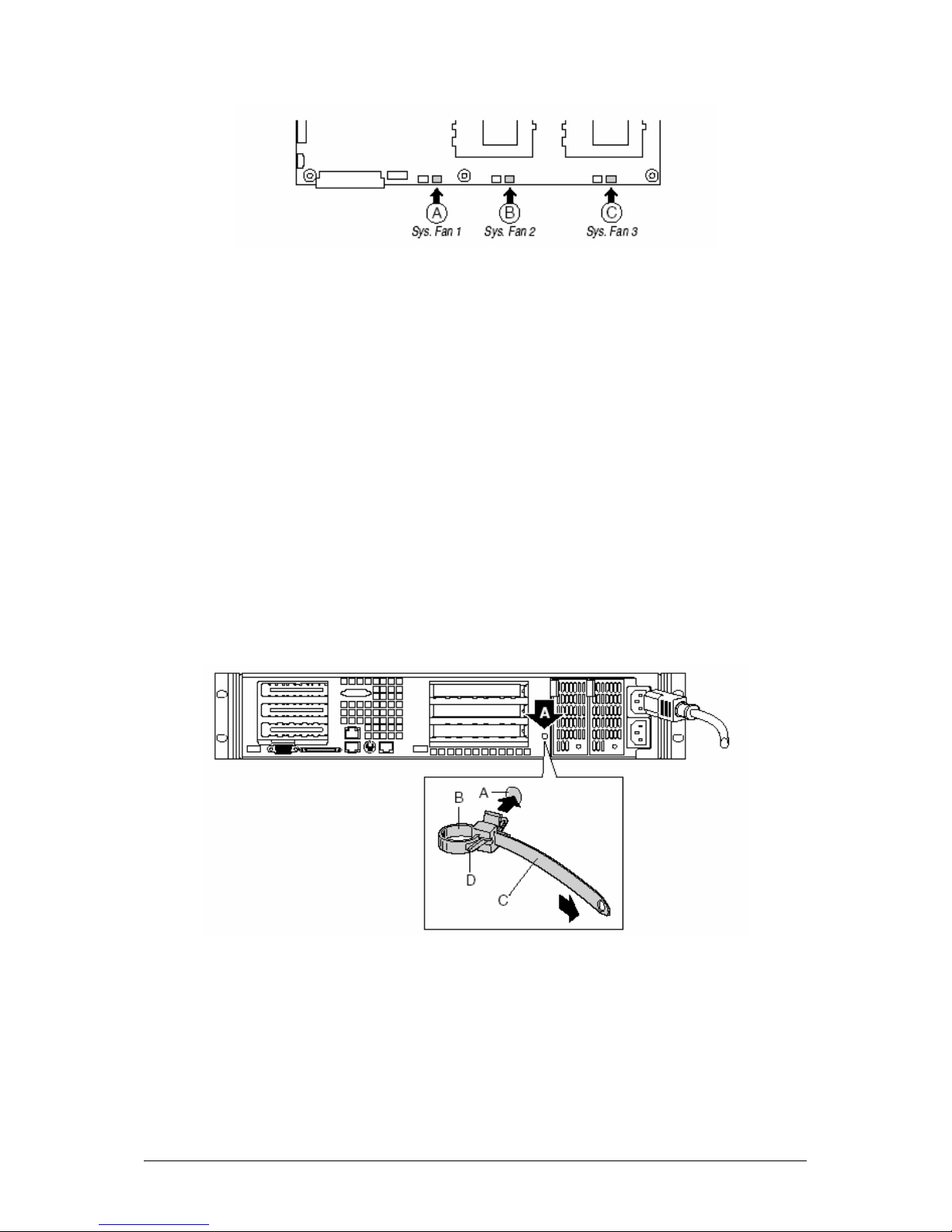
Figure 14: System Fan Connectors
6. Connect the USB cable to the 10-pin USB connector on the server board (Figure
4, Position L on page 13).
Installing the Power Cord and Strain Relief Strap
NOTE: If you wi ll be placing your server in a rack, wait to install the power cord until
after the server is in the rack.
1. Insert the expansion nipple (A) of the strain relief strap into the chassis hole.
2. Plug the power cord into the power supply but not into the power source.
3. Insert the power cord into the plastic loop (B) of the strain relief.
4. Pull the plastic band (C) until it tightens around the power cord.
To release the plastic loop and free the cord, squeeze the release lever (D).
Figure 15: Installing the Power Cord
Viglen SX220 User Guide 35
Page 37

Adding Components to the Server Board
After installing the serv er b oa rd, you m ust add the desired number of processors and
memory DIMMs.
NOTE: Once the server board and its components are installed, you are done
assembling the system unless you have optional peripherals or add-in
cards you wish to install. If you need to install these c omponents, continue
on to the next section. Otherwise, insta ll the cover and bezel and continue
on to Chapter 5, “Installing the System in a Rack” found on page 51.
Installing Processors
1. Observe the safety and ESD precautions at the beginning of this chapter.
2. Raise the locking bar on the socket.
3. Observe the safety and ESD precautions at the beginning of this chapter.
4. Raise the locking bar on the socket.
Figure 16 Raising the Locking bar on the socket
5. Aligning the pins of the processor with the socket, insert the processor into the
socket.
6. Lower the locking bar completely.
Viglen SX220 User Guide 36
Page 38

Figure 17: Inserting the Processor
7. Following the instructions package d with the applicator, apply therm al grease to
the processor.
8. Position the heat sink slot (2) above the socket/processor slot (3).
9. Aligning the raised metal surfaces, place the heat sink on top of the processor.
10. Install the heat sink clip with pin (1) inserted into slot (2).
Viglen SX220 User Guide 37
Page 39

Figure 18: Installing t he Heatsink
A. Heat sink retention clip
B. Heat sink
C. Socket and processor
CAUTION!
Use care when closing the locking lever—do it slowly.
11. Slowly close the locking lever (A) until it contacts tab (B), see Figure 19.
Viglen SX220 User Guide 38
Page 40

Figure 19: Locking Heatsink Lever
12. Install the fan on the processor heat sink making sure that it is seat ed flat on the
heatsink.
13. Connect the fan to (A) if it is on the primary processor or to (B) if it is on the
secondary processor.
Figure 20: Processor Fan Connectors
Viglen SX220 User Guide 39
Page 41

Install the Processor T erm i nator
If you are installing only one processor, you must install a terminator in the
secondary processor socket (A). If you are installing two processors, skip this
section.
1. Raise the locking bar (B) on the socket.
2. Aligning the two corner marks on the terminator with the handle-side of the
socket (C), insert the terminator into the socket.
Lower the locking bar completely (D).
Figure 21: Installing the Processor Terminator
Memory
Only PC-133 compliant SDRAM is supported by the SX220 server board. Install from
128 MB to 6 GB of registered, ECC memory, using up to six DIMMs.
DIMMs must be installed in pairs and in the following order: 1a and 1b, 2a and 2b, 3a
and 3b.
Installed DIMMs must be the same speed and must all be registered. For a list of
supported memory, call your ser vice representative.
Viglen SX220 User Guide 40
Page 42

Figure 22: Installing DIMMs
Installing Peripherals
Peripherals and add-in cards are not included in your system and must be
purchased separately. The following sections describe how to install PCI add-in
cards, hard disk drives, a CD-ROM drive/floppy disk, and a tape drive.
Installing a PCI Card on a Riser Card
The riser card near est the chass is sidewall s upports thr ee Low P rofile (LP ) PCI addin cards. The riser card on the chassis centerline supports three full-length, fullheight add-in cards or three LP ca rds (an LP card m ust be equippe d with a stan dard
full-height PCI mounting brack et) .
NOTE: Add-in cards m ust be inst alled o n a ri ser card while t he riser car d is r emoved
from the chassis.
1. Open the retainer clip (A) and remove the filler panel from the rear retention
bracket (B) of the riser card.
2. Insert the PCI card edge connector in the ris er PCI slot (D ) while a lignin g the en d
of the PCI card bracket in opening (C).
Viglen SX220 User Guide 41
Page 43

3. Firmly push the PCI card connector into the riser card slot until it is fully seated.
4. Close the retainer clip (A). Ensure the clip is latched.
Figure 23: Installing a PCI card of the riser
Installing a Riser Card on the Server Board
1. Insert the riser card connector into the server board slot while aligning the tabs on
the rear retention bracket with the holes in the chassis.
CAUTION!
Press the riser card straight do wn into the slot. Tippi ng it into the slot while installing
it may damage the riser card or slot.
2. Firmly press the riser card straight down unti l it is fully seat ed in the se rver board
slot.
Viglen SX220 User Guide 42
Page 44

Figure 24: Installing a Riser Card
Installing a Hard Drive
The server can support up to seven hot s wappa ble hard driv es: six hard drives in the
drive bays, plus one in the flex bay.
CAUTION!
To allow proper airflow and server cooling, all drive bays must contain either a carrier
with a hard drive installed or a carrier with an air baffle installed.
1. If present, remove the front bezel.
2. If the drive carrier is installed in the drive bay, remove it.
3. Remove the air baffle (Figur e 25, A) from the drive carrier by rem oving the four
screws (B) from the slide track (C).
4. Store the air baffle for future reinstallation in the event you must operate your
server without a drive in one of the bays.
Viglen SX220 User Guide 43
Page 45
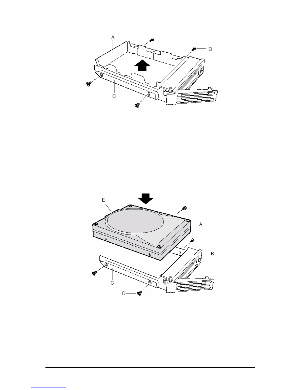
Figure 25: Hard Drive Carrier
5. Remove the hard drive from it s wrapper and place it on an anti -static surface.
6. Set any jumpers and/or switches on the drive according to the drive
manufacturer’s instructions.
7. W ith the drive circuit-side-d own (Figure 26, A ), position the connect or end (E) so
that it is facing the back of the carrier (B).
8. Align the holes in the drive to the holes i n the drive carrier slide tra ck (C), insert
the screws (D) that you previously removed, and attach the carrier t o the driv e.
9. Slide the car rier/drive all the way into the drive bay with the retention l ever in the
fully open position.
10. Push the retention lever closed to secure the carrier/drive in the bay.
Figure 26: Installing the Hard Drive
Viglen SX220 User Guide 44
Page 46
11. Reinstall a carrier/air baffle in any bays where you are not installing a
carrier/drive.
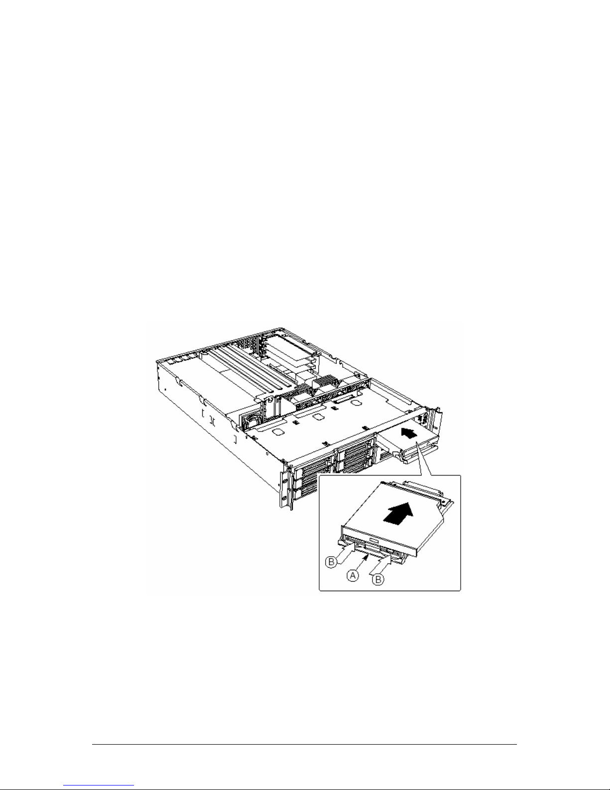
Installing a CD-ROM Drive/FDD Module
The SX220 server is supplied with a CD-RO M drive and a floppy di sk drive already
installed in the Flex Bay. The blow steps will help you to re-install the unit if it has
been removed to make way for an additional SCSI hard disk drive.
1. Remove the filler panel and plug from the front of the chassis.
2. Ensure the handle bar (A) on the front of the module is rotated to the down
position.
3. Insert the mo dule into the flex bay an d slide it back until you feel th e connectors
touch.
4. With your thumbs positioned above the handle bar indentations (B), push the
module in until it locks in place.
Installing a Tape Drive
You may purchase a tape drive and install it in the 3.5-inch drive bay using the
carrier provided. SCSI tape drives are recommended due to the cable length
required. If you install an IDE tape drive, you must install an IDE add-in controller
card. The cable routing will be similar to what is shown for a SCSI tape drive.
Figure 27: Installing a CDROM/FDD Module
Viglen SX220 User Guide 45
Page 47

NOTE: Using the le gacy IDE c onnect or on t he S CB2 s erver board t o sup port a n IDE
peripheral device in the SX220 server is not a supported configuration.
Using this connector in the SX220 server may produc e unreliable operation
of the IDE device and may result in data loss.
If you install a SCSI tape drive, you can connect it one of two ways:
• To the on-board SCS I contr oller. T his req uir es that you connect the backplane
to an add-in RAID or SCSI controller.
• To an add-in SCSI controller board. This allows you to leave the backplane
connected to the on-board SCSI controller.
Mounting the Tape Drive
1. Remove the chassis cover.
2. Remove the blank panel from the bay.
3. Push on the retainer clip at the rear of the carrier (A) to release it from the
chassis.
4. Remove the carrier by sliding it toward the front of the chassis.
5. Set any jumpers and/or switches on your tape drive (B) according to the drive
manufacturer’s instructions.
6. Install the tape drive in the carrier.
7. Insert the carrier/drive assem bly in the empty bay and slide it toward the rear of
the chassis until the retainer clip latches.
Figure 28: Mounting a Tape Drive
Viglen SX220 User Guide 46
Page 48

CAUTION!
Carefully route cables to minimise airflow blockage and cooling problems.
Suggested Tape Drive Cablin g
A peripheral power cable (4 -pin connector) is included in the cabl e output from the
power supply.
Route and connect to the tape drive before the SCSI cable is installed.
Connecting to the On-board SCSI Controller
1. Obtain a SCSI cable with an unfolded length of 26-inches.
2. Flatten the cab le and fold it in half begin ning ab out 1-inch from the t ape drive end
(see Figure 29, A). Continue folding for a distance of about 10-inch es.
3. Fold the cable in half again and secure with electrical tape.
4. Connect the cable to the tape drive (see Figure 30, A) and carefully route the
folded and taped secti on on the chassis floor bet ween the fan assembl y (C) and
the tape drive (A).
5. Connect the cable to the on-board SCSI cont roll er at conn ector (B).
Because the on-board SCSI controller is now unavailable, you will need to install a
PCI add-in card that provides RAID or SCSI control and connect it to the backplane.
Figure 29: SCSI Cable Length Required
Viglen SX220 User Guide 47
Page 49

Figure 30: Onboard SCSI Connector
Connecting to a SCSI Controller on a Full-height PCI Card
1. Obtain a SCSI cable with an unfolded length of 26-inches.
2. Flatten the cab le and fold it in half begin ning ab out 1-inch from the t ape drive end
(see Figure 29, A). Continue folding for a distance of about 10-inc h es.
3. Fold the cable in half again and secure with electrical tape.
4. Connect the cable to the tape drive (see Figure 31, A) and carefully route the
folded and taped secti on on the chassis floor bet ween the fan assembl y (C) and
the tape drive (A).
5. Connect the cable to the SCSI controller (B) on the full-height PCI card.
Figure 31: Connecting to a Full Height PCI SCSI Controller
Viglen SX220 User Guide 48
Page 50

Connecting to a SCSI Controller on a Low Profile PCI Card
1. Obtain a SCSI cable with an unfolded length of 26-inches.
2. Flatten the cable and fold it in half for the full length, leaving ab out 1-inch at each
end (see Figure 32).
3. Fold the cable in half again and secure with electrical tape.
4. Connect the cable to the tape drive (see Figure 33, A) and carefully route the
folded and taped secti on on the chassis floor bet ween the fan assembl y (C) and
the tape drive (A).
5. Connect the cable to the SCSI controller (B) on the low-prof ile PCI card.
Figure 32: SCSI Cable Length Required
Figure 33: Connecting to a half Height PCI SCSI Controller
Installing a COM 1 port in the Rear I/O
Using a standard DH-10 to DB-9 COM cable, you may install a COM 1 port in the
opening provided in th e rear I/O (see Fig ure 3, C, on page 9). C onnect the oth er end
to the COM 1 serial port header on the server board (see Figure 4 on page 13)
Viglen SX220 User Guide 49
Page 51

Installing the Bezel
Place the bezel between the chassis handles and push it toward the front of the
chassis until it snaps into place.
Figure 34: Installing the Front Bezel
Viglen SX220 User Guide 50
Page 52

55.. IInnssttaalllliinngg tthhee SSyysstteemm iinn aa RRaacckk
CAUTION!
ANCHOR THE EQUIPMENT RACK: The equipment rack must be anchored to an
unmovable support to prevent it from falling over when one or more servers are
extended in front of it on slide assemblies. The equipment rack must be installed
according to the manufacturer's instructions. You must also consider the weight of
any other device installed in the rack.
MAIN AC POWER DISCONNECT: You are responsible f or installing an AC power
disconnect for the entire rack unit. This main disconnect must be readily accessible,
and it must be labeled as controlling power to the entire unit, not just to the server(s).
GROUNDING THE RACK INSTALLATION: To avoid the potenti al for an electrical
shock hazard, you must include a thi rd wire safet y grounding conductor with the rack
installation. If server power cords are plugged into AC outlets that are part of the
rack, then you must provide proper grounding for the rack itself. If server power
cords are plugged into wall AC out lets , the s afety grounding conductor in each power
cord provides proper grounding only for the server. You must provide additional,
proper grounding for the rack and other devices installed in it.
OVER CURRENT PROTECTION: The server is designed for an AC line voltage
source with up to 20 am peres of over current prot ection. If the power s ystem for the
equipment rack is installed on a branch circuit with more than 20 amperes of
protection, you must provide supplem ental pr otecti on for the server. If more than one
server is installed in the rack, the power source for each server must be from a
separate branch circuit.
CAUTION!
Temperature: The operating temperature of the server, when installed in an
equipment rack, must not go below 5 °C (41 ° F) or ris e above 35 °C (95 °F). Extr em e
fluctuations in temperature can cause a variety of problems in your server.
Ventilation: The equipment rack must provide sufficient airflow to the front of the
server to maintain proper cooling. It must also include ventilation sufficient to exhaust
a maximum of 1840 Btu's per hour for a fully loaded SX220 server.
It is important to note that this is the maximum, and a minimum or t ypical system
could be much less. You ma y want to calcul ate the BTU/h r more accur ately for your
configuration. An extra 500 BTU/hr over many systems would translate i nto a large
error calculating air conditioni ng capacit y.
Viglen SX220 User Guide 51
Page 53

Removing the Rails
1. Fully extend a rail assembl y (Figure 35). The fi nger t ab (D) for the extension lock
is revealed.
2. Press the finger tab and slide the inside rail (C) from the middle rail (B) until it
completely separates.
NOTE: The middle rail (B) and outer rail (A) cannot be separated.
Figure 35: Removing the Rails
A. Outer rail
B. Middle rail
C. Inner rail
D. Finger tab on extension lock
Attach Inside Rails to Chas sis
1. Posit ion an inside rail (F igure 36, A) along o ne side of the chassis with the finger
tab facing outward and located closer to the rear of the chassis.
2. Align the holes (C) i n the rail with the tabs (D) on t he chassis and place the rail
against the chassis.
3. Slide the rail as far as it will go toward the front of the chassis to engage the tabs.
4. Fasten the rail to the chassis using screw (B).
5. In the same manner, attach the other inside rail to the other side of the chassis.
Viglen SX220 User Guide 52
Page 54

Figure 36: Attaching the Rails
A. Inside rail
B. #6-32 x 3/16-inch screw
C. Attachment hole
D. Attachment tab
E. Attachment hole for cable manager (available from others)
Attach Rail Brackets to Posts
1. Using two screws with washers (Figure 38, A ) , attach on e n ut b ar (B) at the same
height on the inside of each rack post. Do not completely tighten the screws—
leave them loose enough to allow insertion of the brackets in the next step.
2. Insert the slotted foot of a rail bracket between each nut bar an d pos t.
3. Align the face of the bracket foot with the inside ed ge of the rack post and firm ly
tighten the screws.
Figure 37: Attac h ing Ra il Bra c ket s to Po st
A. #10-32 x ½-inch screw with washer
B. Nut bar
C. Washer
Viglen SX220 User Guide 53
Page 55

Attach a Rail Assembly to a Front Bracket
1. Position a rail assembly (middle and outer rails) with its black plastic end caps
toward the rear of the rack and its outer rail closest to the brackets.
2. Align the front screw hole (Figure 38, C) in the outer rail (B) with the threaded
hole (D) nearest the front of the front brack et (A) and f it the rail assem bly into the
front and rear brackets.
3. Slide the middle rail to ward the front (E) until the access ho le (F) in t he m iddle r ail
is aligned with the front screw hole (C) in the outer rail.
4. Insert screw (G) throu gh the access hole and loosely attach th e outer rail to the
front bracket.
5. In a similar manner to steps 2 through 4, install a screw through a slot in the outer
rail and into the rear-m ost threaded hole in the front brack et. Firmly tighten this
screw.
6. Firmly tighten the front screw (G) installed loosely in step 4.
7. In the same manner, attach the other rail assembly to the other side.
Figure 38: Attaching Rail Assembly to Front Bracket
Viglen SX220 User Guide 54
Page 56

A. Front bracket
B. Outer rail
C. Screw hole
D. Threaded hole
E. Not Shown
F. Access hole
G. #6-32 x 3/16-inch screw
Attach a Rail Assembly to a Rear Bracket
1. Slide the middle rail toward the front until the rear bracket area is accessible.
2. Attach the rear end of the outer rail (B) to the rear bracket (A) with at least one
screw (C). If possible, attach at two places.
3. In the same manner, attach the other rail assembly to the other side.
Figure 39: Attaching Rail Assembly to Rear Bracket
A. Rear bracket
B. Outer/middle rail assembly
C. #6-32 x 3/16-inch screw
Install the Chassis on the Rails
1. Fully extend the left and right rails (Figure 7, A) until the extension locks have
engaged and the rails will not push back in. The rail system is now ready to
receive the chassis.
Viglen SX220 User Guide 55
Page 57

Figure 40: Rails Fully Extended
CAUTION!
Lifting and placing the chassis in the rails is a two-person job. If needed, use an
appropriate lif ting device. A fully loaded Viglen SX220 server weighs ap proximately
23.1 kg (51 lbs.).
2. With the chassis front facing you, lift the chassis and carefully insert the rails
attached to the chassis in the extended rails.
3. Slide the chassis toward the rear of the cabinet until the rails lock together.
4. Depress and hold down the finger tabs (Figure 41, A) on both extension locks
while sliding the chassis towards the rear.
Figure 41: Sliding the Chassis towards the rear of t he Rack
Viglen SX220 User Guide 56
Page 58

66.. CCoonnffiigguurraattiioonn SSooffttwwaarree aanndd UUttiilliittyy
This chapter describes the Power-On Self-Test (POST) and server configuration
utilities. The table below briefly describes the utilities.
Table 5: configuration Utilities
Utility Description and brief procedure
BIOS Setup Use for system configuration of onboard resources, setting boot device
Changing Boot Device Priority Use this option to change the boot device priority temporari l y
Adaptec SCSISelect † Utility Use to configure or view the settings of the SCSI host ad apters and
Direct Platform Control (DPC)
Console
System Setup Utility (SSU ) A nd
Client System Setup Utility (CSSU)
FRU/SDR Load Utility Use to update the Field Replacement Unit (FRU) and Sensor Record
BIOS Update Utility Use to update the BIOS or recover from a corrupted BIOS update.
Firmware Update Utility Use to update BMC flash ROM or other firmware.
priority, or setting system security options.
You can move the CMOS jumper on the system board fr om the default
setting (Protect CMOS memory) to the Clear setting; this will allow most
system configurations to boot.
permanently.
onboard SCSI devices in the system.
Use to access and monitor the server remotely.
Use for viewing and configuring server managem ent options, viewing
the system event log (SEL), se tting boot device priority, or setting
system security options.
The SSU can ru n eith er from t he configuration software CD or from a set
of bootable diskettes. You ca n create the diskettes fr om the CD.
The CSSU is run from the service partit ion via the DPC console. It
provides the same functional ity as the SSU, but from a remote console.
Information entered via the SS U/CSSU overrides information entered
via BIOS Setup.
(SDR) flash components.
NOTE: You must run the FRU/SDR Load utility whenever BMC is
updated or if you change your processors.
Hot Keys
Use the keyboard’s numeric pad to enter numbers and symbols.
Table 6: Hot Keys
To do this: Press these keys
Clear memory and reload the
operating systemthis is a system
reset.
Enter the Adaptec SCSI Utility
during POST.
Enter the Promise Technology IDE
RAID Utility.
Enter BIOS Setup during POST. <F2>
Abort memory test during POST . <ESC> (Press while BIOS is updating memory size
Display a menu for selecti ng the
boot device.
<Ctrl+Alt+Del>
<Ctrl+A> (SCSI model only)
<Ctrl+F> (ATA model only)
on screen.)
<ESC> (Pre ss a nytime after memory check.)
Viglen SX220 User Guide 57
Page 59

To remove the splash screen. <ESC>
Power-On Self-Test (POST)
Each time you turn on the system, POST starts running. POS T checks the server
board, processor, mem ory, keyboard, and most inst alled peripheral devices. Duri ng
the memory test, POST displays the amount of memory that it is able to access and
test. The length of time neede d to test memory depends on th e amount of memory
installed. POST is stored in flash memory.
1. Turn on your video monitor and server. After a few seconds POST begins to run.
2. After the memory test, thes e scree n prompt s and messages ap p ear:
Press <F2> key if you want to run SETUP
3. If you do not press <F2> and do NOT have a device with an operating system
loaded, the above message remains for a few seconds while the boot process
continues, and the system beeps once. Then this message appears:
Operating system not found
If you do not press <F2> and DO have an operating system loaded, the boot
process continues, and this message appears:
Press <Ctrl><A> to enter SCSI Utility
4. Press <Ctrl+A> if there are SCSI devices install ed. W hen the utilit y opens, follo w
the displayed instructions to configure the onboard SCSI host adapter settings
and to run the SCSI utilities. If you do not ent er the SCSI utility, the boot proc ess
continues.
5. Press <Esc> during POST to pop up a bo ot menu when POST finishes. From
this menu you can choose the boot device or enter BIOS Setup.
After POST completes, the system beeps once.
What appears on the screen aft er this depends on whether you have an operating
system loaded and if so, which one.
If the system halts before POST completes running, it emits a beep code indicating a
fatal system error that re quires imm ediate att enti on. If PO ST can display a m essage
on the video display screen, it causes the speaker to beep twice as the message
appears.
Note the screen display an d write down the beep code you hear; this information is
useful for your service representative. For a listing of beep codes and error
messages that POST can generate, see the “Solving Problems” chapter in this
manual.
Viglen SX220 User Guide 58
Page 60

Using BIOS Setup
This section describes the BIOS Setup options. Use Setup to change the server
configuration defaults. You can run Setup wit h or without an op erating system being
present. Setup stor es m ost of the conf iguration values in batt ery backed C MOS; t he
rest of the values are s tored in flash m emory. The values take ef fect when you boot
the server. POST uses these values t o c onfigure the hardware; if the values and t he
actual hardware do no t agree, POST generates an error m essage. You must then
run Setup to specify the correct configuration.
Record you Setup Settings
If the default values ev er need t o be r estore d (af ter a CMOS clea r, for ex ample), you
must run Setup again. Referring to the worksheets could make your task easier.
If You Cannot Access BIOS Setup
If the diskette drive is misconfigure d so that you cannot access it to run a utility from
a diskette, you ma y need t o clear C MOS me mor y. You will n eed to o pen t he se rver,
change a jumper setting, use Setup to check and set diskette drive options, and
change the jumper back. For a step-by-step proce dure, see Chapter 9, under the
heading, “CMOS Jumper.”
Setup Menu
Table 7: Setup Menu
To: Press
Get general help <F1> or <Alt+H>
Move between menus ← →
Go to the previous item ↑
Go to the next Item ↓
Change the value of an item + or -
Select an item or display a submenu <Enter>
Leave a submenu or e xit Setup <Esc>
Reset to Setup defaults <F9>
Save and exit Setup <F10>
When you see this: What it means
An option is grayed out and not
accessible
The rest of this section lists the f eatures that are dis played onscreen aft er you press
<F2> to enter Setup. Not all of the option choices are described, because (1) a f ew
are not user selectabl e but are displayed for your inf ormation, and (2) many of the
choices are relatively self explanatory.
You cannot change or config ure the option in that menu screen
for one of the following reasons:
• The option is auto-configured or auto-detect ed.
• The field is informational only.
• The field is password pr otect ed and is accessible
only by the User or Administrator
Viglen SX220 User Guide 59
Page 61

Main Menu
You can make the foll owing selections on the Main Menu itself. Use the submenus
for other selections.
Table 8: Main Menu Features
Feature Choices Description
System Time HH:MM:SS Sets the system time
System Date MM/DD/YYYY Sets the system date
Diskette A
Diskette B
Hard Disk Pre-Delay
Primary Master <Enter> Enters submenu
Primary Slave <Enter> Enters submenu
Processor <Enter> Enters submenu
Language
Disabled
1.44/1.25 MB
Disabled
1.44/1.25 MB
Disabled
3 Seconds
6 Seconds
9 Seconds
12 Seconds
15 Seconds
21 Seconds
30 Seconds
English (US)
Français
Deutsch
Italiano
Español
Primary Master/Slave Submenu
Table 9: Primary Master/Slave Submenu Features
Feature Choices Description
Type
Multi-Sector
Transfers
LBA Mode Control
PIO Mode
Ultra DMA Mode
None
Auto
Disabled
2, 4, 8, or 16
sectors
Disabled
Enabled
Standard
1, 2, 3, 3/DMA 1,
4, 4/DMA 2
Mode 2
Mode 4
Processor Settings Submenu
Table 10: Processor Settings Submenu Features
Feature Choices Description
Processor Type N/A Reports type of processor(s) installed in system.
Processor POST Speed N/A Reports the speed of the processor measured at POST.
Selects the diskette type
Selects the diskette type
Adds a delay before first access of the hard drive
Selects which language BIOS displays
Informs the system to ignore this drive.
Allows the system to attempt auto-detection of the drive
type.
Determines the number of sectors per block for
multisector transfers.
For Type Auto, this field is informational only.
For Type Auto, this field is informational only.
Displays the method for moving data to/from the drive.
This field is informati onal only.
Viglen SX220 User Guide 60
Page 62

Processor Retest
Processor Serial Number
Processor 1 CPU ID N/A Reports Stepping for Processor 1.
Processor 1 L2 Cache Size N/A Reports L2 Cache Size for Processor 1. This feature does
Processor 2 CPU ID N/A Reports Steppi ng for Processor 2.
Processor 2 L2 Cache Size N/A Reports L2 Cache Size for Processor 2. This feature does
Disabled
Enabled
Enabled
Disabled
Select yes for the BIOS to clear historical processor status
and retest all processors on the next boot.
If enabled, the system records the serial number of each
processor.
not appear if processor 1 is absent or disabled.
not appear if processor 2 is absent or disabled.
Advanced Menu
You can make the following selections on the Advanced Menu itself. Use the
submenus for the three other selections that appear on the Advanced Menu.
Table 11: Advanced Menu Features
Feature Choices Description
PCI Configuration Memory P ress
<Enter>
Peripheral Configuration Press
<Enter>
Configuration Advance d Press
<Enter>
Chipset Control Reset Press
<Enter>
Configuration Data
Plug & Play O/S
NumLock
No
Yes
No
Yes
Off
On
PCI Configuration Submenu
Table 12: PCI Configuration Submenu Features
Feature Choices Description
On-board SCSI Controller <Enter> Selects sub-menu
On-board LAN #1
Controller
On-board LAN #2
Controller
On-board VGA Controller <Enter> Selects sub-menu
Riser Card Override
PCI Slot 1B ROM Enabled
PCI Slot 1C ROM Enabled Used to enable or disable an option ROM that may be
<Enter> Selects sub-menu
<Enter> Selects sub-menu
Enabled
Disabled
Disabled
Enters submenu.
Enters Submenu
Enters Submenu
Enters submenu
Select Yes to clear the system configuration data during
next boot. System automatically resets to No in next boot.
Selecting “No” let s the BIOS conf igure all th e devices
in the system. Selecting “Yes” allows the OS configure
Plug and Play devices.
Enables or disables the “NumLock” function at power up.
This option will only be displayed if a non-Intel chassis
is used. If enabled, all six options for PCI slots will be
displayed if disabled, only two options for PCI slots will
be disp l ay ed
Used to enable or disable an option ROM th at m ay be
present on a PCI add-in card installed in the slot.
In a 2U chassis, options for additional PCI slots PCI
bus B will be displayed
Viglen SX220 User Guide 61
Page 63

Disabled
present on a PCI add-in card installed in the slot
In a 2U chassis, options for addit ional PCI slots PCI
bus C will be displayed
USB Function Subme nu
Table 13: USB Function Submenu Features
Feature Choices Description
USB Function
Enabled
Disabled
Enables the embedded USB controller.
Onboard NIC 1 and 2 Submenu
Table 14: Onboard NIC 1 and 2 Submenu Features
Feature Choices Description
Onboard NIC
Embedded NIC ROM
Enabled
Disabled
Enabled
Disabled
If enabled, the system uses t he embedded NIC.
Enables the device option ROM.
Onboard SCSI Submenu
Table 15: Onboard SCSI Submenu Features
Feature Choices Description
Onboard SCSI
Embedded LVD SCSI ROM
Enabled
Disabled
Enabled
Disabled
Enables or disables embedded le gacy SCSI controller
hardware.
Enables the device expansion ROM
Onboard R-IDE Submenu
Table 16: Onboard R-IDE Submenu Features
Feature Choices Description
Onboard R-IDE
Onboard R-IDE ROM
Enabled
Disabled
Enabled
Disabled
If disabled, the embedded R-ID E devi ce is turned off
and th e device resources are hi dden from the system
If enabled, initialises the embedded R-IDE device
expansion ROM
Onboard Video Subm enu
Table 17: Onboard Video Submenu Features
Feature Choices Description
Onboard Video
Enabled
Disabled
Enables the embedded video c ontrol ler.
Viglen SX220 User Guide 62
Page 64

Peripheral Configuration Submenu
Table 18: Peripheral Configuration Submenu Features
Feature Choices Description
Serial Port 1 Address
Serial Port 2 Address
Serial Port 1 IRQ
Serial Port 2 IRQ
Diskette Controller
Legacy USB Support
Front Panel USB
Disabled
3F8
2F8
3E8
2E8
4
3
Disabled
3F8
2F8
3E8
2E8
4
3
Enabled
Disabled
Disabled
Keyboard Only
Auto
Keyboard &
Mouse
Disabled
Enabled
Used to configure the serial port address. If console
redirection is used, verify that the I/O and IRQ are
identical to values configured in the “Server Setup”
menu.
Used to configure the interrupt for serial port 1.
Used to configure the serial port address. If console
redirection is used, verify that the I/O and IRQ are
identical to values configured in the “Server Setup”
menu.
Used to configure the interrupt for serial port 2.
Used to enable or disable the onboard floppy disk
controller.
Enables support for legacy USB.
Used to enable the USB ports accessed through the
internal USB header found on the baseboard.
Memory Configura tion Submenu
Table 19: Peripheral Configuration Submenu Features
Feature Choices Description
Extended Memory Test
Bank #1
Bank #2
Bank #3
Memory Retest
1 MB
1 KB
Every Location
Disabled
N/A
N/A
N/A
Disabled
Enabled
Extended memory test opti ons run during POST.
Note: the smaller the increment, the longer the test
takes during POST.
Informational screen used to d isplay whether DIMMs
are present in bank #1
Informational screen used to d isplay whether DIMMs
are present in bank #2
Informational screen used to d isplay whether DIMMs
are present in bank #3
If enabled, BIOS will activate and retest all DIMMs on
the next system boot. This option will be automatically
reset to disabled on the next s ystem boot.
Advanced Chipset Control Submenu
Table 20: Advanced Chipset Control Submenu Features
Feature Choices Description
Wake on Ring
Disabled
Enabled
Legacy wake only: Determines the action of the
system when the system power is off and the modem
is ringing.
Viglen SX220 User Guide 63
Page 65

Wake on LAN
Wake on PME
Wake on RTC Alarm
Disabled
Enabled
Disabled
Enabled
Disabled
Enabled
Legacy wake only: Determines the action of the
system when a LAN wake up event occurs.
Legacy wake only: Determines the action of the
system when a PCI Power Management E nable wake
up event oc c u r s .
Legacy wake only: Determines the action of the
system when a RTC Alarm Wake up event occurs.
Security Menu
You can make the following selections on the Security Menu itself. Enabling the
Supervisor Password f ield requires a password for entering S etup. The passwords
are not case-sensitive.
Table 21: Security Menu Features
Feature Choices Description
User Password is
Administrator Password is Installed
Set Administrative
Password
Set User Password
User Access Level Limited
Password on Boot Disabled
Secure Mode Timer 1 minute
Secure Mode Hot Key
(CTRL-ALT- )
Secure Mode Boot Disabled
Video Blanking Disabled
Power Switch Inhibit Disabled
Installed
Not Installed
Not Installed
Press <En t e r>
Press <En t e r>
No Access
View Only
Full
Enabled
2 minutes
5 minutes
10 minutes
20 minutes
60 minutes
120 minutes
Z
L
Enabled
Enabled
Enabled
Informational Only.
Informational Only.
When the <Enter> key is pressed, a p assword prompt
appears. Press ESC key to abort. Once set, this can
be disabled by setting it to a null string or by clearing
password jumper on server board.
When the <Enter> key is pressed, a p assword prompt
appears. Press ESC key to abort. Once set, this can
be disabled by setting it to a null string or by clearing
password jumper on server board.
Sets the User access level for various BIOS setup
functions.
If your password is set and enabled, the system
prompts you for a password before it boots.
Period of PS/2 keyboard and/or mouse inactivity
specified for secure mode to activate. A password is
required for secure mode to function. This option only
appears on the screen after a “user” password has
been entered.
Key assigned to invoke secure mode f eat ures cannot
be enabled unless at least one password is set. This
option only appears on the screen after a “user”
password has been entered.
System boots in secure mode. The user must enter a
password to unlock the system . This option only
appears on the screen after a “user” password has
been entered.
Blank video when secure mode is activated. A pass
word is required to unlock the system. This option only
appears on the screen after a “user” password has
been entered.
When enabled, the power swit ch is inoperable.
This option only appears on the screen after a “user”
password has been entered.
Viglen SX220 User Guide 64
Page 66

Server Menu
Table 22: Server Menu Features
Feature Choices Description
System Management Press <Enter> Enters Submenu.
Console Redirection Pres s <Enter> Enters Su bmenu.
Event Log Redirection Press <Enter> Enters Submenu
Service Boot Enable
Assert NMI on PERR Disabled
Assert NMI on SERR Disabled
FRB-2 Policy Disable BSP
BMC IRQ Disabled
After Power Failure Stays Off
Temperature Sensor Disabled
POST Error Pause Disabled
Platform Event Filter ing D isabled
Disable
Enabled
Enabled
Do not Disable
BSP
Retry 3 Ti m e s
IRQ 5
IRQ 11
Last State
Power On
Enabled
Enabled
Enabled
Server Redirecti on S u bm enu
Table 23: Server Redirection Submenu Features
Feature Choices Description
Board Part N umber
Board Serial Number
System Part Number
System Serial Number
Chassis Part Number
Chassis Serial Number
BIOS Revision BMC
Revision Primary HSBP
Revision
N/A Information field only
N/A Information field only
N/A Information field only
N/A Information field only
N/A Information field only
N/A Information field only
N/A Information field only
N/A Information field only
N/A Information field only
Console Redirection S u bm enu
Table 24: Console Redirection Submenu Features
Feature Choices Description
Serial Console Redirection Disabled
Serial Port
Enabled
COM1 3F8 IRQ4
If enabled, server boots directly to System
Management.
If enabled, PCI bus parity error (PERR) routes to NMI.
If enabled, PCI bus system err or (SERR) routes to
NMI.
Controls the policy of the FR B-2 timeout. This option
determines when the Boot Strap Processor (BSP)
should be disabled if an FRB-2 error occurs.
Sets the BMC IRQ.
Determines the mode of operation if a power loss
occurs.
If enabled, the system will not boot if the ambient
system temperature is outside the range specified in
the Sensor Data Record (SDR).
If enabled, the system will wait for user intervention on
critical POST errors.
Enable/Disable triggers for system sensor events
inside the Baseboard Management Controller (BMC).
If enabled, BIOS uses the specified serial port to
redirect the console to a remote ANSI terminal.
Enabling this option will disable the Quiet Boot option.
Serial port and IRQ designat ed for server
Viglen SX220 User Guide 65
Page 67

Baud Rate
Flow Control No flow control
COM2 2F8 IRQ3
9600
19.2k
38.4k
115.2k
CTS/RTS
XON/XOFF
CTS/RTS + CD
management features. Make s ure t hese values are
identical to those of Serial P ort A and B in t he
Peripheral Configuratio n Setup menu.
Console Redirection, when enabl ed, uses the baud
rate specified. When the Direct Platform Control
(DPC) shares the COM port as console redirection,
set the baud rate to 19.2k to match DPC baud rate,
unless the autobaud feature is used.
None, disallows flow control. CTS/RTS is hardware
based flow control. XON/XOFF is software flow
control. CTS/RTS +CD is hardware based plus
carrier-detect flow control. When DPC is sharing the
COM port as Console Redirection, s et t he fl ow control
to XON/XOFF or XON/XOFF+CD depending whether
a modem is used.
Event Log Configura tion Submenu
Table 25: Event Log Configuration Submenu Features
Feature Choices Description
Clear A ll Event Logs
Event Logging
Critical Event Logging Enabled
No
Yes
Enabled
Disabled
Disabled
Setting this option to YES will clear the DMI event log
after a system reboot.
When enabled, all syst ems events are logged.
If enabled, BIOS will detect and log events for system
critical errors.
Critical errors are fatal to system operation. These
errors include PERR, SERR, ECC, Memory errors and
NMI.
Boot Menu
Table 26: Boot Menu Features
Feature Choices Description
Quiet Boot
Boot Device Priority
Hard Drive
Removable Devices
ATAPI CDROM Drives Press <Enter> Enters submenu.
Boot Device Priority Submenu
Use the up or down arrow keys t o select a device; the n press the < +> or <-> keys to
move the device higher or lower in the boot priority list.
Disabled
Enabled
Disabled, displays normal POST m essages.
Enabled, displays OEM Logo instead of POST
messages. Enabling this opti on disables serial
redirection.
Press <Enter> Enters submenu.
Press <Enter> Enters submenu.
Press <Enter> Enters submenu.
Viglen SX220 User Guide 66
Page 68

Table 27: Boot Device Priority Submenu Features
Boot Priority Device Description
1st Boot Device
2nd Boot Device
3rd Boot Device
4th Boot Device
Removable
Hard Dri ve
Devices ATAPI CDROM Driv e
Intel Boot Agent
version 4
Attempts to boot from a removable media device.
Attempts to boot fr om a hard drive device.
Attempts to boot from an ATAPI CD -ROM drive.
Attempts to boot from a network when a network
device controlled by a PXE compliant ROM is
present in the system.
Hard Disk Submenu
For options on this menu, use the up or down arrow keys to select a device. Press
the <+> or <-> keys to move the device higher or lower in the boot priority list.
Table 28: Hard Disk Submenu Features
Feature Choices Description
1. Drive #1 (or actual drive
string)
2. Other bootable cards
(additional entries f or each
drive that has a PnP
header)
Other bootable cards cover all the boot devic es not
reported to the system BIOS thro ugh BIOS Boot
Specification mechanisms. It may or may not be
boota ble, and may not correspond to a ny devi ce.
Other bootable cards cover all the boot devic es not
reported to the system BIOS thro ugh BIOS Boot
Specification mechanisms. It may or may not be
boota ble, and may not correspond to a ny devi ce.
Removable Devices Subm enu
For options on this menu, use the up or down arrow keys to select a device.
Table 29: Remo vabl e De vi ces Submenu Feature s
Feature Choices Description
Lists Bootable Removable
devices in the system.
Select one of the
detected devices
This list includes legacy 1. 44-MB floppy drives and
120-MB floppy drives.
ATAPI CDROM Drives Submenu
For options on this menu, use the up or down arrow keys to select a device.
Table 30: ATAPI CDROM Drive Submenu Features
Feature Choices Description
Lists Bootable Removable
devices in the system.
Select one of the
detected devices
This includes any ATAPI CDROM Drive installed
Viglen SX220 User Guide 67
Page 69

Exit Menu
You can make the following selections o n the Exit Menu. Select an option usi ng the
up or down arrow keys. Press <Ent er> to run the option. Pressing <Esc> does not
exit this menu. You must select one of the items from the menu or menu bar to exit.
Table 31: Exit Menu Features
Feature Choices Description
Exit Saving Changes
Exit Disca rd i ng Changes
Load BIOS Setup Defaults
Load Custom Defaults
Save Custom Defaults
Discard Changes
Exits and saves changes to CMOS.
Exits without saving changes to CMOS. BI OS Setup
utility is exited and POST continues.
Loads factory default values for all BIOS Setup data.
Loads custom defaults saved from previous Custom
Save.
Saves new BIOS settings and stores them as custom
default values.
Discards any changes made to BIOS settings and
restores pr evious sett ings.
Temporarily Changing the Boot Device Priority
During POST, you can chang e the boot device priority for the c urrent boot process.
The changes are not saved for the next boot process.
1. Boot the server.
2. At any time during POST, press <Esc>. When POST completes, a popup Boot
menu dis p l ays .
3. Use the arrow keys to highlight the device you want the server system to boot
from first. For example, if you want the server system to boot from the CD-RO M
first, you select "CD-ROM Drive."
NOTE: One of the selections on the popup Boot menu is "Enter Setup.” Selecting
this option brings you into t he BIOS Setup. For more informati on about the
BIOS Setup, see “Using BIOS Setup” on Page 59.
4. Press <Enter>.
5. The boot process continues. When finished, a system prompt displays.
Running the Adaptec SCSISelect Utili ty
Each host adapter includes an onboard SCSISelect configuration utility that allows
you to configure/view the settings of the host adapter and devices in the server.
The system finds the Adaptec AIC-7899 SCSI host adapter and displays the
message Adaptec AIC-7899 SCSI BIOS V x.xxx where x.xxx is the version number
of the SCSISelect utility. Pressing <Ctrl+A> at this time allows you to configure the
Adaptec AIC-7899 SCSI host adapter.
Viglen SX220 User Guide 68
Page 70

When to Run the Adaptec SCSISelect Utility
Use the SCSISelect utility to:
• Change default values
• Check and/or change SCSI device settings that may conflict with those of
other devices in the server
• Do a low-level format on SCSI devices installed in the server
Running the SCSISelect Utility
1. When this message appears on the video mo nitor:
<<<Press <Ctrl><A> for SCSISelect(TM) Utility>>>
2. Press <Ctrl+A> to run the utility. When the main menu for the host adapter
appears, choose the device that you want to configure—each SCSI bus accepts
up to 15 devices.
Use the following keys to navigate through the menus and submenus:
Table 32: SCSISelect Navigation Keys
Press To
ESC Exit the utility
Enter Select an option
Up-Arrow Return to a previous option
Down-Arrow Move to the next option
F5 Switch between color and monochrome
F6 Reset to host adapter defaults
Configuring the Adaptec AIC-7899 SCSI Adapter
The Adaptec AIC-7899 SCSI adapter has two busses. Select the bus from the
following menu:
Figure 32: Main Menu
Main Menu Options
You have an AIC-7899 adapter in your s yst em. Move
the cursor to the bus:device:channel of the one for
configuration and press <Enter>.
<F5> - Toggle color/monochrome
After selecting the bus, the following menu displays:
Table 33: Menu for each SCSI Channel
Host Adapter Option Comment
AIC-7899 at
Bus:Device:Channel
01:06:A (or 01:06:B)
Configure/View Host
Adapter Settings
Bus:Device:Channel
01:06:A
01:06:B
Press <Enter> to view the Configur ation Menu.
Viglen SX220 User Guide 69
Page 71

SCSI Disk Utilities Press <Enter> to view the SCSI Disk Utilities
Menu. This menu allows you to format hard
disks and/or verify disk media.
When you are finished, press <Esc> and make your selection from the following
menu:
Table 34: Exit Menu
Feature Option Comment
Exit Utility? Yes
No
When you finish configuring your SCSI devices, press <Esc>. Then select
Yes and press <Enter>. When this message appears:
Pleas e pres s any key to reboot
Press any key, and the server r eboots.
Running the Promise FastBuild Utility
This utility is only found on the SCB2 ATA model only.
The Promise ATA-100 host adapter is configured using the FastB uild†configuration
utility that allows you to co nfigure/vi ew the sett ings of the host adapter and set RAID
configurations.
When to Run the Promise FastBuild Utility
Use the FastBuild utility to:
• Define a RAID array
• Delete a RAID array
• Restore a RAID array
Running the Promise FastBuild Utility
1. When this message appears on the video mo nitor:
<<<Press <Ctrl><F> to enter FastBuild (TM) Utility>>>
2. Press <Ctrl+F> to run the utility.
Direct Platform Control (DPC) Console
Direct Platform Control (DPC) Console is part of Intel Server Control. Direct Platform
Control is a server management application that supports remote system
management via LAN, or a n RS-232 serial connection to th e server COM2 port ove r
a modem or a direct serial cable. The Dir ect Platform Control Console provi des the
ability for remote m anagement of Intel serv ers via modem or LAN with a ca pabilit y to
run DOS-based programs.
Viglen SX220 User Guide 70
Page 72

DPC console runs on a client workstation. It communicates with a server by:
• Accessing the server management capabilities of the on-board NIC
• A Windows 2000 compatible modem.
• An RS-232 connection to the server COM2 port.
DPC Console is independent of the server operating system.
Even when the server is off, you ca n use DP C Conso le t o verif y the st ate of a s erver
or diagnose a problem with the server hardwa re. DPC console featur es allow you to:
• Establish connection to remote servers
• Server Control: po wer on, power off, and reset operations
• Retrieve and display entries in the System Event Log (SEL)
• Retrieve and display Sensor Data Records (SDR)
• Retrieve and display Field Replaceab le Unit (FRU) information
• Retrieve and display current Remote Se ns or Access (RS A ) inform ation
• Access a phonebook for remote connection management
• Remote control of the service partition
• File transfer from / to the server
DPC Console Modes of Op era tio n
There are three DPC console modes of operation:
• EMP mode. Access the DPC console features using the DPC console
window menus and/or toolbar. Active when a connection is established
through the EMP port.
• DPC over LAN mode. Access the DPC console features using the DPC
console window menus and/or toolbar. Active when a connection is
established through the LAN.
• Re-direct mode. Active when the server is running BIOS console
redirection. In this mode, the DPC console launches a separate window.
The window operates as an ANSI terminal and communicates with the
server through the port . Character-based commands you type in the DPC
Viglen SX220 User Guide 71
Page 73

Console go directly to the server, and the DPC Console displays the text
that you would normally see on the server console.
To use this mode, you must configure the Console Redirection option of
BIOS Setup for R e-dir ect m od e. E na bli n g C ons ol e Redirection requires t hat
the Boot Time Diagnostics Screen be Enabled in BIOS Setup. If the
redirection window does not displa y information, the Console Redirection is
either incorrectly configured or disabled, the EMP is disabled in BIOS Setup,
or the server is in protected mode. For DPC to function, the server must
NOT be in graphics mode.
If the DPC console fails to con n ect in EMP within 10 seconds an d th e server
can operate in Re-direct mode, a prompt is displayed with the option to
switch to Re-direct mode.
• Service Partiti on mode. Entered when the serv er reboots from the service
partition and the DPC Console has successfully connected to the server
through a modem. This mode allows running of DOS-based program s that
are stored on the service partition and transferrin g of files.
Running the DPC Console
For more information about setting up and running the DPC Console, see the
document named "ENUDPCUG.pdf.” This document is in the Manuals\SrvMgmt
directory on the server software kit accompanying the SCB2 serv er board.
Using the System Setup Utility
The System Setup Utilit y (SSU) is located on the SCB2 System R esource CD-ROM
shipped with the server boar d. The SSU provides a graphical user interface (GUI)
over an extensible fra mework for server configuration. For t he SCB2 systems, the
SSU framework supports the following functions and capabilities:
• Allows configuration of Sever Management options
• Allows you to specify boot device order an d system securit y options
• Permits viewing and clearing of the system’s critical event log
• Allows troubleshooting of the server when the OS is not operational
• Allows you to view the system’s Sensor Data Records and Field
Replaceable Unit information
Viglen SX220 User Guide 72
Page 74

What You Need to Do
You can run the SSU directly from the SCB2 Server Software Kit CD-ROM by
booting the server system to the CD and selecting “Utilities” or from a set of DOS
diskettes.
If you choose to run the SS U from a set of DOS diskettes, you must create the SSU
diskettes from the SCB2 Resource CD-ROM by booting to the CD-ROM and
selecting “Create Diskettes.” Alternatively, if you have a Windows based
workstation; you can insert the CD into that system and create diskettes from the
“Utilities” menu of the graphical user interface.
If your diskette drive is disabled, or impr operl y configur ed, you must use BIOS Setup
to enable it so that you can use the SSU. If necessary, you can disable the drive
after you exit the SSU. Information entered using the SSU overrides any entered
using BIOS Setup.
Running the SSU
Running the ssu.bat file provided on the SSU media starts the SSU. If the server
boots directly from the SSU media, the ssu.bat file automatically runs. If it boots
from a different media, you can start the SSU manually or by another application.
When the SSU starts in the local execution mode (the default mode), the SSU
accepts input from the keyboard and/or mouse. The SSU presents a VGA based
Graphical User Interface (GUI) on the primary monitor.
The SSU runs from writable, n on-writable, rem ovable, and non-removabl e media. If
you run the SSU f rom non- writable me dia, you c annot save user pr eference sett ings
(such as screen colours).
The SSU supports the ROM-DOS® V6.22 operating system. It may run on other
ROM-DOS-compatible operating systems but they are not supported. The SSU will
not operate from a “DOS box” running under an operating system such as Windows.
Starting the SSU
SSU consists of a collection of task oriented modules plugged into a common
framework called the Application Framework (AF). The Application Framework
provides a launching point for individual tasks and a location for setting
customisation information. For f ull functionality, the SSU requires the availabili ty of
the AF.INI, AF.HLP, plus any .ADN files and their associated .HLP and .INI files.
1. Turn on your video monitor and your system.
2. There are two ways to start the SSU:
Viglen SX220 User Guide 73
Page 75

a. After creating set of three SSU diskettes from the CD: Insert the first SSU
diskette in drive A, and press the res et butt on or <Ctrl+Alt+Del> to reboot your
server from the diskette.
b. Directly from the SCB2 Serve r Software Kit CD-ROM: Insert the CD into you r
CD-ROM drive and press the reset button or <Ctrl-Alt-Del> to reboot. When
prompted to do so, pr ess <F2> to enter BIOS Setup. From the Boot Menu,
select the Boot Device Priority option and then select CD-ROM as your
primary boot device. Save t hose settings and exit BIOS Setup. The server
will boot from the CD-ROM and display a menu of options. Follow the
instructions in the menu to start the SSU.
3. When the SSU title appears on the screen, press <Enter > to continue.
4. The mouse driver loads if it is available; press <Enter> to continue.
5. This message appears:
Please wait while the Application Framework loads....
6. W hen the main window of the SSU appears, you can customise your interface
before continuing. (See Figure 42).
Customising the SSU
The SSU lets you custom ise your interface according to your preferences. The AF
sets these preferences and saves them in th e AF.INI file so that the y take effect the
next time you start the SSU. There are four user customisable settings:
Figure 42: System Setup Utility Main Window
Viglen SX220 User Guide 74
Page 76

• Colour - this button lets you change the default colors associated with
different items on the scre en with predefined color c ombinations. The c olor
changes are instantaneous.
• Mode - this button lets you set the desired expertise level.
novice
intermediate
expert
The expertise level determines which tasks are visible in the Available
Tasks section and what actions each task performs. For a new mode
setting to take effect, you must exit the SSU and restart it.
• Languag e - this button lets you cha nge the strings in the SSU to st rings of
the appropriate language. For a new language setting to take effect, you
must exit the SSU and restart it.
• Other - this button lets you change other miscell aneous options in the SSU.
The changes take effect immediately.
To change the interface default values:
• Use the mouse to click on the proper button in the Preferences section of
the SSU Main window.
OR
• Use the tab and arrow keys to highlight the des ired butt o n, and press the
spacebar or <Enter>.
OR
• Access the menu bar with the mouse or hot keys (Alt + underlined letter).
NOTE: If you run the SSU from non-writable media (like a CD-ROM), these
preferences will be lost when you exit the SSU.
Launching a Task
It is possible to have many tasks open at the same time, although some tasks may
require complete control to avoid possible conflicts. The tasks achieve complete
control by keeping the task as the center of operation until you close the task
window.
To launch a task:
• In the SSU Main window, double click on the task name under Available
Tasks to display the main window for the selected task.
Viglen SX220 User Guide 75
Page 77

OR
• Highlight the task name, and click on OK.
OR
• Use the tab and arrow keys to highlight the des ired butt o n, and press the
spacebar or <Enter>.
MultiBoot Options Add-in
The Multi-boot Add-i n (MBA) provides a n interface f or selecting Init ial Program Load
(IPL) devices. Using the MBA, the user can identify all IPL devices in the system
and prioritise their boot order. On power-up, the BIOS will sequentially attempt to
boot from each device.
Under this window, you can change the boot priority of a device.
1. Select a device.
2. P ress the + button to move it up in the list. Press the - button to move it
down.
Password Add-in
The Password Add-in (PWA) provides security and password support options.
Within the PW A, the user can either set or modify the curre nt system passwords or
update any of the various security options available.
To Set yo ur Passwor d
1. Click on your password button.
2. Enter the password in the first field.
3. Confirm the password by entering it again in the second field.
To Change or Clear you r Pa ssword
1. Click on your password button.
2. Enter the old password in the first field.
3. Enter the new password in the second field (or leave blank to clear).
4. Confirm the password by entering it again in the second fi eld (or leave blank to
clear).
Viglen SX220 User Guide 76
Page 78

Admin Passwo r d Button
The ‘Admin Password’ button allows the user to set or change the administrative
password used by bot h the SSU and the system BIOS. Note that this o ption is not
available if both an adminis trative and a user password are set on the on the s ystem
and only the user passwor d has been provided upon starti ng the SSU. All changes
to the admin password take place immediately.
To Change or Clear the Administr ato r Password
1. Click on the Administrator password button.
2. Enter the old password in the first field.
3. Enter the new password in the second field (or leave blank to clear).
4. Confirm the password by entering it again in the second f ield (or leave blank to
clear).
User Password Button
The ‘User Password’ button allows the user to set or change the user password used
by both the SSU and the system BIOS . All changes to the user pas sword take place
immediately.
To Change or Clear the User Passwor d
1. Click on the User password button.
2. Enter the old password in the first field.
3. Enter the new password in the second field (or leave blank to clear).
4. Confirm the password by entering it again in the second field (or leave blank to
clear).
Options Button
The ‘Options’ button allows the user to set or change any of the various security
options available on the system platform. The window created by the ‘Options’
button includes ‘Save’, ‘Close’, and ‘Help’ buttons.
Under this window, you can set the other security options:
• Hot Key—Set a key seq uence that, when pressed, will drop the server into
secure mode.
Viglen SX220 User Guide 77
Page 79

• Lockout Timer—Set an int erval that, if no activity takes plac e, it will drop t he
server into secure mode.
• Secure Boot Mode—Forc e the serv er to boot directly into secure mode.
• Video Blanking—Turn off the video when the server is in secure mode.
• Floppy Write—Control access to the diskette drive while the server is in
secure mode.
• Reset/Power S witch Locking—Co ntrol the power and reset buttons while t he
server is in secure mode.
Close Button
The ‘Close’ button exits the PWA and returns the user to the SSU.
Help Button
The ‘H e lp’ button in vokes the SSU h e lp subsyst em.
SEL Manager Add-in
The System Event Log (SEL) Manager Add-In provides services to allow users to
view the system event log stored on the server management storage device of a
server. The SEL Manager provides suppo rt for the user to pe rform the following:
• Examine all system event l og entries, st ored in th e non-v olatil e stora ge ar ea
of the server.
• Examine system event log entries from a previously stored file.
• Save the system event log entries to a file.
• Clear the system event log entries from the non-volatile storage area.
The SEL Manager has the following menus:
File
The Fi le menu has th e follo wing opt ions:
• Open: View data from a previously saved SEL file.
• Save As: Save the currently loaded SEL data to a file.
• Exit: Quits the SEL Viewer.
Viglen SX220 User Guide 78
Page 80

SEL
The SEL menu has the following options:
• Properties: Displays information about the SEL. These fields are display
only.
• Clear SEL: Clears the SEL data from the BMC.
• All Events: Displays the current SEL data from the BMC.
• Reload: Allows the user to re-load the SEL entries from the server.
Help
The Help menu has the following option:
Help Topics: Displays the SEL Manager Version information.
FRU Manager Add-in
The FRU Manager is an add-in module, which allows users to view the FRU
inventory areas on the server machi ne. The FRU Manager will h ave the functionality
to display the FRU inventory areas in an interpreted, easy-to-understand textual
form. The add-in allows users to do the following operations:
1. Examine any of the individual FRU inventory areas.
2. Examine FRU inventory areas from a previously stored file.
3. Save the FRU inventory areas to a file in either text.
The FRU Manager has the following menus:
File
The Fi le menu has th e follo wing opt ions:
• Load: View data from a previously saved FRU file.
• Save: Saves the currently loaded FRU data to a file.
• Save As: Saves the currently loaded FRU data to a file.
• Exit: Quits the FRU Viewer.
Viglen SX220 User Guide 79
Page 81

View
The View menu has the following options:
• FRU Info: Displays information about the FRU. These fields are display
only.
• All FRU Areas: Displays the current FRU data from the BMC.
• By Devi ce Type: Brin gs up a popup m enu that allows you to view only t he
data from a certain device type.
Settings
The Settings menu has the following options:
• Display HEX/Verbose: Toggles between the Hex/interpreted mode of
displaying the FRU records.
• Output Text/Bin ar y: Determines wheth er FRU data will be saved to the f ile
(as under File - Save) in binary format or verbose format.
Help
The Help menu has the following option:
• About: Displays the FRU Viewer version information.
Viglen SX220 User Guide 80
Page 82

SDR Manager Add-in
The Sensor Data Record (SDR) Manager Add-in component allows users to view
sensor data records stored in the server management storage device of a server.
The add-in allows users to perform the following operations:
1. Examine all SDR’s through the BMC.
2. Examine SDR’s from a previously stored file.
3. Save all SDR’s to a file.
File
The Fi le menu has th e follo wing opt ions:
• Open: View data from a previously saved SDR file.
• Save As: Saves the currently loaded SDR data to a file.
• Exit: Quits the SDR Viewer.
SDR
The View menu has the following options:
• Properties: Displays information about the SDR. These f ields are display
only.
• Reload: Allows the user to re-lo ad the SDR dat a from the server.
Help
The Help menu has the following option:
• Help Topics: Displays the SDR Manager Version information.
System Update Add-In
Clicking on the Syste m Update A dd-in task allows you t o update non-vol atile sto rage
on the server. The add-in allows you to do the following oper ations:
• Determine the current revision of firmware on the server controllers.
• Determine the current revisi o n of BI OS on the server.
• Update firmware revisions for controllers from external hex files.
Viglen SX220 User Guide 81
Page 83

• Verify firmware code currently loaded versus an external hex file.
• Update the BIOS from .bio or .uif files.
The System Update Add-in has the following menus:
File
The Fi le menu has th e follo wing opt ions:
• Load: Select the file to use in the update.
• Exit: Quits the System Update Add-in.
Area
The Area menu has the following options:
• Update: Use the loaded file to update the system. If a file was not
selected, the system will prompt you for one.
• Verify: Compares the contents of the nonv olatile storage wit h the selected
file. If a file was not selected, the system will prompt you for one. You
cannot verify the BIOS.
Help
The Help menu has the following options:
• Help Topics: Displays help information about the System Update Add-in.
• About SU: Displays System Update Add-in version information.
Recovery Agent
If the BMC firmware remote update fails, the server will reboot into the service
partition and the recovery agent will attempt to finish the update. The recovery agent
is an executable file (recover.exe) that exists on the service partit ion.
Configuration Save/R estore Add-In
Clicking on the Configuration Save/Restore Add-in (CSR) allows you to save
configuration inform ation from vari ous sources to a f ile. The CSR saves informati on
from the following sources:
• CMOS
• ESCD
Viglen SX220 User Guide 82
Page 84

• PCI records in non-volatile storage
• Non-volatile emergency management port (EMP), platform event paging
(PEP), and Platform event filtering (PEF) settings
Buttons
• Save To File: Displays a file dialog so you can choose a filename and
location. The CSR then tries to save any non-volatile configuration
information it can to th at file. Data is saved from all sources. There is no
way to choose only certain piec es of configuration data to save. The CSR
also saves the platf or m type, BIOS version and f i rm ware version information
in the file.
• Restore From File: Displays a file dialog so you can choose a file
containing configur ation data to restore. The CSR then reads the platform
identification string from the file and compares it to a string retrieved from
the BIOS on the server. If the two do not match, an error message is
displayed and the restore operation aborts. If they do match, the add-in
restores the configuration d ata to the server. It prompts you to reboot the
server for the new settings to take effect.
NOTE: BIOS passwords are stor ed in the file. Restoring a configuration can make
passwords change on a server.
• Close: Closes the CSR main window.
• Help: Displays help information.
Area
The Area menu has the following options:
• Update: Use the loaded file to update the system. If a file was not
selected, the system will prompt you for one.
• Verify: Compares the contents of the nonv olatile storage wit h the selected
file. If a file was not selected, the system will prompt you for one. You
cannot verify the BIOS.
Help
The Help menu has the following options:
• Help Topics: Displays help information about the System Update Add-in.
• About SU: Displays System Update Add-in version information.
Viglen SX220 User Guide 83
Page 85

Recovery Agent
If the BMC firmware remote update fails, the server will reboot into the service
partition and the recovery agent will attempt to finish the update. The recovery agent
is an executable file (recover.exe) that exists on the service partit ion.
Configuration Save/R estore Add-In
Clicking on the Configuration Save/Restore Add-in (CSR) allows you to save
configuration inform ation from vari ous sources to a f ile. The CSR saves informati on
from the following sources:
• CMOS
• ESCD
• PCI records in non-volatile storage
• Non-volatile emergency management port (EMP), platform event paging
(PEP), and Platform event filtering (PEF) settings
Buttons
• Save To File: Displays a file dialog so you can choose a filename and
location. The CSR then tries to save any non-volatile configuration
information it can to th at file. Data is saved from all sources. There is no
way to choose only certain piec es of configuration data to save. The CS R
also saves the platf or m type, BIOS version and f i rm ware version information
in the file.
• Restore From File: Displays a file dialog so you can choose a file
containing configur ation data to restore. The CSR then reads the platform
identification string from the file and compares it to a string retrieved from
the BIOS on the server. If the two do not match, an error message is
displayed and the restore operation aborts. If they do match, the add-in
restores the configuration data to the server. It prompts you to reboot the
server for the new settings to take effect.
NOTE: BIOS passwords are stored in the file. Restoring a c onfiguration can make
passwords change on a server.
• Close: Closes the CSR main window.
• Help: Displays help information.
Viglen SX220 User Guide 84
Page 86

Platform Event Manager Add-in
The Platform Event Manager (PEM) provides an interface for configuring Platform
Event Paging (PEP), the Emergency Management Port (EMP), BMC LAN
Configuration (LAN) and Platform Event Filtering (PEF).
Platform Event Mana ger Wind ow
The PEM presents a main window to the user and supports several features (see
Figure 43). These features appear in additional detail in the following sections. Note
that each option included on the main window supports an accelerator key. An
underlined letter in the text listing the option in VGA mode indicates accelerator keys.
In text mode, accelerator key letters appear highlig hte d rather than u nderlined.
Figure 43: Platform Event Manager Main Window
Buttons
• Configure PEP: Opens a new dialog that allows you to configure the
Platform Event Paging features.
• Configure LAN: Opens a new dialog that allows you to configure the
BMC LAN-Configuration features.
• Configure EMP: Opens a new dialog that allows you to configure the
Emergency Management Port features.
• Close: Exits the Platform Event Manager and returns you to the AF.
• Help: Displays help information.
Viglen SX220 User Guide 85
Page 87

Platform Event Paging Dialog
This dialog allows you to configure t he Platfor m Event Paging f eatures. (See Figure
44)
Figure 44: Platform Event Paging Dialog
File
The Fi le menu has th e follo wing opt ions:
• Save: Allows you to save the configuration immediately.
• Close: Allows you to close the Plat form Event P aging dialog with out saving
changes. If changes have been made, you will be prompted to save
changes before closing.
Options
The Option s menu has the following options:
• Enable PEP: Allows you to enable or disable the PEP feature entirely. A
check will appear next to the menu item when PEP is enabled.
• Send Alert: Allows you to immediately send a test page with the
configuration currently shown on the screen.
• Configure Event Actions: Launches the Platform Event Paging Actions
Dialog (see Figure 43) to allow you to configure event actions.
Viglen SX220 User Guide 86
Page 88

Help Topics
The Help Topics menu has the following options:
• Help Topics: Displays help information.
Enable PEP Checkbox
Enable or disable the PEP feature entirely.
Blackout Period in Minutes
Enter the time, in minutes, between successive pages. The v alid range is [0 – 255]
where 0 disables the blackout period.
Paging String
Enter the paging string that contains both the paging service number and the
characters that are sent once the connection has been made. The length of the
paging string is determined at run-time from firmware. You will be notified if the
string is truncated. The screen will show the string that was saved after a save
operation is done.
Buttons
• Save: Allows you to save the configuration immediately.
• Close: Allows you to close th e Platform Eve nt Paging dialog with out saving
changes. If changes have been made, you will be prompted to save
changes before closing.
• Help: Displays help information.
BMC LAN-Configuration Dialog
This dialog allows you to configure the BMC LAN-Configuration features. (See
Figure 45)
Viglen SX220 User Guide 87
Page 89

Figure 45: BMC LAN-Configuration Dialog
File
The Fi le menu has th e follo wing opt ions:
• Save: Allows you to save the configuration immediately.
• Close: Allows you to close the BMC LAN-Configuration dialog without
saving changes. If changes have been m ade, you will be prompt ed to save
changes before closing.
Options Menu
The Option s menu has the following options:
• Enable L AN Alerts: Allows you t o enabl e or disable t he BMC LA N-Alerting
features entirely. A check will appear next to the menu item when it is
enabled.
• Clear LAN Password: Allows you to clear the currently saved LAN
password. This tak es eff ect im mediatel y. T his opt ion is o nly avail able if the
LAN password is set.
• Configur e E vent Acti ons: Lau nches th e BMC LA N-Al erting Actions Dial og
to allow you to configure event actions.
Viglen SX220 User Guide 88
Page 90

Help Topics Menu
The Help Topics menu has the following options:
• Help Topics: Displays help information.
Enable LAN Alerts Checkbox
Enables or disables BMC LAN-Alerting.
Enter New Password
Allows you to enter a LAN passwor d. The valid range of characters inclu des ASCII
values 32-126. The password must be from 1-16 characters long.
Verify New Password
Enter the same password as above.
LAN Access Mode
Allows you to set the remote access mode desired. In Enabled mode, a remote
system can initiate a LAN session r egardless of system state or health. In Disabled
mode, remote LAN sessions cannot be initiated. In Restricted mode, control
operations cannot be performed s uch as pow er down, f ront panel NMI, and reset.
SNMP Community String
Can be configured for the com munity field in the Header section of the SNMP trap
sent for a LAN alert. The default string is ‘public’. The string must be from 5-16
characters long.
IP Configuration
• DHCP: Enables the dynamic host c onfiguration p rotocol to allow t he server
to automatically assign the host IP address, router IP address and subnet
mask. The host IP addr ess, router IP address and subnet mask will not be
saved if this radio button is checked.
• S tatic: Allows you to set th e server host IP address, router IP address and
subnet mask. The host IP addr ess, router I P address a nd subnet mask will
be saved if this radio button is checked. The values saved will take eff ect
immediately.
Host IP Address
Enter the Logical or Intern et Address of the host. The Host IP Ad dress will only be
saved when DHCP is disabled. The IP is entered as a dotted IP, (e.g., 192.168.0.2).
Viglen SX220 User Guide 89
Page 91

Gateway IP Address
Enter the Logical or Internet Address of the router. The Gateway IP Address will
only be saved when DHCP is disabled. The IP is entered as a dotted IP, (e.g.,
192.168.0.2).
Subnet Mask
Enter the logical or Internet address of the host’s subnet. Th e server uses this to
decide if the alert destination is in the local subnet or in another subnet re lativ e to the
server. The Subnet Mask will only be saved when DHCP is disabled. The IP is
entered as a dotted IP, e.g., 192.168.0.2
Alert IP Address
Enter the logical or Internet address of the Alert-Destinati on. In case of single node
destination, this is the unicast or specific IP address. This is the IP Subnet address if
the alert needs to be broadcast within a particular subn et. The Alert IP Address is
always saved. The IP is entered as a dotted IP, e.g., 192.168.0.2
Buttons
• Save: Allows you to save the configuration immediately.
• Close: Allows you to close the BMC LAN-Alert dialog without saving
changes. If changes have been made, you will be prompted to save
changes before closing.
• Help: Displays help information.
Platform Even t Action Dialog
These similar dialogs allo w you to configure the Platform Event Action features for
PEP and BLA (See Figure 43). If an event is in the enabled listbox, it will generate
the appropriate action when it occurs. If an event is in the disabled listbox, it will not
generate an action when it occurs. Enable global action for events to generate
actions. This global flag is in the PEP or BLA dialogs as ‘Enable PEP’ or ‘Enable
BLA’ checkboxes.
Viglen SX220 User Guide 90
Page 92

Figure 46 : Platform Event Action Dialog
File Menu
The Fi le menu has th e follo wing opt ions:
• Save: Allows you to save the configuration immediately.
• Close: Allows you t o close the Platf orm Event Action dial og without saving
changes. If you have made chang es, you will be prompte d to save cha nges
before closing.
Help Topics Menu
The Help Topics menu has the following options:
• Help Topics: Displays help information.
Enabled Listbox
Contains the active events.
Disabled Listbox
Contains the events that are not active.
Viglen SX220 User Guide 91
Page 93

Buttons
• >>: Moves all the events from the enabled listbox to the disabled listbox.
• >: Moves the selected event from the enabled listbox to the disabled listbox.
• <: Moves the selected event from the disabled listbox to enabled the listbox.
• <<: Moves all the events from the disabled listbox to the enabled listbox.
• Save: Allows you to save the configuration immediately.
• Close: Allows you to close the Platform Event Action dialog without saving
changes. If you have made chang es, you will be prompte d to save changes
before closing.
• Help: Displays help information.
Emergency Management Port Dialog
This dialog allows you to configure the Em ergency Manag ement Por t features. (See
Figure 47)
File
The Fi le menu has th e follo wing opt ions:
Figure 47: Emergency Management Port Dialog
Viglen SX220 User Guide 92
Page 94

• Save: Allows you to save the configuration immediately.
• Close: Allows you to close the Emerge ncy Managem ent Port dial og without
saving changes. If you have made changes, you will be pr ompted to save
changes before closing.
Options
The Option s menu has the following options:
• Clear EMP Password: Allows you to clear the currently saved EMP
password. This tak es eff ect im mediately. Th is opt ion is o nly avail able if the
EMP password is set.
Help Topics
The Help Topics menu has the following options:
• Help Topics: Displays help information.
Enter New Password
Enter an EMP password. The v alid range of characters includes ASCII values 32-
126.
The password must be from 1-16 characters long.
Verify New Password
Enter the same password as above.
ESC Sequence
The ESC Sequence string is se nt t o the modem before sen ding a com mand stri ng t o
the modem. The len gth of the pa ging str ing i s determ ined at r un-ti me f rom firm ware.
You will be notified if the strin g is truncated. The string that has been saved is the
one that will be shown in the edit box.
Hangup String
The Hangup Line string is sent to the modem whenever the EMP wants to terminate
the session. The EMP automatically sends an <ENTE R> character after this string.
The length of the paging stri ng is determined at run-time fr om firmware. You will be
notified if the string is truncated. The string that has been saved is the one that will
be shown in the edit box.
Viglen SX220 User Guide 93
Page 95

Modem Init String
The Modem Init String string is transmitted every time the EMP initialises. The
length of the paging string is determined at run-time from firmware. You will be
notified if the string is truncated. The string that has been saved is the one that will
be shown in the edit box.
System Phone Number
Enter the system telephone number. This can be r etrieved and reporte d via in-band
management connections.
Access Mode
In Pre-boot Only the EMP is automatically activated when the system is powereddown or hard reset. In Always Active the EMP is active when the system is
powered-down or har d reset. In Disabled t he E MP p owers- up d e act iv ated a nd is not
automatically activated by BIOS, power-d o wn or hard resets.
Restricted Mode Access
When restricted mode is enabled control operations that could disable or alter a
running system via the EMP are disabled.
Connection Mode
Direct connect mode is for applications that connect the port directly to another
computer system, while Modem Mode is for applications where the port is connected
to an external modem.
Buttons
• Save: Allows you to save the configuration immediately.
• Close: Allows you to close th e E m erg e nc y Ma nagem e nt P o rt dial og without
saving changes. If you have made changes, you will be pr ompted to save
changes before closing.
• Help: Displays help information.
Exiting the SSU
Exiting the SSU causes all windows to close.
1. Exit the SSU by opening the menu bar item F
2. Click on Exit or Highlight Exit, and press <Enter>.
ile in the SSU Main window.
Viglen SX220 User Guide 94
Page 96

Platform Event Paging
With Platform Event Paging (PEP), your server can automatically dial up a paging
service and page you when a server management related event occurs. Platform
events include temperatur e out- of-ran ge, volt age out- of -range, chas sis intrus ion, a nd
fan failure.
If PEP is enabled and the BMC receives or detects a new event, it automatically
sends a page. It can send a page if the processors are down or if the system
software is unavailable.
PEP needs an external modem connected to the server's EMP (Emergency
Management Port) serial connection. This is typically the COM2 serial connector.
Using Platform Event Paging
1. From the SSU main window, launch the Platform Event Manager Add-in (PEM).
2. In the PEM dialog box, click the Configure PEP button.
3. In the PEP dialog box, check the Enable PEP to box.
4. Enter your page string in the Paging String field. This con sists of the follow ing:
• The attention comman d for your modem (ge n er ally ATDT).
• The number of your paging service, several commas (each comma is a 1-
second pause).
• The number/message you wish to appear on your pager.
• The hang up command f or your modem (gen er all y ATH).
You will need to experiment with the timing to ensure you are paged properly.
Select Send Alert form the Options menu to generate a test page.
5. Set the time between pages with the Blackout Period In Minutes field. If you want
to be paged every five minutes, set it to 5. The range is from 0 to 10 minutes.
6. If you wish to filter eve nts so that only certain events will ori ginate a page, select
Configure Event Actions f rom the Options menu. This will brin g up the Platform
Event Action dialog.
7. Save all the changes made by clicki ng on the Save button. Saving writes your
current configuration to nonvolatile storage where it will be available to the
system after every reboot.
Viglen SX220 User Guide 95
Page 97

Software Updates
Your system comes with preinstalled system BIOS and BMC firmware. When
necessary, updates will be available for downloa d from the Viglen su pport website.
The updates are available in two forms:
• A software update package (SUP) containing all three updates
• Individual f iles, one for each updat e, t hat are manually executed
With either form, bootable diskettes must be created.
Creating a Bootable Diskette
Each update diskette c reated must be made bootable with ROM-DOS Ver. 6.22 or
MS-DOS Ver. 6.22.
NOTE: It is recommended th at the target system be booted wit h the Resource CD
that accompanied the product. However, the process for making the
diskettes is the same for all the compatible versions of DOS. ROM-DOS
Ver. 6.22 is included on the Resource CD.
1. Insert and boot to the Resource CD.
2. Exit from the menu to a DOS prompt.
3. Insert a diskette into the floppy drive.
4. At the DOS prompt, for an unformatted dis k et te, t ype:
format a:/s
Or, for a formatted diskette, type:
sys a:
5. Press <Enter
Software Update Package
A Software Update P ackage (S UP) cont ains all th e necessar y files t o perform BIOS,
BMC, FRU/SDR, or other software updates.
Preparation
Before proceeding, review the release notes.
1. Download the software update.
Viglen SX220 User Guide 96
Page 98

2. Print, review, and follow the instruction.rtf file (it supercedes any other
instructions)
3. Label three blank floppy disks as follows:
• Disk 1 - SCB2 BIOS update diskette
• Disk 2 – SCB2 BMC update diskette
• Disk 3 – SCB2 FRU/SDR update diskette
4. Make the diskettes DOS bootable.
5. Record the current BIOS settings.
a. Boot the computer and press <F2> when you see the splash screen.
b. Write down the current settings in the BIOS Setup program.
NOTE: Be sure to record the curr ent custom BIOS settings. Th ey will be clear ed and
reset to their defau lt values d uring the BI OS update porti on of the operation.
You will need these settings to configure your computer at the end of the
update procedure. T o r ecord t he c urrent c ust om settin gs, bo ot the c omput er
and press <F2> when you see the splash screen. Write down the current
custom settings in the BIOS Setup program
Extraction
Double click the executable file you downloaded. Read the License Agreement,
select "I Agree" to accept t he terms and conditions or select "Ca ncel" to cancel the
installation.
During the extraction process, you will be prompted to insert each of the three
labelled diskettes. Follow the prompts until the process is completed. When
completed, you will have three diskettes th at can be used to update the BIOS, the
BMC firmware, and the FRU/SDR records.
Updating
NOTE: Do not turn off the system during the update process.
Apply the updates in order by boot ing from each floppy diskette begin ning with Disk
1.
1. Disk 1 - S CB2 BIOS upd ate—Choose option 1 to update the s ystem BIOS. The
system will automatically reboot following completion.
2. Disk 2 – SCB2 BMC update—Automatic, no questions are asked. The system
will notify you that it is going to reboot.
Viglen SX220 User Guide 97
Page 99

3. Disk 3 – SCB2 FRU/SDR update—P rompts you t o choos e the ch assis type. You
can choose to update the chass is informatio n; you will be pr ompted f or the Serial
Number, Part Number, and Asset Tag.
Following the update process, the system will automatically reboot. Upon
completion, it may be necessary to enter BIOS setup and reconfigure the setting
values.
Individual Updates
BIOS Upgrade Descriptio n
Preparing for the Upgrade
Before upgrading the BIOS, prepare for the upgrade by recordin g the current custom
BIOS settings, and obtaining the upgrade utility.
Obtaining a BIOS Update
You can download the most current version of the BIOS from the Viglen support
website
NOTE: Print and review the release notes and instructions distributed with the
upgrade utility before attempting a BI OS upgrade. This upgrade utility allows
you to upgrade the BI OS in flash memory. The f ollowing steps explain how
to upgrade the BIOS.
Creating the BIOS Upgrade Diskette
The BIOS upgrade file is a compressed self-ext racting archiv e that contains t he files
you need to upgrade the BIOS.
1. Copy the BIOS upgrade file to a temporary directory on the hard disk .
2. From the C:\ prompt, change to the temporary directory.
3. To extract the file, type the name of the BIOS upgrade file, for example:
10006BI1.EXE
4. Press <Enter>. The extracted file contains the following files:
LICENSE.TXT
INSTALL.TXT
BIOS.EXE
5. Read the LICENSE.TXT file, this contains the software license agreement, and
the INSTALL.TXT file. It contains the instructions for the BIOS upgrade.
Viglen SX220 User Guide 98
Page 100

6. Insert the bootable diskette int o drive A.
7. To extract the BIOS.EXE file to the diskette, change to the temporary directory
that holds the BIOS.EXE file and type:
BIOS A:
8. Press <Enter>.
9. The diskette now holds the BIOS upgrade and recovery files.
Upgrading the BIOS
1. Insert the diskette hol ding the BIOS upgrade and r ecovery files into drive A and
boot the computer.
2. Press <1> and <Enter>.
3. When the utility finis hes up dating t he BIOS, remove th e diskett e f rom the driv e A ,
reboot the system, clear CMOS
4. Press F2 to enter Setup and reconf igure any cust om settings.
5. If you need to change the BIOS settings, press <F2> while the splash screen
displays to enter the Setup program.
Recovering the BIOS
It is unlikely that anything will interrupt the BIOS upgrade; however, an interru ption
could damage the BIO S. The followin g steps explain ho w to recover the BIOS if an
upgrade fails. The following procedure uses recovery mode for the Setup program.
NOTE: Because of the small amount of code available in the non-erasable boot
block area, there is no video support. You will not see anything on the
screen during the procedure. Monitor the procedure by listening to the
speaker and looking at the floppy drive LED.
1. Tur n off all connect ed periph erals, turn of f system power, and disconn ect the AC
power cord.
2. Remove the access cover a nd exp ose th e se r ver b oa rd. For instructions, see the
product guide accompanying your system.
3. Locate the server board jumpers.
4. Move the Recover y Boot (RCVRY BOOT) jumper f rom its normal position to the
BIOS recovery position.
Viglen SX220 User Guide 99
 Loading...