

Page 1

Omnino HS Quick Start Guide – Ver 1.0
1
C O M P U T E R S N E T W O R K S S O L U T I O N S
..
Omnino HS User
Guide
Page 2

Omnino HS Quick Start Guide – Ver 1.0
2
VViigglleenn EEMMCC aanndd tthhee ‘‘CCEE’’ m
maarrkk
CE Marking
As we begin the 21st century, European standards are being harmonised across borders. If products comply
with the same standards in all European countries, product exporting and importing is made simple - paving our
way to a common market. If you buy a product with a 'CE' mark on it (shown below), on the box, in the manual,
or on the guarantee - it complies with the currently enforced directive(s).
Introduction to EMC
EMC (Electromagnetic Compatibility) is the term used to describe certain issues with RF (Radio Frequency)
energy. Electrical items should be designed so they do not interfere with each other through RF emissions. E.g.
If you turn on your microwave, your television shouldn't display interference if both items are CE marked to the
EMC directive.
If emitted RF energy is not kept low, it can interfere with other electrical circuitry - E.g. Cars Automatic Braking
Systems have been known to activate by themselves while in a strong RF field. As this has obvious
repercussions ALL electrical products likely to cause RF related problems have to be 'CE' marked from 1st
January 1996 onwards.
If a product conforms to the EMC directive, not only should its RF emissions be very low, but its immunity to RF
energy (and other types) should be high. The apparatus has to resist many 'real world' phenomena such as
static shocks and mains voltage transients.
Viglen’s Environment laboratory
To gain a 'CE' mark, the Viglen computer range has had to undergo many difficult tests to ensure it is
Electromagnetically Compatible. These are carried out in the in-house 'Environment lab' at Viglen Headquarters.
We have made every effort to guarantee that each computer leaving our factory complies fully with the correct
standards. To ensure the computer system maintains compliance throughout its functional life, it is essential you
follow these guidelines.
Install the system according to Viglen’s instructions
If you open up your Viglen System:
Keep internal cabling in place as supplied.
Ensure the lid is tightly secured afterwards
Do not remove drive bay shields unless installing a 'CE' marked peripheral in its place
The clips or ‘bumps' around the lips of the case increase conductivity - do not remove or damage.
Do not remove any ferrite rings from the L.E.D cables.
Only use your Viglen computer with 'CE' marked peripherals
This system has been tested in accordance with European standards for use in residential and light industrial
areas-this specifies a 10 meter testing radius for emissions and immunity. If you do experience any adverse
affects that you think might be related to your computer, try moving it at least 10 meters away from the affected
item. If you still experience problems, contact Viglen’s Technical Support department who will put you straight
through to an EMC engineer - s/he will do everything possible to help. If modifications are made to your Viglen
computer system, it might breach EMC regulations. Viglen take no responsibility (with regards to EMC
characteristics) of equipment that has been tampered with or modified.
Page 3

Omnino HS Quick Start Guide – Ver 1.0
3
CCooppyyrriigghhttss aanndd TTrraaddeem
maarrkkss
Please note:
The material in this manual is subject to change without notice.
Trademarks
Microsoft, Windows, Windows XP, Windows 2000, Windows NT, Windows 95, MSDOS and OS/2 are registered trademarks of Microsoft Corporation. i386, i486, Xeon,
Pentium, Pentium Pro and MMX are registered trademarks of Intel Corporation.
JAC-UP, Contender, Dossier, Vig, Viglen, VigStor and Envy are trademarks of
Viglen Limited. Genie and Contender are registered trademarks of Viglen Limited.
Copyright and Patents
This manual and all accompanying software and documentation are copyrighted and
all rights reserved. This product, including software and documentation, may not, in
whole or in part, be copied, photocopied, translated or reduced to any electronic or
machine-readable form, without prior written consent except for copies retained by
the purchaser for backup.
© Copyright 2005 Viglen Limited
All Rights Reserved
OMNINO HS – User Guide Version 1.0
Printed in the United Kingdom
Liability
No warranty or representation, either expressed or implied, is made with respect to
this documentation, its quality, performance, merchantability or fitness for a
particular purpose. As a result the documentation is licensed as is, and you, the
licensee, are assuming the entire risk as to its quality and performance. The vendor
reserves the right to revise this operation manual and all accompanying software
and documentation and to make changes in the content without obligation to notify
any person or organisation of the revision or change.
In no event will the vendor be liable for direct, indirect, special, incidental or
consequential damages arising out of the use or inability to use this product or
documentation, even if advised of the possibility of such damages. In particular, the
vendor shall not have liability for any hardware, software or data stored or used with
the product, including the costs of repairing, replacing or recovering such hardware,
software or data.
Page 4

Omnino HS Quick Start Guide – Ver 1.0
4
Contents
1. Overview 6
Checklist 6
2. Setting up Your Omnino HS 7
Unpacking your Omnino HS 7 - 11
3. Safety Precautions 12
Precautions 12 - 14
4. General Description 15
Front Control Panel 15 - 16
The Real Time Clock 17
Floppy Disk Drives 17
Hard Disk Drives 18
CD-ROM, CD-R/W, DVD-ROM, DVD-RAM Drives 18 – 19
Inserting/Removing CD’s 20
System Memory 20
I/O Ports and the Interface Panel 21 - 23
USB Ports 23
IEEE1394 Firewire 24
Serial ATA 25
AGP (Advanced Graphics Port) 26
5. Optional Features 28
Audio 28
Graphics Card 29 – 30
Modem 31
Page 5

Omnino HS Quick Start Guide – Ver 1.0
5
6. Troubleshooting 32
What to do if your system doesn’t work 32 – 34
7. Glossary 38
Commonly used computer terms 35 – 39
8. Notes 40 – 43
9. Suggestions 44
Page 6

Omnino HS Quick Start Guide – Ver 1.0
6
11.. OOvveerrvviieeww
This manual describes the Omnino HS system. The motherboard is the most
important part of your computer; it contains all of the CPU, memory and graphics
circuitry that makes the Omnino HS work.
Checklist
Please check that the following items have been included with your Omnino HS. If
anything listed here is damaged or missing, contact Viglen.
In addition to the motherboard and chassis, various hardware components may have
been included with your Omnino HS, as listed below:
• Main system unit
• AC power cord
• Keyboard
• Mouse
• Microsoft
Windows 2000/XP licence sticker and manual(s)
If you have purchased any alternative or optional products along with your system,
they will be included with the package along with appropriate support documentation.
Congratulations on purchasing your Omnino HS system. This User Guide provides
you with the information required to set up and use your Personal Computer system.
It should be read in conjunction with the accompanying motherboard and peripheral
manuals.
Your Omnino HS is based on, and is compatible with; the IBM Personal Computer
and thus a vast range of software and add-on hardware products are available for
use.
The system comes preconfigured with either Microsoft Windows 2000 or XP
Operating systems. More information can be found in the accompanying manuals.
There is a glossary at the end of this manual to explain unfamiliar computer jargon.
Page 7
Omnino HS Quick Start Guide – Ver 1.0
7
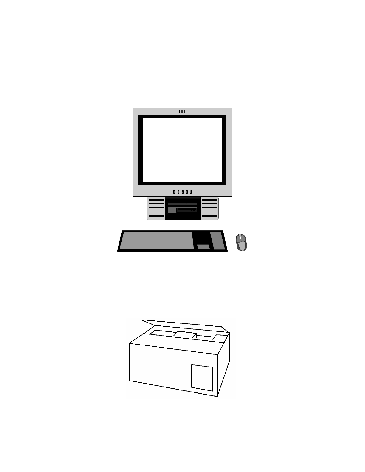
2. Setting up your Omnino HS
Detailed in this chapter is comprehensive information on how to unbox, assemble
and use your Omnino HS system. The basic system consists of three main
components, the input devices (keyboard/mouse), output devices (monitor/
speakers) and the main system unit (also called the base unit). Examples are shown
below.
It is best if you give yourself a lot of space, and then unpack each box. It’s easier to
set-up the computer when everything is in front of you. Please follow these illustrated
instructions.
Step 1: Unpacking your Omnino HS
Page 8

Omnino HS Quick Start Guide – Ver 1.0
8
There should be two boxes that form your Viglen PC - a ‘System Unit Box’ and
sometimes an ‘Accessories Box’. Carefully unpack these boxes, and remove the
contents.
Note: DO NOT rest the unit on its screen.
Please Note: It is important that you keep the packaging in case
you have to return the unit at a later date. The packaging has been
designed to give maximum protection to the system during
transportation. No other alternatives would give as much
protection. Viglen cannot be held responsible for any damage that
occurs during transport.
Step 2:
The unit can be lifted out and placed on your desk - depending on your personal
preferences. As long as there is easy access to an AC mains socket, position the
unit so that the rear is easily accessible. Place the Omnino HS, keyboard and mouse
on the desk to suit your requirements.
Step 3:
Connect the AC power supply cable to the back of the base unit.
Note: On the Omnino HS, there is no power outlet socket for Monitors. Due to
the monitor being built in there is no need to connect power to the monitor.
Omnino HS – Rear View
Page 9
Omnino HS Quick Start Guide – Ver 1.0
9
Step 4:
Located underneath the rear of the base unit is an 'I/O Panel'. This is where you
connect the peripheral devices that come with your Omnino HS. If your system has
an ‘on-board’ sound card, the audio ports will be accessible. If these ports are
covered, your system either has an 'add-in' sound card - or no audio available.
Note: On certain models, the ports maybe arranged differently. ALWAYS
match the cables with the colours specified.
Omnino HS - Rear I/O Shield
Step 5:
Connect the Mouse to the GREEN PS2 socket, and the Keyboard to the PURPLE
PS2 socket. If you have a printer, plug the printer parallel cable into the PURPLE
parallel socket. If you have a USB printer then plug the USB cable into any of the
available USB ports.
Omnino HS – I/O Panel
Page 10

Omnino HS Quick Start Guide – Ver 1.0
10
Step 6:
Plug the video signal cable into the BLUE VGA connector; this is located on the
Interface panel. Both options are shown below.
Omnino HS – I/O Panel
Step 7:
Your Omnino HS may have an audio card installed (optional). Connect the stereo
speaker cable to the socket labelled 'OUT' or marked with the following icon:
Or
Plug your microphone into the socket labelled 'MIC' or marked with the following
icon:
If your Omnino HS has an ‘on-board’ sound card, the audio ports will be located on
the ‘interface panel’. Connect the stereo speaker cable to the GREEN socket, and
plug your microphone into the PINK socket. Both options are shown below.
Omnino HS – I/O Panel
DO NOT switch on the Omnino HS until steps 1 to 7 have been completed.
Page 11
Omnino HS Quick Start Guide – Ver 1.0
11
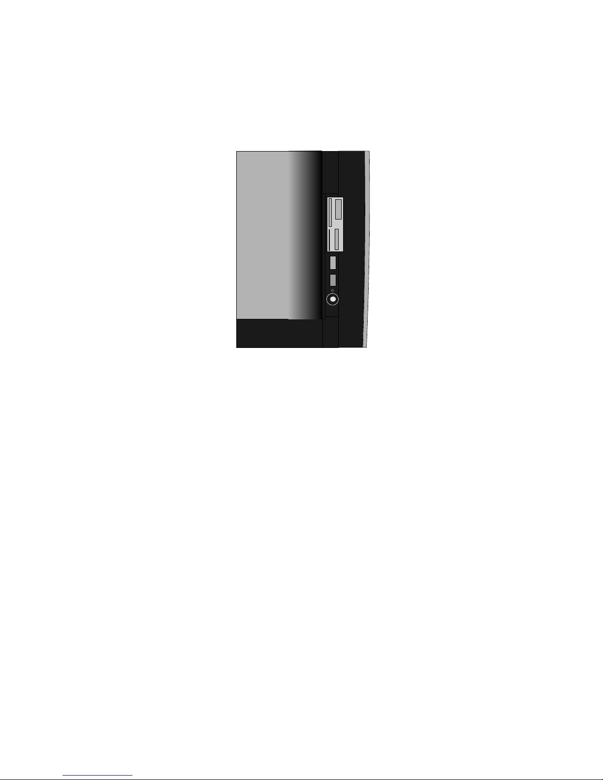
Step 8:
Plug the power cable into a standard mains socket, and switch on. Press the
monitor power button on the front of the case – a green or orange light should
appear under the button. Gently press the computer ON/OFF button, located on the
side of the system – as shown below.
You are now ready to explore the features of your new Omnino HS computer…
Enjoy!
NOTE: On most systems there is a ‘cold’ on/off switch on the back of the base
unit (next to the power socket). This switch physically disconnects the
computer from the power supply. If your Omnino HS is not switching on, try
checking that this switch is turned ‘on’.
Page 12

Omnino HS Quick Start Guide – Ver 1.0
12
3. Safety Precautions
Electrical Safety Precautions
• Basic electrical safety precautions should be followed to protect you from harm
and the Omnino HS from damage:
• Be aware of the locations of the power on/off switch on the chassis as well as the
room's emergency power-off switch, disconnection switch or electrical outlet. If an
electrical accident occurs, you can then quickly remove power from the system.
• Do not work alone when working with high voltage components.
• Power should always be disconnected from the system when removing or
installing main system components, such as the motherboard, memory modules
and the CD-ROM and floppy drives. When disconnecting power, you should first
power down the system with the operating system and then unplug the power
cords of all the power supply units in the system.
• When working around exposed electrical circuits, another person who is familiar
with the power-off controls should be nearby to switch off the power if necessary.
• Use only one hand when working with powered-on electrical equipment. This is to
avoid making a complete circuit, which will cause electrical shock. Use extreme
caution when using metal tools, which can easily damage any electrical
components or circuit boards they come into contact with.
• Do not use mats designed to decrease electrostatic discharge as protection from
electrical shock. Instead, use rubber mats that have been specifically designed
as electrical insulators.
• The power supply power cord must include a grounding plug and must be
plugged into grounded electrical outlets.
• Motherboard Battery: CAUTION
- There is a danger of explosion if the onboard
battery is installed upside down, which will reverse its polarities. On the Omnino
HS, the positive side should be facing up. This battery must be replaced only with
the same or an equivalent type recommended by the manufacturer. Dispose of
used batteries according to the manufacturer's instructions.
Page 13

Omnino HS Quick Start Guide – Ver 1.0
13
General Safety Precautions
Follow these rules to ensure general safety:
• Keep the area around the Omnino HS clean and free of clutter.
• Place the chassis top cover and any system components that have been
removed away from the system or on a table so that they won't accidentally be
stepped on.
• While working on the system, do not wear loose clothing such as neckties and
unbuttoned shirt sleeves, which can come into contact with electrical circuits or
be pulled into a cooling fan.
• Remove any jewelry or metal objects from your body, which are excellent metal
conductors that can create short circuits and harm you if they come into contact
with printed circuit boards or areas where power is present.
• After accessing the inside of the system, close the system back up and secure it
to the rack unit with the retention screws after ensuring that all connections have
been made.
ESD Precautions
Electrostatic discharge (ESD) is generated by two objects with different electrical
charges coming into contact with each other. An electrical discharge is created to
neutralise this difference, which can damage electronic components and printed
circuit boards. The following measures are generally sufficient to neutralise this
difference before contact is made to protect your equipment from ESD:
• Use a grounded wrist strap designed to prevent static discharge.
• Keep all components and printed circuit boards (PCBs) in their antistatic bags
until ready for use.
• Touch a grounded metal object before removing the board from the antistatic
bag.
• Do not let components or PCBs come into contact with your clothing, which may
retain a charge even if you are wearing a wrist strap.
• Handle a board by its edges only; do not touch its components, peripheral chips,
memory modules or contacts.
• When handling chips or modules, avoid touching their pins.
• Put the motherboard and peripherals back into their antistatic bags when not in
use.
Page 14

Omnino HS Quick Start Guide – Ver 1.0
14
• For grounding purposes, make sure your computer chassis provides excellent
conductivity between the power supply, the case, the mounting fasteners and the
motherboard.
Operating Precautions
Care must be taken to assure that the chassis cover is in place when the Omnino HS
is operating to assure proper cooling. Out of warranty damage to the Omnino HS
system can occur if this practice is not strictly followed.
Page 15

Omnino HS Quick Start Guide – Ver 1.0
15
4. General Description
This section gives a general description and overview of the various features of your
Omnino HS.
Various abbreviations will be used to describe the size of a computer’s storage
capacity. A unit of storage is known as a ‘byte’, or sometimes as an ‘octet’ - 1024
bytes is known as a ‘Kilobyte’ or ’KB’. Following on in this fashion, 1024KB is known
as a ‘Megabyte’ or ‘MB’, and 1024MB is known as a ‘Gigabyte’ or ‘GB’. Your
computer’s RAM will have in the region of 32MB to 256MB storage capacity, where
your hard disk will have anything from 3.4GB to 18GB storage or even higher!
SONY
Omnino HS – Front Control Panel
Page 16

Omnino HS Quick Start Guide – Ver 1.0
16
Front Control Panel
The functions of the various lights and switches are as follows:
Power light (green): When illuminated, this indicates that the system
is switched on.
Auto: Automatically adjusts the screen.
Left and Right arrow: Navigates though the on screen menus.
Menu: Accesses the on screen menu.
Power Switch: The power switch is used to turn the system On and
Off. The Omnino HS has an advanced power management system,
which includes an electronic power switch. With the advanced power
management system, the Operating System can turn the computer off
automatically if asked.
Page 17

Omnino HS Quick Start Guide – Ver 1.0
17
The Real Time Clock
Viglen PC’s are IBM AT compatible computers and hence the whole system
configuration is set up in battery-backed CMOS RAM. This information indicates the
type of hardware and memory configuration that the system includes. It is important
that this information is set up correctly; otherwise the computer may find errors and
may not be able to access the hardware correctly. The correct information is preset
for you; however, you can change this information if required by running the SETUP
utility. Refer to the motherboard manual for further details. The time and date
information is also stored in the battery-backed RAM. Thus, when the power is
switched off, the time and date is kept running and will be correctly set up the next
time that the computer is switched on again. The correct time and date is also
preset for you but can be changed if required by double clicking on the clock in the
lower right hand side of your Windows desktop.
Floppy and Hard Disk Drives
Your computer requires storage and memory devices in order to store programs and
data and any other information. This memory can be either volatile or non-volatile.
Information stored in volatile memory is lost when the power is switched off - but with
non-volatile memory, the information is retained.
The most important type of non-volatile memory is obtained by storing information on
magnetic media called disks or diskettes. System Information is also stored in
battery backed memory where a battery supplies power to maintain the information
when the mains power is turned off. The hardware units that are used to store
information on magnetic disks are called disk drives.
The two most common types of disk drives are Floppy Disk Drives and Hard Disk
Drives.
Floppy Disk Drives
Floppy Disk Drives enable the computer to read from, or write to, floppy disks that
are inserted into the drive. These disks can then be removed or taken to another
computer where they can also be used. The information is stored as a ‘magnetic
picture’, and held permanently on the disk until deletion of the data.
A 1.44MB drive can read and write both 720KB and 1.44MB format disks. If a 720KB
formatted disk is inserted the drive will automatically read and write in the 720KB
format. Likewise, if a 1.44MB formatted disk is inserted; the system will
automatically read and write in the 1.44MB format. The 3.5” FDD is the standard
drive for flexible data storage and transferral – you might buy some software that
comes on 3.5” floppy disk for instance.
Page 18

Omnino HS Quick Start Guide – Ver 1.0
18
SONY
Omnino HS – Floppy Disk Drive
NOTE: The correct type of disk must be used for the correct format. There is a
disk sensing unit on the drive which will not allow the wrong media type of
disk to be used. i.e. a 720K formatted disk must be a standard double-density
media and a 1.44M formatted disk must be a high-density media.
If the write-protect hole is "OPEN" (I.e. you can see through it), it indicates that the
disk is write protected. In this state, you will be unable to change the contents of the
disk. If you close the hole (by sliding the plastic insert across), the disk is NOT writeprotected. In this state, you can write to, and delete information from the disk.
Hard Disk Drives
A hard disk operates in a similar way to a floppy disk with one major difference. The
disks used to store the information are sealed inside the mechanism and cannot be
removed. Because the unit is sealed, more than one disk can be included and the
data on these disks can be packed in a far greater density.
Today, hard disk storage capacity is measured in ‘GB’ (Gigabytes). One GB is
equivalent to:
1,073,741,824 characters of information, or ‘bytes’…
If a book had 80 characters on each line, 40 lines of text on each page and 300
pages – you’d be able to fit all the information in the book onto a 3.4GB hard disk –
not once, but over 3,803 times!!
It is advised to keep your hard disk ‘clean’ (in a data sense rather than a physical
sense!). If you are not going to use a certain application ever again, uninstall it rather
than just leaving it on your hard disk. For information about uninstalling an
application, please refer to the accompanying documentation.
CD-ROM, CD-R/W, DVD-ROM, DVD-RAM Drives
Your Omnino HS has been supplied with either a high speed (52x or above) CDROM, or a DVD-ROM drive, according on which model you purchased. CD-ROM’s
and DVD-ROM’s are both medium speed, non-volatile mass storage devices. The
large storage capacity and cheap manufacturing has made the CD the ideal medium
for multimedia and the distribution of large program suites such as Operating
Systems. DVD disks are very similar CD-ROM’s, but their storage capacity is much
greater.
Page 19

Omnino HS Quick Start Guide – Ver 1.0
19
CD-ROM Drive
The CD-ROM drive in your machine has the capability to spin CD's at up to thirty two
(or higher) times the original specification for CD ROM drives. This allows it to read
the information from the surface of the CD at a very high speed, stopping the CPU
from waiting for the next piece of information. Your drive has already been
configured for your system and is ready to use after booting the computer. Your CDROM will take the first drive letter available after the last Hard Drive. In most cases
this will be D:
CD-R/RW Drive
A CD-R/RW drive works in much the same way as a standard CD-ROM drive except
that it has the capability to write to blank CD-R or CD-RW media. A CD-R disc can
only be written to once where as a CD-RW disc can be written to and erased many
times.
DVD-ROM Drive
DVD stands for ‘Digital Versatile Disk’, and is the successor to the standard CDROM technology. DVD drives have the ability to access over 17GB of information on
a single DVD disk, while maintaining backwards compatibility with standard CDROM’s. DVD was primarily pioneered for the film industry – its massive storage
means it’s possible to place a blockbuster film on just one disk. In fact, you can also
have the film in many different languages as well.
The DVD drive uses dual-focus laser technology, and is one of the most advanced
pieces of CD based technology there is.
DVD-RAM Drive
The DVD-RAM drive has the same capabilities as a DVD-ROM drive with the
additional benefit of being able to write to blank DVD-R media.
Page 20
Omnino HS Quick Start Guide – Ver 1.0
20
Inserting/Removing a CD:
1) To Insert a CD into your CD-ROM/DVD drive simply press the Eject button on the
front of the drive. This will cause the CD-ROM/DVD drive to eject the CD tray,
after the drive has been ejected pull the tray the rest of the way.
2) Place the CD in the centre of the tray and ensure it is sitting in the spindle of the
CD-ROM drive.
3) Press the Eject button once more and the tray will retreat back into the machine
with the CD in the tray.
4) The CD is now loaded and will be automatically read to ascertain a label name
and other details.
5) The CD is now accessible from the D: drive.
To remove a CD repeat the above steps 1-3 removing the CD at step 2.
If you insert an audio CD into your drive, your computer will automatically start to
play the first track on the CD.
System Memory
Your Omnino HS will use some of the latest memory technology available at the
time. The system memory is volatile memory and is used by the computer as
storage whilst it is operating. All the information held in this memory is lost when the
power is switched off.
To identify the amount of RAM supplied in the system (typically 128MB to 2GB).
You must make sure that there is enough memory to run your required program.
The amount of memory required is normally indicated on the software package.
Cache RAM is the fastest type of RAM you can get (and the most expensive). It sits
in-between the processor and the main system memory, and stores data that is
repeatedly required by the CPU.
A typical system has 512KB of Cache RAM – or 128KB cache if a Celeron processor
is installed.
Page 21

Omnino HS Quick Start Guide – Ver 1.0
21
I/O Ports and the Interface Panel
The communication between your Omnino HS and other devices is performed via
I/O (Input/Output) interfaces or ‘ports’. You will probably never use all the ports on
the back of your computer, but a wide selection is available for maximum flexibility.
All of the industry standard ports are available, and they are individually coloured
and labelled with icons for simple installation of peripherals.
This section of the manual will explain the different uses of each port, and a little on
the peripheral types.
Most of the I/O ports on the back of your Omnino HS have been conveniently
grouped into one area. This region of the PC is known as the ‘Interface Panel’.
Omnino HS - Interface Panel
Note: Your system may be configured slightly differently to the diagram above.
The Games, Speaker, Line-in and Mic-in ports maybe on a separate add-in card
– or you may not have audio at all in your configuration. On some systems, the
second serial port is actually the VGA port instead (to connect the PC to the
monitor). Please ensure you understand the configuration of your Viglen
system before attempting to install it.
Your Interface Panel may have a slightly different layout to the diagram above.
Always use the colours and symbols to locate the correct I/O ports.
Page 22
Omnino HS Quick Start Guide – Ver 1.0
22
I/O Port descriptions:
PS/2 port (mouse) (Green)
The PS/2 port is the industry standard for connecting a mouse to a PC.
Before inserting the cable into the socket, ensure you have lined the pins
up. There is only one way the cable can be inserted, so if it’s not going in
– do not use excessive pressure!
PS/2 port (Keyboard) (Purple)
The PS/2 port is also the industry standard for connecting a keyboard to a
PC. Before inserting the cable into the socket, ensure you have lined the
pins up. There is only one way the cable can be inserted, so if it’s not
going in – do not use excessive pressure!
USB port (Black)
USB stands for Universal Serial Bus, and has been designed into your
system to ensure full compatibility with future peripheral technologies.
Most devices in the future such as keyboards, scanners, joysticks and
speakers will come with a USB port attached. It has been designed with
ease of use in mind – allowing you to plug in a USB peripheral and use it
without restarting your computer. There are two USB ports on your
system.
Parallel port (Burgundy / Red)
The parallel port is also known as a Centronics port (named after the
company that originated the standard), and is used mainly to connect
printers or scanners to your computer.
Serial port (Turquoise)
The serial port uses the international RS232C (or updated) standard to
provide serial asynchronous communication. It can be used to connect
external serial devices such as a modem, mouse etc. A printer with a
serial port can also be connected to this port. On some systems, the
rightmost serial port has been replaced by a VGA port.
VGA port (Dark Blue)
The VGA port is the main interface between the base unit and the
monitor. A thick 15-pin monitor cable is usually used to link the two units
together. The VGA port will usually be found on an add-in card rather than
the Interface Panel. On some systems, the rightmost serial port has been
replaced by the VGA port to save space for more add-in cards.
Page 23

Omnino HS Quick Start Guide – Ver 1.0
23
Games port (Gold) - optional
The game port is used to connect an IBM compatible analogue joystick. It
also doubles up as a MIDI (Musical Instrument Digital Interface) port for
playing or recording music (with the correct cable attached). This port has
a 15-pin socket, and will either be located on the I/O panel or on an add-in
card.
Line in (Light Blue) - optional
‘Line in’ can be used if you wanted to digitally record an audio source. It
accepts a standard 3.5mm audio jack, and records in stereo. If you are
using a microphone to record audio, it’s advisable to use the ‘Mic in’
instead of the ‘Line in’. If installed, this port will either be located on the I/O
panel or on an add-in card.
Mic in (Pink) - optional
‘Mic in’ can be used to record your voice via an external Microphone. The
record level of the microphone can be adjusted via software. The ‘Mic in’
port includes a small amplifier, and If you are recording from a powered
source (Hi-Fi etc) it’s suggested you use the ‘Line in’ for better sound
quality. If installed, this port will either be located on the I/O panel or on an
add-in card.
Speakers (Green) – optional
Connect your speakers or headphones to this stereo socket. Ensure the
volume is turned down before connecting speakers to this port. If installed,
this port will either be located on the I/O panel or on an add-in card.
USB Ports
USB is an abbreviation of Universal Serial Bus. USB is a standard port that enables
you to connect external devices (such as digital cameras, scanners, mice,
keyboards, modems) to PC’s. It is a standard designed to eliminate the guesswork
in connecting peripherals to your PC.
USB replaces all the different kinds of serial and parallel port connectors with one
standardised plug and port combination (see image below).
USB Plug
Page 24
Omnino HS Quick Start Guide – Ver 1.0
24
With USB-compliant PC’s and peripherals, you just plug them in and turn them on!
USB makes the whole process automatic.
Thanks to another USB feature known as ‘hot-swapping’ you don’t even need to shut
down and restart your PC to attach or remove a peripheral.
USB Standards
Currently there are two versions of the USB standard that have been developed by
the USB Implementers forum.
IEEE1394 Firewire
Also known as Apple’s FireWire™ and Sony’s i-Link is an industry standard for a
scalable, flexible, easy to use, low cost digital interface that integrates the world of
consumer electronics and personal computers.
1394 is a digital standard and does not require the conversion of digital data into
analogue, which means better signal integrity. It supports guaranteed delivery of
time critical data which enables high-quality audio and video applications.
USB 1.1 (1995) defines two speeds 12Mbps (full
speed) and 1.5Mbps (low speed) and two types
of connectors: Series A and Series B.
USB 2.0 (2000) defines three speeds 480Mbps
(high speed), 12Mbps and 1.5Mbps (full speed)
and 1.5Mbps (low speed). It is completely
backwards compatible with USB 1.1.
Page 25
Omnino HS Quick Start Guide – Ver 1.0
25
The IEEE1394 interface has been designed to be physically small and easy to use.
Devices can be added and removed without requiring the PC to be rebooted
(IEEE1394 supports hot-swapping).
IEEE1394 Standards
There are two IEEE1394 standards currently available. Standard (a) supports
transfer rates up to 400Mbps and standard (b) supports up to 800Mbps.
Shown below are example images of the two different IEEE1394 ports and the
different interface cables used:
Standard 6-pin port Standard 4-pin port
6-6 pin cable 4-4 pin cable 4-6 pin cable
Serial ATA
A disk-interface technology developed to replace parallel ATA. When most people
think "serial", they tend to think of the serial ports found on the rear I/O of a PC.
These asynchronous serial ports are very slow but synchronous serial offers greatly
improved data throughput. A typical asynchronous serial port is capable of 115kb/s
but a serial ATA port (synchronous serial port) can support a throughput of more
than 1,000,000kb/s.
S-ATA not only offers faster transfer rates but also a better cabling solution
compared to the older P-ATA (Parallel-ATA) 40-pin standard (see below):
Page 26
Omnino HS Quick Start Guide – Ver 1.0
26
Parallel ATA (grey cable) Vs Serial ATA (red cable)
AGP (Advanced Graphics Port)
AGP is a high performance interconnect between the chipset and graphics controller
for enhanced 3D graphics performance. AGP relieves the graphics bottleneck by
adding a dedicated high-speed interface directly between the chipset and the
graphics controller as shown below:
AGP Standards
There are two specifications that define AGP. The AGP Specification revision 2.0
defines an interface supporting 1x and 2x speeds at 3.3V and 1x, 2x, and 4x speeds
at 1.5V signalling. The AGP3.0 specification defines a new signalling scheme for 4x
and 8x speeds at .8V signalling levels.
Page 27

Omnino HS Quick Start Guide – Ver 1.0
27
Connecting your Monitor
1) Turn off the power of your computer and other devices.
2) Connect the video signal cable of the monitor to the 15-pin VGA connector on the
back of your computer. The VGA port will either be on the Interface Panel, or
mounted on an add-in card. The port is labelled with the following icon:
3) Turn on the computer.
4) If necessary, adjust the front panel controls accordingly to your personal
preference.
Page 28

Omnino HS Quick Start Guide – Ver 1.0
28
5. Optional Features
This chapter explains some of the optional features you may have ordered with your
Omnino HS. If you have a basic configuration, then you can skip this section of the
manual.
Your Omnino HS has been engineered to give you a powerful yet manageable
computing experience. You have the option to upgrade your Omnino HS, or add a
component whenever you require. So if you don’t have audio now - it doesn’t mean
you can never have it. Just contact the Viglen Service department for a catalogue of
upgrades for your system.
Audio ports
The audio ports connect your computer to external devices such as a microphone or
a set of speakers. If you have purchased audio with your Viglen Omnino HS, there
will either be a set of speakers supplied with the computer or built into the monitor.
The audio ports on your Omnino HS will either be located on the Interface Panel, or
on a separate add-in card. Either way, the internationally accepted port icons will be
the same:
SPEAKERS LINE-IN MICROPHONE
If your Omnino HS has external speakers supplied, there will be a separate
instruction sheet supplied with the speakers describing the installation. Please read
this sheet before continuing.
Generally, the external speaker system will consist of two separate units to
reproduce a stereo signal. If you have selected a high power unit, you will probably
receive three speakers… left, right, and a subwoofer.
However these speakers are attached to each other, there will always only be one
cable to connect the speakers to the PC. This will take the form of a stereo 3.5mm
jack:
Page 29

Omnino HS Quick Start Guide – Ver 1.0
29
Omnino HS - A stereo 3.5mm Jack
You must plug this jack into the ‘Speaker’ port on the computer.
The speaker port on your computer will be labelled with one of the following
international symbols:
The volume of your speakers can either be controlled by software, or by the volume
controls on your speakers (see the supplied documentation for further information).
WARNING: Ensure your speaker system volume is turned down before you
connect the speakers.
Graphics Card
If a separate graphics card has been supplied with your system, this section will look
at the best way to set it up. It is possible you have one of a number of I/O options on
the ‘back plates’ of your graphics card - this section will explain how to set up each
variant.
Diagram Keys:
Or
VGA Connector
TV-Out Connector
DVI Connector
Page 30

Omnino HS Quick Start Guide – Ver 1.0
30
VARIENT 1 - Standard VGA Card
VARIENT 2 - Standard VGA Card + TV Out
Variant 1 shows a typical example of a
VGA card. The monitor connector cable
will only fit one way and can normally be
screwed into the graphics card itself.
Variant 2 shows a typical example of a
VGA card with TV Out. The monitor
connector cable will only fit one way and
can normally be screwed into the graphics
card itself. The TV/Composite video cable
plugs straight into the TV Out socket.
Page 31

Omnino HS Quick Start Guide – Ver 1.0
31
Modem
If a modem has been supplied with your system, this section will look at the best way
to set it up and connect your computer to the outside world. It is possible you have
one of a number of ‘back plates’ on your modem - this section will explain how to set
up each of the variants.
VARIENT 1:
This modem may or may not have
voice capabilities. Please consult the
Supplied documentation for further
information.
VARIENT 2:
LINE
Connect to
your phone
socket.
LINE
Connect to
your phone
socket.
Your modem has a ’line’ and a
‘phone’ socket - both are labelled.
Connect the cable supplied to the
socket labelled ‘line’. The other
socket can be used to install a phone
if you desire.
Page 32

Omnino HS Quick Start Guide – Ver 1.0
32
6. Troubleshooting
What to do if the system doesn’t work
This section describes basic problems and the remedies that can be used if the
system does not seem to work correctly. Most problems can be sorted out very
quickly once the root cause is established.
Before seeking assistance, have a look at these common problems and their
possible solutions.
Try, wherever possible to isolate the problem by trying out a replacement device (i.e.
mouse, keyboard etc.) if one is at hand. This will help you identify the item that is
causing the problem and make it easier for the problem to be efficiently dealt with.
Note: Please don’t remove the system unit cover: This action should only be
performed by a qualified engineer, as you risk injury by hazardous voltages.
Problem Action
Check AC mains cable is plugged firmly in the back of the main system unit.
Check power On/Off switch is in the ON position.
No Power.
No Lights on
Front of the
main system
unit
Check the fuse in mains plug. If it has blown, replace it with one of the same
rating. If the fuse blows persistently, then unplug the power cable to the monitor
and try again.
Problem Action
Check the power light on the monitor. If this is not lit, then check that the monitor
power ON/OFF switch is in the ON position. Check that the AC power lead at the
rear of the monitor is plugged firmly into the monitor and the power outlet at the
rear of the main system unit.
Main system
unit is OK, but
no display or
incorrect
display on
monitor
If the power light on the monitor is lit and the screen is blank, then test the
following:
a) Turn the contrast and brightness controls on the monitor in case they have
been set to dark.
b) Check that the signal cable at the back of the monitor is plugged into the
socket labelled VGA or at the rear of the main system unit.
c) If some of the colours are missing, check that the pins on the signal cable are
not bent.
d) Check that the video display card is correctly seated in the expansion slot.
Page 33
Omnino HS Quick Start Guide – Ver 1.0
33
Problem Action
Check the power light on the monitor. If this is not lit, then check that the monitor
power ON/OFF switch is in the ON position. Check that the AC power lead at the
rear of the monitor is plugged firmly into the monitor and the power outlet at the
rear of the main system unit.
Main system
unit is OK, but
no display or
incorrect
display on
monitor
If the power light on the monitor is lit and the screen is blank, then test the
following:
e) Turn the contrast and brightness controls on the monitor in case they have
been set to dark.
f) Check that the signal cable at the back of the monitor is plugged into the
socket labelled VGA or at the rear of the main system unit.
g) If some of the colours are missing, check that the pins on the signal cable are
not bent.
h) Check that the video display card is correctly seated in the expansion slot.
Problem Action
If the hard disk cannot be accessed at all, then check the following:
a) Check that the correct hard disk type is entered in the CMOS RAM by
entering the SETUP routine. Refer to the System manual for further
information.
b) Check that the leads to the hard disk and from the IDE controller are plugged
in fully
Try to boot from the floppy drive in drive A: by placing the Windows start-up disk
in drive A and resetting the system. Once your computer has booted up, you
should then try to access the hard disk by entering C: This is done by entering:
C:, now try entering DIR
Unit does not
boot from hard
disk drive C:
If the hard disk can be accessed through MS-DOS (if performing the above point
did not return an error), but will not boot normally - the system files have been
damaged. Back up all of your data, and reinstall you operating system from
scratch.
Problem Action
Check that the correct type of floppy disk is being used. Remember a 1.44MB
Floppy Disk Drive will not read LS-120 disks.
Try another disk…Sometimes floppy disks may get dust or scratched on the
surfaces, damaging them.
Floppy disk
drive does not
read or write
Check in the CMOS SETUP routine that the correct type of drive has been
selected. (Refer to your System manual).
Page 34

Omnino HS Quick Start Guide – Ver 1.0
34
Problem Action
No input from
the keyboard
Check that the keyboard plug is firmly inserted into the socket labelled ‘keyboard’
at the rear of the main system unit. If the ‘Caps Lock’ LED lights up when
pressed, there is an electrical connection.
Problem Action
The mouse is
not being
recognised.
The mouse is not plugged in correctly.
Solution: Check mouse plug - make sure the plug is inserted in the correct port.
The plug may become loose after prolonged use.
Page 35

Omnino HS Quick Start Guide – Ver 1.0
35
7. Glossary
This section gives a brief description of the most commonly used computer terms.
A Ampere, This is a term of measurement for electric
Current.
AC Alternating Current used to describe the mains voltage.
Ampere This is a term of measurement of electric current.
Analog Pertaining to data in the form of continuously variable
quantities. Contrasts with Digital.
ANSI American National Standards Institute.
ASCHS American Standard Coded for Information
Interchange.
This is a special 7/8 bit code that is given to identify
characters.
Asynchronous a Method of transmission of data in which the bits
included in a character or block of characters occur
during a specific time interval. The start of each character
block can occur at any time during this interval.
Contrasts with synchronous.
AUTOEXEC.BAT A special batch file, which contains a series of commands
that are to be executed when the computer is started up.
BASIC Beginner’s All-purpose Symbolic Instruction Code. This
is a simple programming language.
Battery-Backed RAM A type of memory that holds information even when the
computer is switched off.
Baud A term used to measure modem data rates.
Binary Involving a choice of two conditions, such as "yes" or
"no", "1" or "0", base-2 mathematics.
BIOS Basic Input Output System. This is the program held in
the computer's ROM which handles all the input and
output functions.
Bit Synonym for Binary digit. A single unit of information
which can hold a value of 0 or 1.
Page 36

Omnino HS Quick Start Guide – Ver 1.0
36
Boot The name given to the program that runs on the
computer when it is first switched on. Can also be a verb
related to running the program.
BSI British Standards Institute.
Bps Bits per second.
Buffer An area of temporary storage.
Bus One or more conductors used for transmitting signals.
Byte A unit of data made up of eight Bits.
C / C++ A programming language.
Cache A small area of high-speed memory.
Cathode Ray Normally referred to as a monitor or VDU.
Tube (CRT)
Character A symbol on the screen or same as a Byte.
CMOS Complementary Metal Oxide Semiconductor. A logic
circuit family that uses very little power.
COM1, COM2 The names given to the serial communications ports in
COM3, COM4 DOS.
CONFIG.SYS A special purpose file which has the configuration details
for the computer to set itself to when powered up.
CPS Characters per second.
CSA Canadian Standards Association.
Cursor A bar on the screen that indicates where the input from
the keyboard will be displayed.
DC Direct current. Normally associated with battery current.
Digital Pertaining to data in the form of binary digits. Contrasts
with Analogue.
DIN Deutsche Industrie Norm specifies major connector
types.
DIP Dual In-Line Package. ICs that have two parallel rows of
connections.
Page 37

Omnino HS Quick Start Guide – Ver 1.0
37
DMA Direct Memory Access. A method of transferring data
between main storage and I/O devices without processor
intervention.
Disk See Floppy Disk.
DOS or MS-DOS® Disk Operating System or Microsoft Disk Operating
System. This is a low-level program that instructs the
computer on basic file handling.#
DRAM Dynamic RAM. A type of RAM that requires a periodic
refresh to maintain data.
DVD Digital Versatile Disk
EMC Electromagnetic Compatibility
EMI Electromagnetic Interference.
EPROM Erasable Programmable Read-Only Memory.
ESDI Enhanced Small Device Interface, which specifies a fast
hard disk interface.
FCC Federal Communications Commission.
Firmware A program that is resident in Read Only Memory (ROM).
Floppy Disk A storage device consisting of a flexible magnetic disk
inside a protective cover.
G A symbol used to represent the prefix Giga. i.e. GB (Giga
Byte).
GB Gigabyte, represents 1,073,741,824 bytes (1024MB).
Hard Disk A disk of rigid magnetic material used for mass storage.
Hardware The physical equipment which makes up the computer
system.
Hertz (Hz) A unit of measurement of frequency amounting to one
cycle per second.
Hex Hexadecimal. Base-16 mathematics.
IC Integrated Circuit.
Icon A graphical symbol.
Page 38

Omnino HS Quick Start Guide – Ver 1.0
38
IDE Integrated device interface. An AT bus specification for a
fast hard disk.
IEC International Electrotechnical Commission. Specifies
standards of safety.
I/O Input/Output. Refers to data being sent to or received
from a computer.
K Symbol used to represent Kilobyte which is 1024 bytes.
KB Abbreviation for Kilobyte, i.e. 1024 bytes.
Kb Abbreviation for Kilo bit, i.e. 1024 bits.
Keylock A locking device which can deactivate a keyboard.
KHz KiloHertz. 1000 Hertz.
LIM Lotus/Intel/ Microsoft Expanded Memory Manager
specification.
LED Light Emitting Diode. These are normally used as the
lights on a computers front panel.
LPT1, LPT2, LPT3 Names given to the printer ports by DOS.
M Prefix mega. Equivalent to 1024K.
mA Milliampere. 0.001 Ampere.
MB Abbreviation for Mega Byte i.e. 1024K Bytes.
Mb Abbreviation for Mega Bits, i.e. 1024K bits.
Memory An electronic component, which remembers data, stored
in it.
MHz Mega Hertz. 1,000,000 Hertz.
ns Nano Second 0.000 000 001 second.
Pixel The smallest displayable unit on a monitor or picture
tube.
POST Power-On Self Test.
RAM Random Access Memory. Fast Read/Write memory.
RFI Radio Frequency Interface.
Page 39

Omnino HS Quick Start Guide – Ver 1.0
39
ROM Read Only Memory.
RS-232C A standard for asynchronous serial communication.
SCSI Small Computer Systems Interface. A multimedia bus
and interface specification for fast Hard Disks, Tape
Backup Units, CD ROMs and other Devices.
SIMM Single In-Line Memory Module.
Software Another name for a computer program.
SRAM Static RAM. Synchronous Transmission of data between
devices which are maintaining the same frequency
relationship. Contrasts with asynchronous.
TPI Tracks Per Inch.
TTL Transistor Transistor Logic.
TUV Technischer Uberwachungs-Verein. Organisation which
tests and certifies electronic equipment.
UL Underwriter Laboratories. American Organisation
specifying standards for safety of electronic equipment.
USB Universal Serial Bus
V Volt. Unit of measurement of potential difference.
VAC Volts (Alternating Current).
VDE Verband Deutscher Electrotechniker. German
organisation specifying EMI suppression.
Video Computer data or graphics displayed on a monitor or
screen.
W Watt.
Watt Basic unit of measurement of electrical power.
Page 40

Omnino HS Quick Start Guide – Ver 1.0
40
8. Notes
Page 41

Omnino HS Quick Start Guide – Ver 1.0
41
Page 42

Omnino HS Quick Start Guide – Ver 1.0
42
Page 43

Omnino HS Quick Start Guide – Ver 1.0
43
Page 44

Omnino HS Quick Start Guide – Ver 1.0
44
9. Suggestions
Viglen is interested in continuing to improve the quality and information provided in
their manuals. Viglen has listed some questions that you may like to answer and
return to Viglen. This will help Viglen help to keep and improve the standard of their
manuals.
1. Is the information provided in this and other manuals clear enough?
2. What could be added to the manual to improve it?
3. Does the manual go into enough detail?
4. Would you like an on-line version of this manual?
5. How do you rate the Viglen Technical support and Service Departments?
Page 45

Omnino HS Quick Start Guide – Ver 1.0
45
6. Are there any technological improvements that could be made to the system?
1. Other points you would like to mention?
Please return this slip to: Product Development Department
Viglen Ltd
Viglen House
Alperton Lane
Alperton
Middlesex
HA0 1DX
 Loading...