

VIGILEC mini V1N, Vigilec mono V1M Installation And Operation Manual
INSTALLATION AND OPERATION
Pump controller and protection for one pump
Multicontrol
+info: www.vigilec.com
Mod. Vigilec mini
(V1N)
Mod. Vigilec mono
(V1M)
Page 2
ITM-0060-0069-ED3
Main features
Common applications
An all-in-one control and protection unit for any •
pump.
Multicontrol.•
Vigilec mini: Three-phase. 230/400 V~. Direct-•
on-line starting (DOL).
Vigilec mono: Single-phase 230V~. Direct-on-•
line starting (DOL).
Protection against connection failure to the •
pump.
Protection against overvoltage.•
Protection against overload.•
Protection against underload.•
Protection against phase failure (Vigilec mini).•
Stormproof.•
Protection against dry running with 3 possible •
confi gurations:
1) TWO PROBES: low and high level.
2) ONE PROBE: low level only.
3) Underload: WITHOUT PROBES
In case 2 and 3, restarting after 15 min.
Adjustable OVERLOAD and UNDERLOAD •
electronic relays. Alarm trip in 7 s. (overload)
or in 4 s. (underload).
Protection against pump jamming during long •
rest periods (only in AUTO mode).
Guaranteed against incorrect connections.•
Remote control output admitting 6 to 400 V~/•
V= contact or voltage.
All control devices in low voltage.•
Selection MAN-0-AUT by push-buttons.•
MAIN SUPPLY led, PUMP RUNNING led, •
WATER LEVEL ALARM led, OVERLOAD and
UNDERLOAD leds.
Reset push-button.•
General alarm output relay.•
Wide diameters range and high protection •
cable glands.
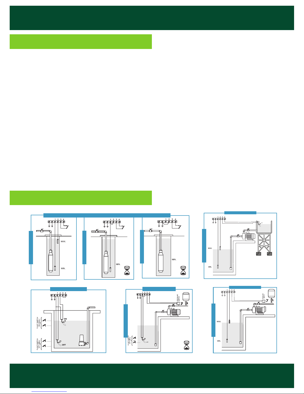
DRAINAGE & SEWAGE
BOOSTER SETS
PROBES MODE
WELL & TANK
PROBES MODE
2 PROBES MODE
ON
OFF
ON
OFF
BOOSTER SETS
FLOAT MODE
WITHOUT PROBES MODE
ON
DELAY
OFF (Amp)
ON
DELAY
OFF
1 PROBE MODE
WELL & BOREHOLE
ON
DELAY
OFF
Page 3
ITM-0060-0069-ED3
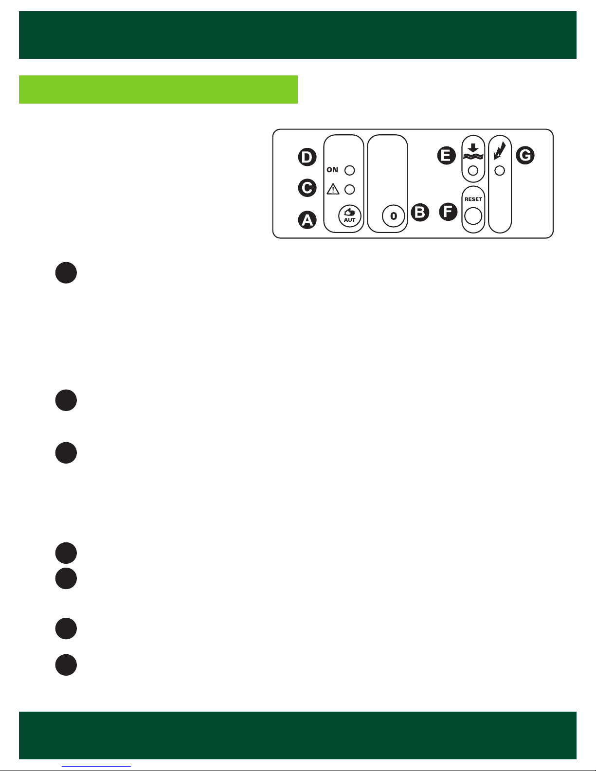
START button:
AUTOMATIC mode (green circle Led ON): press the button and the unit will work
automatically with the established controls and protections.
MANUAL mode (green circle Led fl ashing): holding down the button more than 4
seconds, the pump is forced to start running. The overload and underload motor
protections are on in this mode. By releasing the button, the pump stops immediately and the device goes back to the AUTOMATIC mode.
STOP (“0”) button: the unit stops the motor and blocks the re-start. If voltage failure
occurs, the established operation mode remains memorized, continuing in the same
mode (STOP-AUTO) once the voltage is restored.
Red Led: MOTOR ALARM.
Led fl ashing: re-start time after detection of motor alarm (overload: 7 seconds, •
underload: 4 seconds).
Led on: OVERLOAD ALARM.•
Led on fl ashing each 5 seconds: UNDERLOAD ALARM. •
Green Led: MOTOR RUNNING .
Orange Led: LOW LEVEL. Orange on: lack of water (2 probes mode). ORANGE
FLASHING: re-start time of 15 minutes after a lack of water (1 probe with delayed start
or without probes mode).
RESET button: Re-starts the unit after an alarm for OVERLOAD or UNDERLOAD or
stops the LACK OF WATER time delaying.
SUPPLY VOLTAGE Green Led: it lights when there is a supply voltage.
A
B
C
D
E
F
G
Front confi guration
Page 4
ITM-0060-0069-ED3
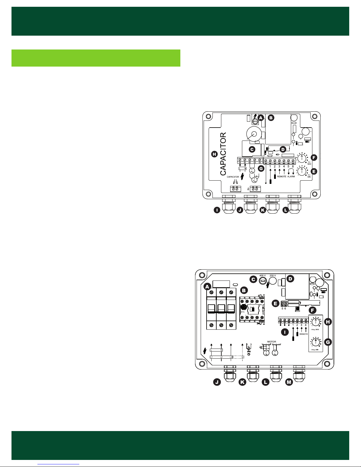
Internal confi guration
Control fuse (0,1A).A
Current transformer.B
Power relay.C
Flat cable connector.D
Minimum current adjustment (Amp. min).E
Maximum current adjustment (Amp. max).F
Control terminal blocks.G
Capacitor housing (submersible pumps).H
Main supply cable gland.I
Motor cable gland.J
Probes and earth cable gland.K
Remote / external alarm cable gland.L
Mod. Vigilec mini
Mod. Vigilec mono
Circuit breaker.A
Running motor contactor.B
Control fuses and voltage selection (0,1 A).C
Current transformer.D
General alarm output relay.E
Flat cable connector.F
Underload adjustment (Amp. min).G
Overload adjustment (Amp. max).H
Control terminal blocks.I
Main supply cable gland.J
Motor cable gland.K
Probes and earth cable gland.L
Remote /external alarm cable gland.M
 Loading...