

Vigilantplant RAGN User Manual
User´s
Manual
Model RAGN
Glass ROTAMETER
IM 01R01B10-00E-E
Rota Yokogawa GmbH & Co. KG
Rheinstr. 8
D-79664 Wehr
Germany
IM 01R01B10-00E-E
©Copyright 2011 (RYG)
4th edition: July 2017 (RYG

Blank Page

<CONTENTS>
i
IM 01R01B10-00E-E 4th edition: June 28, 2017-00
All Rights Reserved. Copyright © 2011, Rota Yokogawa
Contents
1. Introduction ......................................................................................... 1-1
1.1 ATEX Documentation ......................................................................................1-3
1.2 General description .........................................................................................1-4
1.3 Principle of measurement .............................................................................. 1-4
1.4 Intended use ....................................................................................................1- 4
2. Transportation and Storage ..............................................................2-1
3. Product description ...........................................................................3-1
3.1 Metering Tube ..................................................................................................3-1
3.2 Bistable inductive ring sensor (Option /GR2 to /GR8) ...............................3-2
3.3 Magnetic contact (Option /GM1 to /GM5) .....................................................3-2
3.4 Marking ............................................................................................................3-3
4. Installation ...........................................................................................4-1
4.1 General .............................................................................................................4-1
4.2 Piping ...............................................................................................................4-2
4.3 Bistable inductive ring sensor (Option /GR2 to /GR8) ...............................4-3
4.4 Magnetic contact (Option /GM1 to /GM5) .....................................................4-4
4.5 Connection box (Option /GD1 or /GD2) ........................................................4-5
5. Service ................................................................................................5-1
5.1 Customer maintenance part list (CMPL) ......................................................5-1
5.2 Template for sending back to service ..........................................................5-4
6. Explosion protected type instruments ............................................6-1
6.1 Bistable inductive ring sensor (Option /GR2 to /GR8) ...............................6-1
6.1.1 ATEX (option /KS1) ................................................................................................ 6-1
6.1.2 IECEx (option /ES1) ............................................................................................... 6-3
6.1.3 NEPSI (option /NS1) .............................................................................................. 6-3
6.1.4 Intrinsically safe
RAGN with option /GR2 ... /GR8 with Taiwan Safety Label
..... 6-3
6.2 Magnetic contact (Option /GM1 to /GM5) .....................................................6-4

<Contents>
ii
IM 01R01B10-00E-E 4th edition: June 28, 2017-00
All Rights Reserved. Copyright © 2011, Rota Yokogawa
7. Instructions for PED ........................................................................... 7-1
8. Technical Data ....................................................................................8-1
APPENDIX 1. Safety Instrumented Systems Installation .................. A1-1
A1.1 Scope and Purpose ................................................................................... A1-1
A1.2 Using RAGN for a SIS Application ........................................................... A1-1
A1.2.1 Safety Function ................................................................................................. A1-1
A1.2.2 Diagnostic Response Time .............................................................................. A1-2
A1.2.3 Setup .................................................................................................................. A1-2
A1.2.4 Proof Testing ..................................................................................................... A1-2
A1.2.5 Repair and replacement ................................................................................... A1-2
A1.2.6 Startup Time ...................................................................................................... A1-3
A1.2.7 Reliability data ..................................................................................................A1-3
A1.2.8 Lifetime limits .................................................................................................A1-3
A1.2.9 Environmental limits .........................................................................................A1-3
A1.2.10 Application limits ............................................................................................ A1-3
A1.3 Denitions and Abbreviations ................................................................... A1-4
A1.3.1 Denitions .........................................................................................................A1-4
A1.3.2 Abbreviations ....................................................................................................A1-4
A1.4 Assessment results .................................................................................... A1-5
A1.4.1 Safety related parameters ................................................................................ A1-5
< 1. INTRODUCTION>
1-1
IM 01R01B10-00E-E 4th edition: June 28, 2017-00
All Rights Reserved. Copyright © 2011, Rota Yokogawa
1. Introduction
Before use, read this manual thoroughly and
familiarize yourself fully with the features,
operations and handling of Rotameter RAGN to
have the instrument deliver its full capabilities and
to ensure its efficient and correct use.
Notices Regarding This Manual
• This manual should be passed to the end user.
• The contents of this manual are subject to
change without prior notice.
• All rights reserved. No part of this document
may be reproduced or transmitted in any form or
by any means without the written permission of
Rota Yokogawa (hereinafter simply referred to as
Yokogawa).
• This manual neither does warrant the
marketability of this instrument nor it does
warrant that the instrument will suit a particular
purpose of the user.
• Every effort has been made to ensure accuracy
in the contents of this manual. However, should
any questions arise or errors come to your
attention, please contact your nearest Yokogawa
sales office that appears on the back of this
manual or the sales representative from which
you purchased the product.
• This manual is not intended for models with
custom specications.
• Revisions may not always be made in this
manual in conjunction with changes in
specications, constructions and/or components
if such changes are not deemed to interfere with
the instrument’s functionality or performance.
Notices Regarding Safety and Modication
• For the protection and safety of personnel, the
instrument and the system comprising the
instrument, be sure to follow the instructions on
safety described in this manual when handling
the product. If you handle the instrument in a
manner contrary to these instructions, Yokogawa
does not guarantee safety.
• If this instrument is used in a manner not
specied in this manual, the protection provided
by this instrument may be impaired.
• As for explosion proof model, if you yourself
repair or modify the instrument and then fail to
return it to its original form, the explosion
protected construction of the instrument will be
impaired, creating a hazardous condition. Be
sure to consult Yokogawa for repairs and
modications.
The following safety symbols and cautionary
notes are used on the product and in this
manual:
This symbol is used to indicate that a hazardous
condition will result which, if not avoided, may
lead to loss of life or serious injury. This manual
describes how the operator should exercise care
to avoid such a risk.
.
This symbol is used to indicate that a hazardous
condition will result which, if not avoided, may
lead to minor injury or material damage. This
manual describes how the operator should
exercise care to avoid a risk of bodily injury or
damage to the instrument.
This symbol is used to call your attention to a
condition that must be observed in order to avoid
the risk of damage to the instrument or system
problems.
This symbol is used to call your attention to
information that should be referred to in order to
know the operations and functions of the
instrument.
For Safe Use of Rotameter RAGN
• If the process uid is harmful to personnel,
handle Rotameter RAGN carefully even after it
has been removed from the process line
for maintenance or other purposes. Exercise
extreme care to prevent the uid from coming
into contact with human esh and to avoid
inhaling any residual gas.
• In case of Explosion proof type instrument,
further requirements and differences are
described in Chapter 6 "EXPLOSION
PROTECTED TYPE INSTRUMENTS”. The
description in Chapter 6 is prior to other
descriptions in this instruction manual.
WARNING
CAUTION
IMPORTANT
NOTE
WARNING
< 1. INTRODUCTION>
1-2
IM 01R01B10-00E-E 4th edition: June 28, 2017-00
All Rights Reserved. Copyright © 2011, Rota Yokogawa
Warranty
• The warranty of this instrument shall cover the
period noted on the quotation presented to the
Purchaser at the time of purchase. The Seller
shall repair the instrument free of charge when
the failure occurred during the warranty period.
• All inquiries on instrument failure should be
directed to the Seller’s sales representative from
whom you purchased the instrument or your
nearest sales office of the Seller.
• Should the instrument fail, contact the Seller
specifying the model and instrument number of
the product in question. Be specic in describing
details on the failure and the process in which
the failure occurred. It will be helpful if
schematic diagrams and/or records of data are
attached to the failed instrument.
• Whether or not the failed instrument should be
repaired free of charge shall be left solely to the
discretion of the Seller as a result of an
inspection by the Seller.
The Purchaser shall not be entitled to
receive repair services from the Seller free
of charge, even during the warranty period,
if the malfunction or damage is due to:
• improper and/or inadequate maintenance of the
instrument in question by the Purchaser.
• handling, use or storage of the instrument in
question beyond the design and/or specications
requirements.
• use of the instrument in question in a location
not conforming to the conditions specied in the
Seller’s General Specication or Instruction
Manual.
• retrotting and/or repair by an other party than
the Seller or a party to whom the Seller has
entrusted repair services.
• improper relocation of the instrument in question
after delivery.
• reason of force measure such as res,
earthquakes, storms/ oods, thunder/lightning, or
other reasons not attributable to the instrument
in question.
• YOKOGAWA gives no warranty for the improper
use of glass ow meters.
• When removing the instrument from hazardous
processes, avoid contact with the uid and the
interior of the meter.
• In case of Explosion proof type instrument,
further requirements and differences are
described in Chapter 6 " EXPLOSION
PROTECTED TYPE INSTRUMENTS”. The
description in Chapter 6 is prior to other
descriptions in this instruction manual.
Notices regarding EMC
The Rotameter
RAGN with option /GR2 – /GR8
is conform to the European EMC Guideline and
fullls the following standards:
DIN EN 61000-4-2: level 3
DIN EN 61000-4-3: level 2
DIN EN 61000-4-4: level 3
DIN EN 61000-4-6: level 2
DIN EN 55011: group 1 / class A
The RAGN with option /GR2 – /GR8 is a class A
product and should be used and installed properly
according to the EMC Class A requirements.
Although the inductive ring sensor has been
designed to resist high frequency electrical
noise, if a radio transceiver is used near the
transmitter or it external wiring, the transmitter
may be affected by high frequency noise pickup.
To test for such effects, bring the transceiver in
use slowly from a distance of several meters from
the transmitter, and observe the measurement
loop for noise effects. Thereafter, always use the
transceiver outside the area affected by noise.
WARNING
IMPORTANT

< 1. INTRODUCTION>
1-3
IM 01R01B10-00E-E 4th edition: June 28, 2017-00
All Rights Reserved. Copyright © 2011, Rota Yokogawa
1.1 ATEX Documentation
This is only applicable to the countries in European Union.
GB
DK
I
E
NL
SF
P
F
D
S
LT
LV
PL
EST
SLO
H
BG
RO
M
CZ
SK
GR
< 1. INTRODUCTION>
1-4
IM 01R01B10-00E-E 4th edition: June 28, 2017-00
All Rights Reserved. Copyright © 2011, Rota Yokogawa
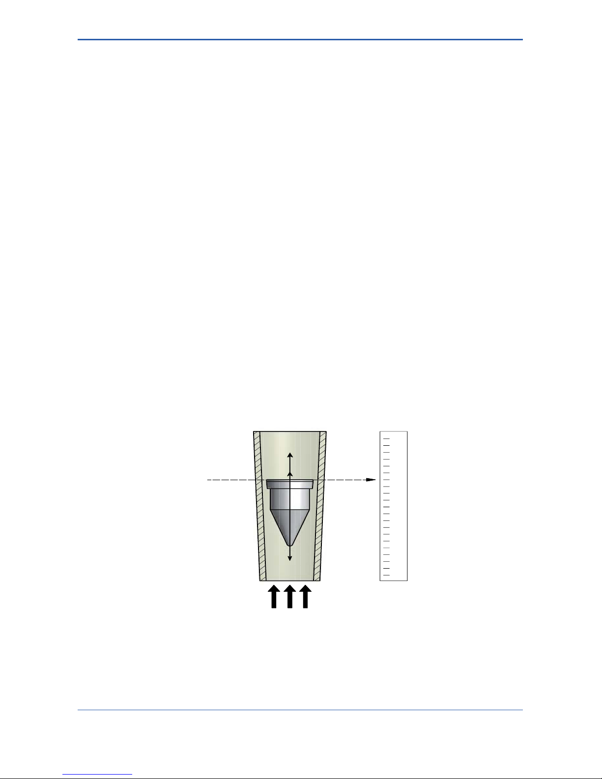
A Rotameter measures the ow of liquids, gases and steam by using a oat inside a conical tube.
The gap between the tube and oat is larger at the top to allow a greater ow to pass through the meter. As gravity
works in a vertical orientation so the tube needs to be vertically oriented.
Rota Yokogawa developed the free rotating oat which stabilises its position in the centre of the cone to provide a
more stable ow measurement.
The medium passes through the metering tube from bottom to top and consequently rises the oat until there is an
annular gap between the inside surface of the metering tube and the oat and equilibrium of the following forces
has been achieved.
Buoyancy / Gravity / Friction force
The Rotameter principle is one of the oldest and mature principles in ow measurement. This mechanical principle
is as simple as it is reliable. The ow is indicated by the top of the oat and can be read from the standard scale on
the metering tube. The RAGN can be equipped with limit switches option /GR2 to /GR8 and /GM1 to /GM5.
All units are calibrated with water or air by the manufacturer. By adjusting the calibration values to the measured
substance’s state of aggregation (density, viscosity), the ow rate scale for each measuring tube can be determined.
When the process conditions have changed the scale is not accurate any longer and the glass tube needs to be
replaced.
1.2 General description
This manual describes installation, operation and maintenance of the RAGN. Please read it carefully before using
this device.
Further, please note that customer features are not described in this manual. When modifying specications,
construction or parts, this manual is not necessarily revised unless it can be assumed that these changes will
impair RAGN functions or performance.
All units are thoroughly tested before shipping. Please check the received units visually to ensure that they
have not been damaged during transport. In case of defects or questions please contact your nearest
YOKOGAWA service centre or sales office. Please describe any defect precisely and indicate model code as
well as serial number.
YOKOGAWA refuses any liability for units which have been repaired by the user without prior consent and do
not meet the specications as a consequence.
1.3 Principle of measurement
1.4 Intended use
The RAGN is designed for the continuous ow measurement of liquids or gases and can be used in all industries.
Typical applications are:
• Visual uid monitoring
• Industrial gas measurement
• Controlling of water circuits
FG = FF + FB = Equilibrium
R
10
20
30
40
50
60
70
80
90
100l/h
Equilibrium
F
G
F
B
F
F

<2. TRANSORTATION AND STORAGE>
2-1
IM 01R01B10-00E-E 4th edition: June 28, 2017-00
All Rights Reserved. Copyright © 2011, Rota Yokogawa
Transportation instructions
When transporting the instrument, you must observe the following safety instructions in order to avoid injury,
damage to the instrument and other material damage.
The steps involved in transport may only be carried out by qualied persons taking into account the safety
instructions.
• Observe the transport instructions on the packaging.
• Observe the below mentioned storage conditions.
• Use only the original packaging.
• The packaging material must be disposed of in accordance with the regulations.
• The transport braces must not be removed until installation.
• Read the chapter “Safety instructions”.
• To avoid any damages, unpack the ow meter only at the installation site.
• Mechanical shocks are to be avoided.
Storage conditions
Please note the following for storage purposes:
• The instrument should be stored in its transport packaging.
• Choose a storage place that meets the following requirements:
• Protection from rain and humidity
• Free of mechanical vibration and shocks
• Ambient temperature between -25 °C – 60 °C
• Atmospheric humidity ranging from 0 – 100 %. Operation above 95 % for longer times is not recommended
Before storing a used ow meter remove any uid from the ow meter and clean it in order to avoid fouling.
Properties of the instrument can change when stored outdoors.
2. Transportation and Storage

<2. TRANPORTATION AND STORAGE>
2-2
IM 01R01B10-00E-E 4th edition: June 28, 2017-00
All Rights Reserved. Copyright © 2011, Rota Yokogawa
Blank Page
<3. PRODUCT DESCRIPTION>
3-1
IM 01R01B10-00E-E 4th edition: June 28, 2017-00
All Rights Reserved. Copyright © 2011, Rota Yokogawa
3. Product description
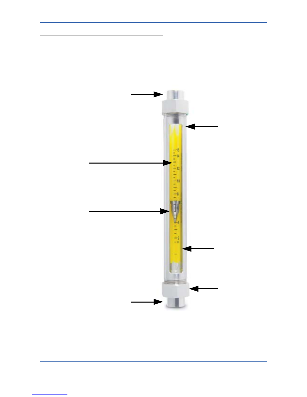
3.1 Metering Tube
Process connection
Process connection
Float
Scale on tube
Nuts
Tubular frame
Splinter shield
<3. PRODUCT DESCRIPTION>
3-2
IM 01R01B10-00E-E 4th edition: June 28, 2017-00
All Rights Reserved. Copyright © 2011, Rota Yokogawa
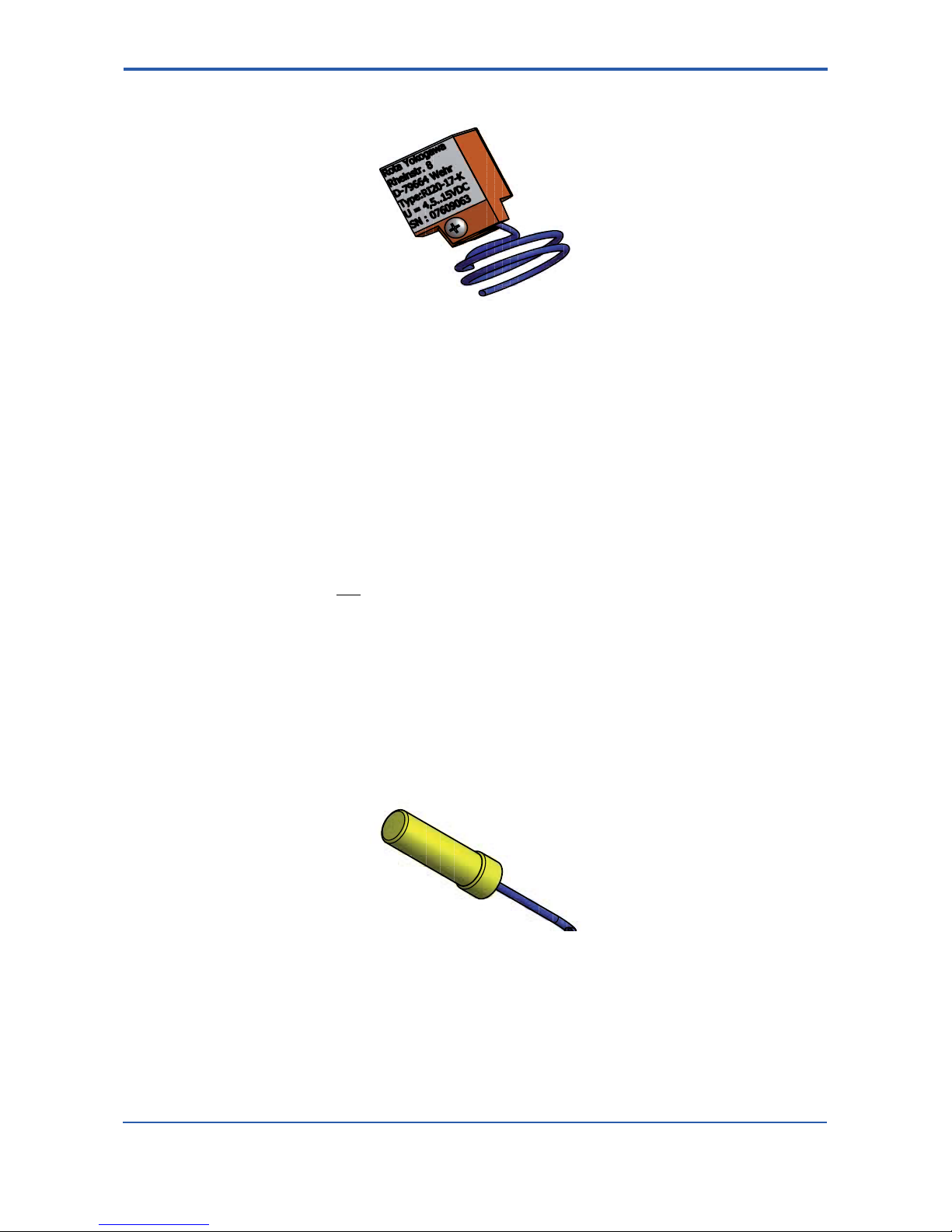
3.2 Bistable inductive ring sensor (Option /GR2 – /GR8)
The ring sensor type RI20 is intended for connection to glass Rotameters. It indicates whether the oat is
positioned above or below the sensor.
The oat must have ferromagnetic properties (e.g. a PVDF oat with iron core).
The device is offered into 3 versions:
Type Option Diameter of tube Possible oat (Yokogawa Code)
RI20-10 G /GR2, /GR6 10mm -PD BN
RI20-17 K /GR3, /GR7 17mm -PD CN
RI20-17 G /GR4, /GR8 17mm -PD DN
The RI20 is bistable, i.e. if the oat is below the switch point, current consumption is always < 1 mA and it is
> 2.2 mA, if the oat is above the switch point. After power on or after power fail the RI20 shows
I < 1 mA. To nd the correct oat position the oat has to move once through the RI20.
It is intended for connection to a non-bistable isolation-switch amplier complying with DIN EN 50227
(NAMUR) (e.g. options /Wxx). With its plastic housing and its sealed-in electronic equipment, the RI20
meets the requirements for protection class IP67 and can also be operated safely in aggressive
atmospheres.
The RI20 is maintenance-free.
See chapter 6 "EXPLOSION PROTECTED TYPE INSTRUMENTS” for devices in ATEX version.
3.3 Magnetic contact (Option /GM1 – /GM5)
The limit switch is mounted to a Rotameter type RAGN, if a magnetic oat is used and indicates if the ow
falls below the set limit (MIN-contact) or exceeds the set limit (MAX-contact).
When reaching the switch point the Reed contact with bias by a permanent magnet opens when the oat
enters the alarm range. The Reed contact closes when the oat leaves the alarm range. Opened or closed
the Reed contact remains because of its bistability in its position no matter how far the oat moves away.
Due to the low switch output of the Reed contact (max, 10 VA/(W), max. 0.5 A, max. 230 V AC) a
transformer isolated barrier (e.g. option /W) should be connected to the GM.
<3. PRODUCT DESCRIPTION>
3-3
IM 01R01B10-00E-E 4th edition: June 28, 2017-00
All Rights Reserved. Copyright © 2011, Rota Yokogawa
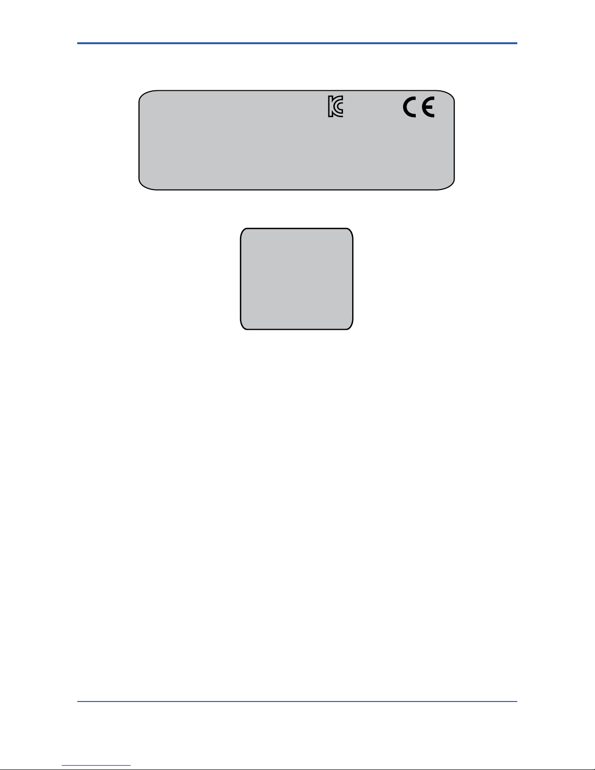
3.4 Marking
Name plate of RAGN:
Name plate of inductive ring sensor (option /GR2 to /GR8)
Rota Yokogaw
Rheinstr. 8
D-79664 Wehr
Type : RI20-10-K
U = 4.5 ... 15V
SN : ..............
ROTA YOKOGAWA D-79664 Wehr
S/N D1L301985
RAGN01-D4SS-L624-TTBLN/B1/B4/L12/V1/GM1/GD/MN/P6/H1
PS:16bar TS:-25°C-100°C PTmax:24bar
100% = 650 l/min Wasser 20°C
Tag-No:123456789012345678901234567890123456789012345
KCC-REMRYG-GR-RAGN
*)
**)
*) only for RAGN04, RAGN05, RAGN06 **) only with option /KC
Rota Yokogaw
Rheinstr. 8
D-79664 Wehr
Type : RI20-10-K
U = 4.5 ... 15V
SN : ..............
Rota Yokogawa
Rheinstr. 8
D-79664 Wehr
Type : RI20-10-K
U = 4.5 ... 15V
SN : ..............

<3. PRODUCT DESCRIPTION>
3-4
IM 01R01B10-00E-E 4th edition: June 28, 2017-00
All Rights Reserved. Copyright © 2011, Rota Yokogawa
Blank Page

<4. INSTALLATION>
4-1
IM 01R01B10-00E-E 4th edition: June 28, 2017-00
All Rights Reserved. Copyright © 2011, Rota Yokogawa
4. Installation
4.1 General
Installation:
All packaging material must be removed. The transportation lock for the oat must be removed.
The piping shall be ushed before installing the owmeter. Piping must be dried for gas applications. Rotameters must be installed vertically. The ow direction is from bottom to top. Prevent the device from mechanical stress and vibration by aligning and supporting the piping. Avoid large volumes of gas downstream and
upstream of the device, this can cause vibration due to compression. Install the On/Off valve downstream in order
to avoid damage when opening the valve. In case of gas applications, increase the ow pressure slowly. Avoid
pressure surges and temperature shocks to the owmeter at any time.
Refer to the pressure and temperature limits of the device. For owmeters with limit switches please see
chapter 4.3, 4.4 and 4.5.
Further installation hints can be found in VDI/VDE 3513 sheet 3.
Commissioning:
When functioning properly, the oat moves freely in the ow. With oats with notches this can be easily seen
by their rotation. If the oat does not move, please check the installation.
The ow rate can be read directly from the scale on the tube. Refer to the scale mark to which the oat adjusts
its top edge when reading.
Maintenance:
With common applications and normal operating conditions the device is maintenance free. In case of soiling
we recommend to clean the measuring tube by using a bottle brush and soap water. Make sure not to scratch
the measuring tube. If oat or measuring tube show signs of wear and tear, we recommend replacing them.
 Loading...