

Page 1
NM 343
NM 253
X1430.A198-8
Page 2

Page 3
1
USER’S MANUAL
ENGLISH
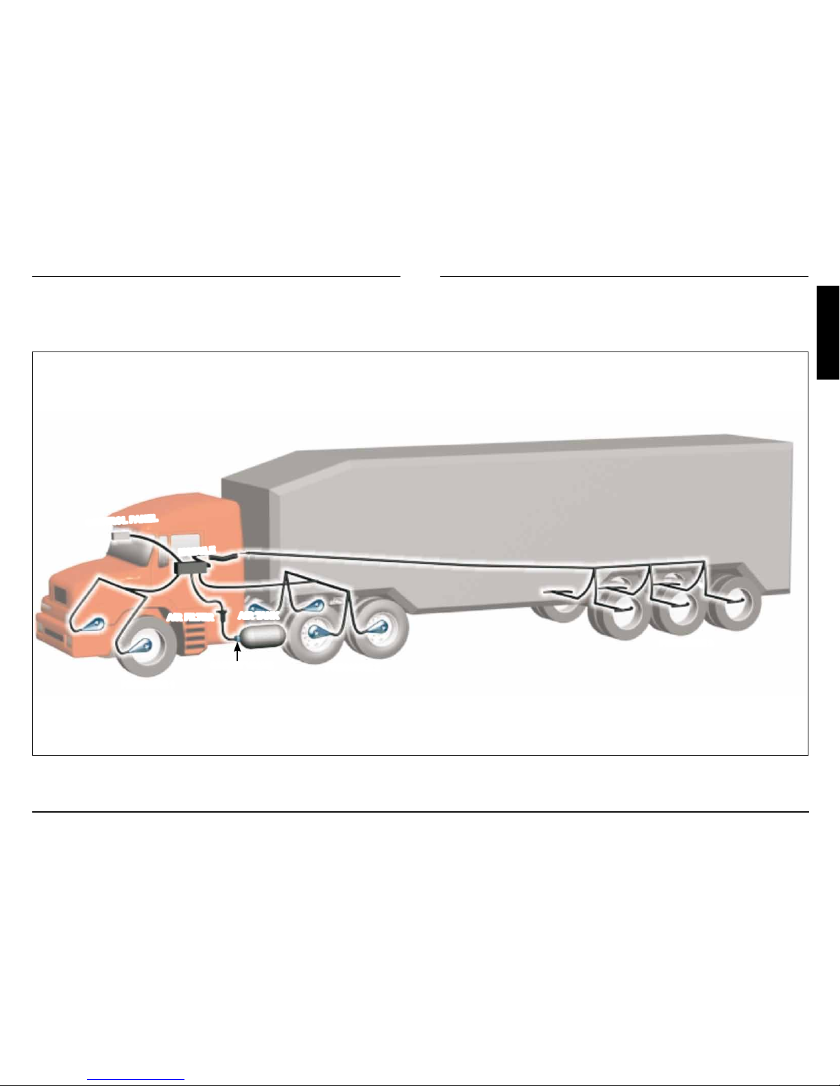
TIRE ELECTRONIC CALIBRATOR
AIR FILTER
PRESSURE 2
SAFETY VALVE
PRESSURE 3
PRESSURE 1
CONTROL PANEL
AIR TANK
MODULE
Page 4
2
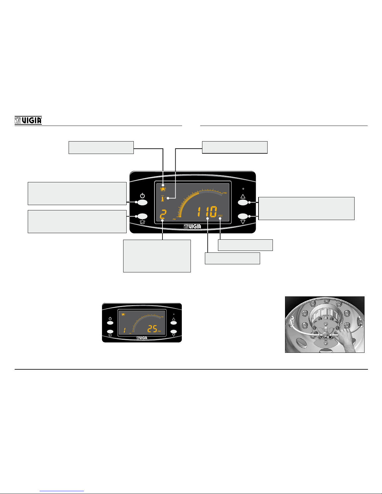
NM 343 MODEL
40
160
60
80
100
120
140
PSI
PSI
PSI
- TURNS THE EQUIPMENT ON/OFF
- DEACTIVATES THE INFLATION PROCESS
IN ONE OR MORE PRESSURES
- ACTIVATES/DEACTIVATES THE ALARM
- CHANGES LIGHT INTENSITY
EQUIPMENT CALIBRATINGSOUND SIGNAL ENABLED
- VALUES UP/DOWN
- SELECTION OF A PRESSURE SYSTEM
- MANUAL/SEQUENTIAL MODE
MEASSURING UNIT
PRESSURE VALUE
DIGITAL INDICATOR:
1= PRESSURE 1
2= PRESSURE 2
3= PRESSURE 3
P= AIR SUPPLY PRESSURE
HOW TO DETERMINE THE ORIGIN OF THE LOSS
IN THE VIGIA EQUIPMENT:
40
3
BAR
160
11
BAR
60
80
100
120
140
BAR
PSI
4
5
6
7
8
9
10
PSI
PSI
40
160
60
80
100
120
140
PSI
PSI
PSI
Set to manual mode and
cancel the pressure with
air loss. If the pressure
in the control panel drops
and the pressure in every
tire remains the same, the
air loss is in the air network
of the VIGIA equipment.
IN THE TIRE:
Activate the equipment
and verify the hoses
close to the tires. The
one that vibrates, is the
puncture one.
Page 5
3
USER’S MANUAL
ENGLISH
Functioning
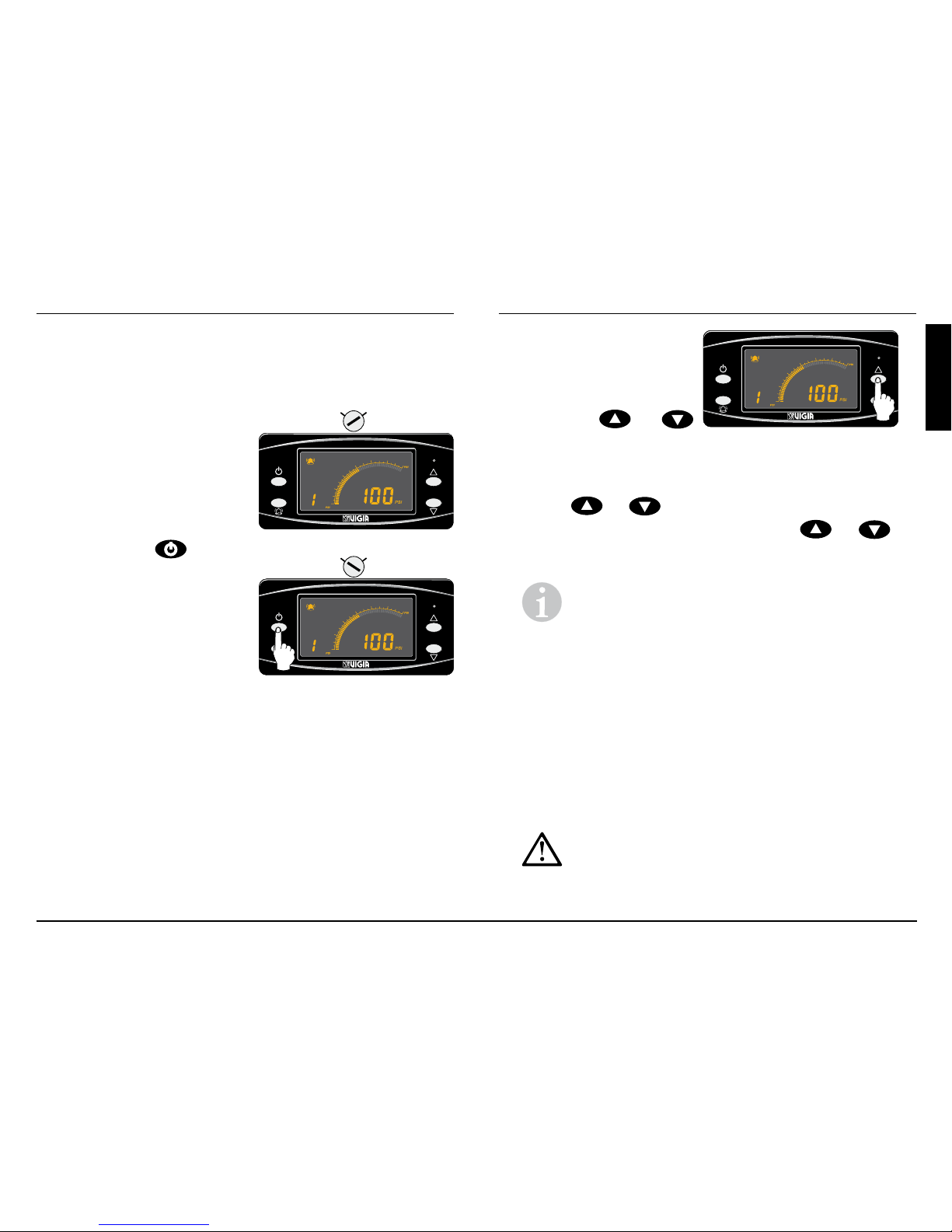
Activation
The equipment
automatically turns on
when switching on the
ignition key and it turns off
when closing it.
40
160
60
80
100
120
140
BAR
PSI
PSI
PSI
40
160
60
80
100
120
140
PSI
PSI
PSI
ON
ONOFF
However, you can turn the
equipment on and off by
pressing the
button
for ± 4 seconds even with
the ignition key closed, but
it will not inate the tires.
You could only see thre
pressures going into manual
mode.
40
160
60
80
100
120
140
PSI
PSI
PSI
40
160
60
80
100
120
140
PSI
PSI
PSI
ON
ONOFF
Visualization
The panel shows the pressures in sequential or
manual mode.
Sequential mode: Each pressure is shown
automatically every 10 seconds, i.e. 10 seconds
pressure 1, then 10 seconds pressure 2, then 10
seconds pressure 3 and then it shows again pressure
1 and so on.
Manual mode: In case
40
160
60
80
100
120
140
PSI
PSI
PSI
40
160
60
80
100
120
140
PSI
PSI
PSI
3 SECONDS
you want to see just one
pressure constantly, it can
be congured manually
by pressing
or
for 3 seconds.
Once congured in manual mode, pressures 1, 2, 3
or more can be seen and also the inlet pressure P by
pressing
or .
To change to sequential mode, press
or
for
3 seconds.
Explanation: In case there is a loss of pressure
(punctured tire) the panel will automatically change
to sequential mode to advice the driver about such situation.
Air loss
The control panel will indicate the air loss with a sound
signal:
Small air loss: 1 beep every 9 seconds.
Medium air loss: 2 beeps every 5 seconds.
Excessive air loss: 3 beeps every 2 seconds.
Important:
Repair the air loss as soon as possible
or go to the nearest Ofcial Service.
Page 6
4
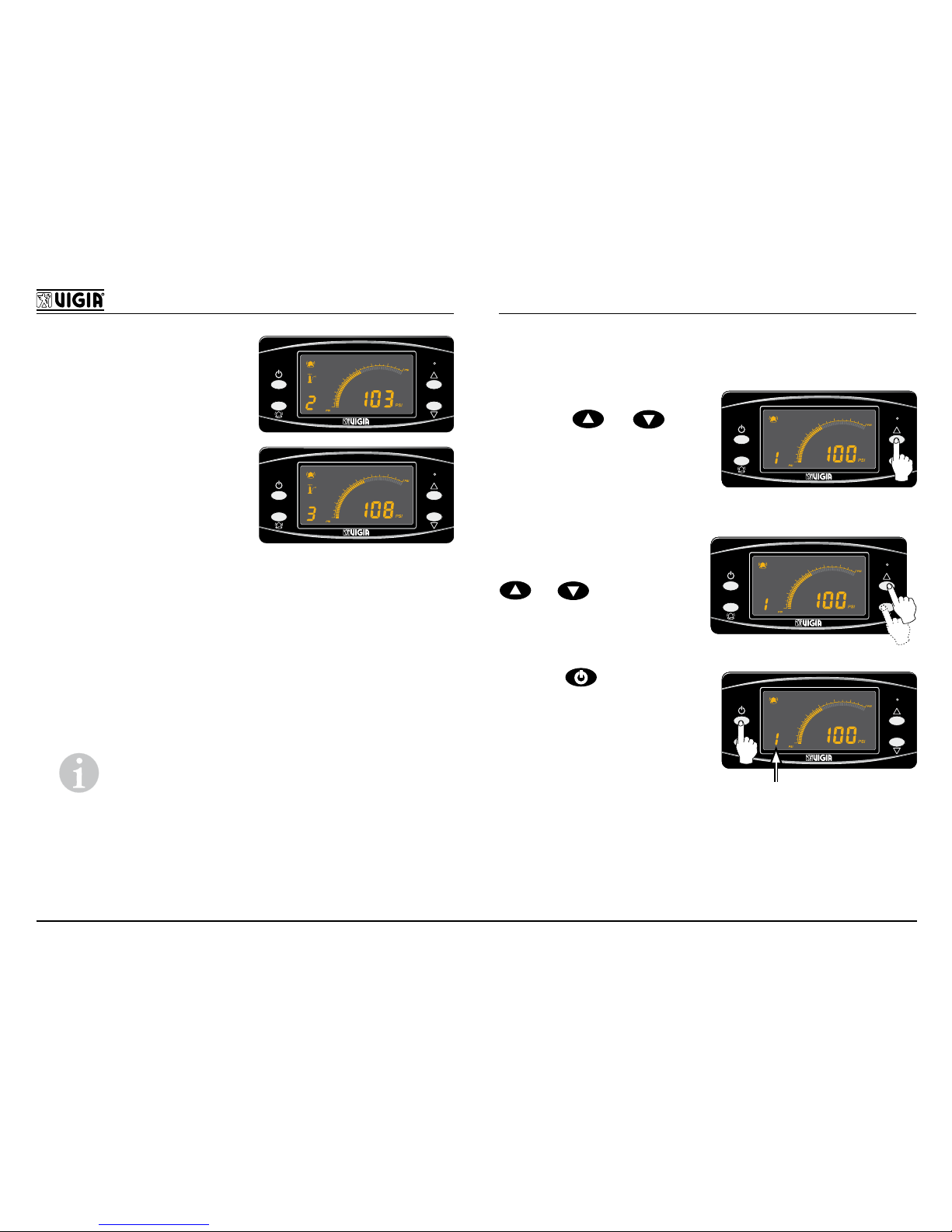
If there is an air loss in more
40
160
60
80
100
120
140
PSI
PSI
PSI
10 SECONDS
than one pressure, the control panel will only indicate
the pressures with air loss
sequentially.
For example: If there is an
air loss in pressures 2 and
3, the display will indicate
pressure 2 for 10 seconds,
then pressure 3 for 10
seconds and so on, but it
will not indicate pressure 1.
40
160
60
80
100
120
140
PSI
PSI
PSI
10 SECONDS
Excessive air loss
When there is low pressure in the air tank (below 80
PSI), the equipment will deactivate automatically and
it will indicate the inlet pressure P warning the driver
with 3 beeps every 2 seconds.
Explanation:
If there is a pressure calibrating, it
indicates the P sequentially and the pressure at
issue (1, 2 or 3).
Cancellation
If you want to cancel a pressure, proceed as follows:
- Set to manual mode
pressing
or for 3
seconds.
40
160
60
80
100
120
140
PSI
PSI
PSI
40
160
60
80
100
120
140
PSI
PSI
PSI
3 SECONDS
- Select the pressure you
want to cancel pressing
or .
40
160
60
80
100
120
140
PSI
PSI
PSI
40
160
60
80
100
120
140
PSI
PSI
PSI
- Press , one warning
beep will sound and the
number will blink indicating
that such pressure was
cancelled.
40
160
60
80
100
120
140
PSI
PSI
PSI
40
160
60
80
100
120
140
PSI
PSI
PSI
BLINKING
To enable the pressure
again, follow the 3 steps mentioned or close and open
the ignition key.
Page 7
5
USER’S MANUAL
ENGLISH
Alarm
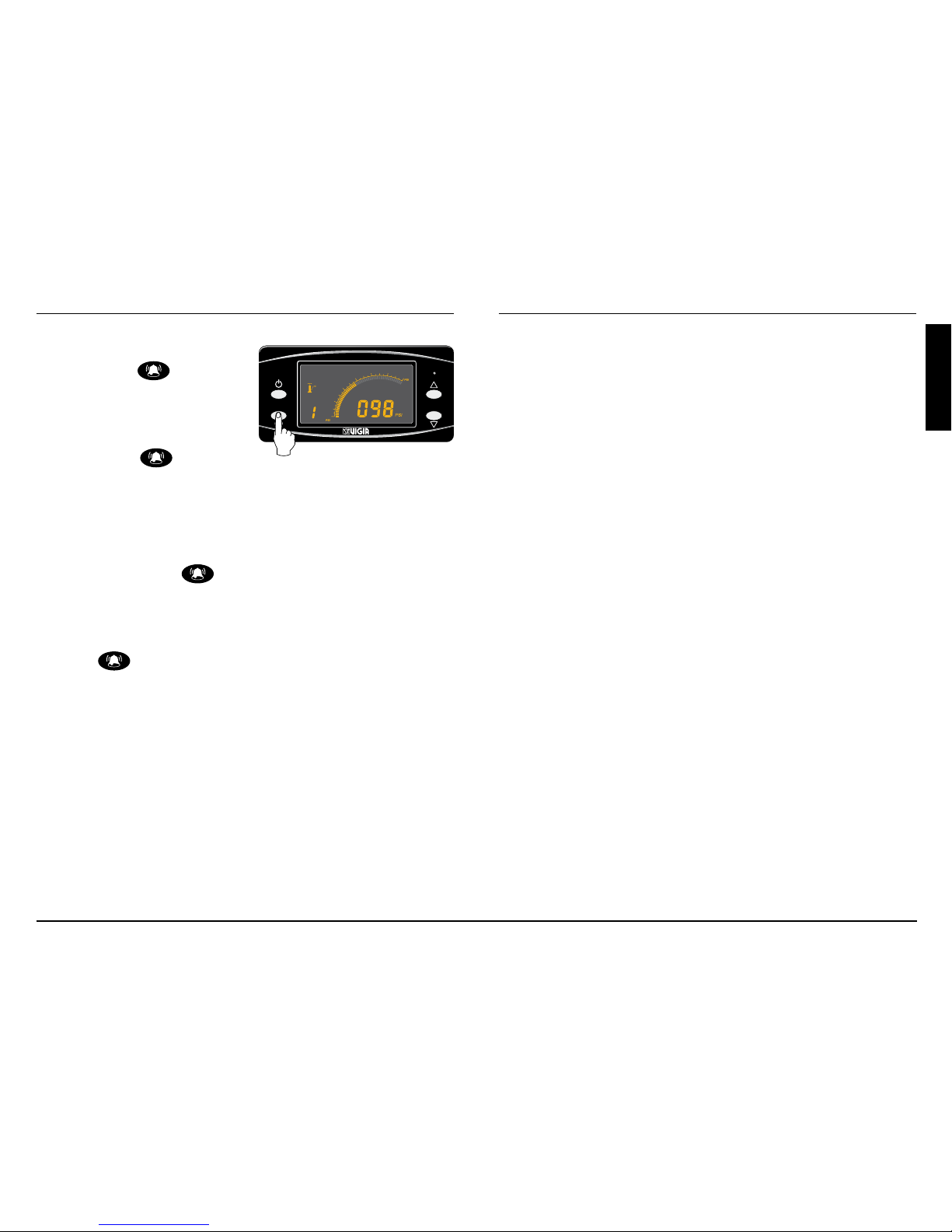
If you want to cancel the
alarm, press
however,
if the air loss remains it will
automatically activate after
20 minutes being able to
cancel again
.
40
160
60
80
100
120
140
PSI
PSI
PSI
Light intensity of the display
If you want to change the light intensity of the display,
hold down the key
what will increase the intensity
until the maximum and then it will decrease to the
minimum limit to increase again and so on.
Whenever it shows the desired light intensity, release
the key
.
Page 8
6
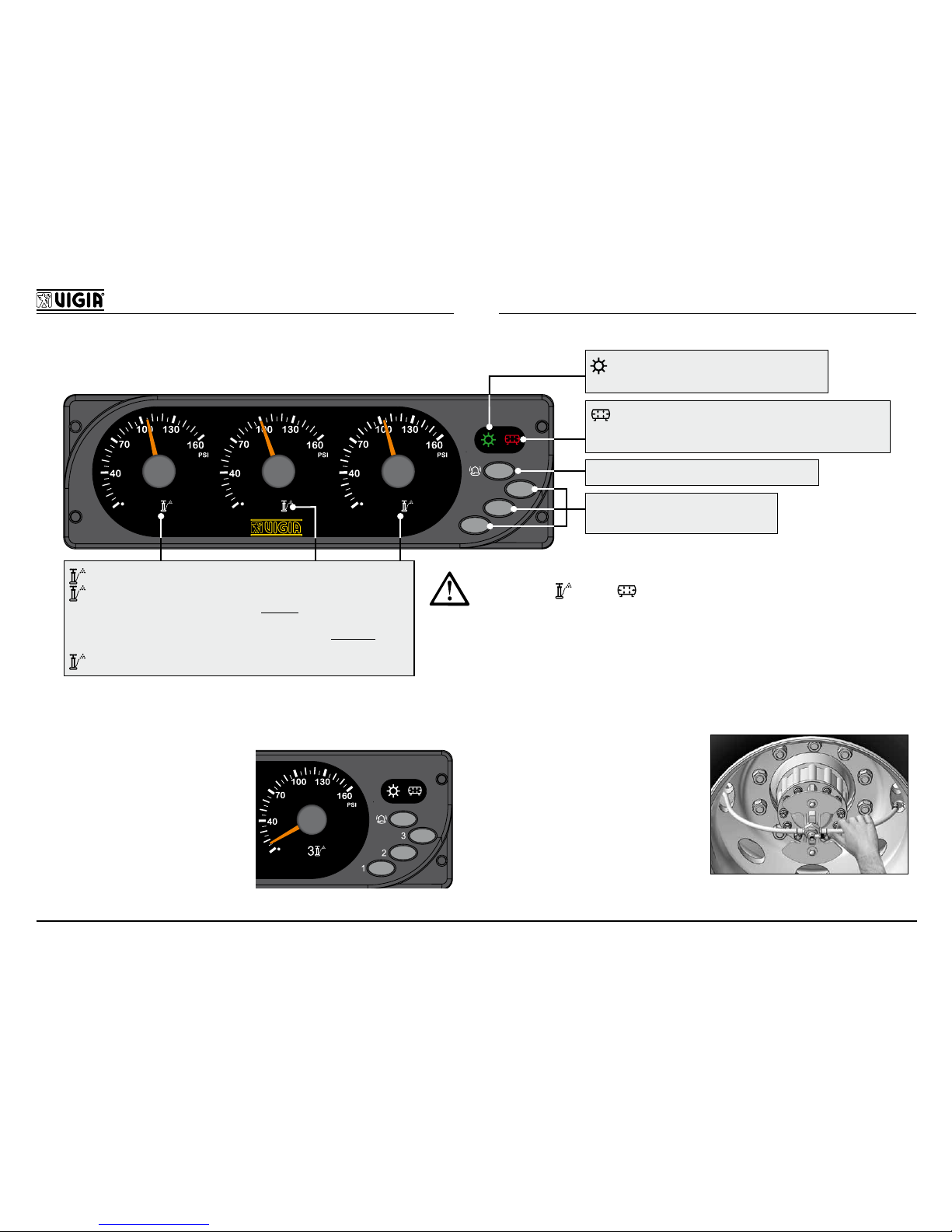
NM 253 MODEL (Exclusive for México)
1
2
3
3
2
1
OFF: Correct pressure in tires.
YELLOW: PERMANENTLY ON: Equipment recovering a loss of
great magnitude. The alarm goes off. Danger: Stop the engine and
repair inmediately.
BLINKING: Equipment calibrating. The alarm goes off. Warning: Repair
the loss as soon as possible.
RED: ON: Circuit off.
GREEN: ON: Equipment activated.
OFF: Equipment deactivated.
ACTIVATES / DEACTIVATES THE ALARM
ACTIVATES / DEACTIVATES THE
CORRESPONDING PRESSURE
RED: ON: Low air pressure in the tank or high tem-
perature in the electrovalves of the equipment module or
equipment deactivated. The alarm goes off.
- If the loss is extreme and the compressor cannot compensate it,
the yellow leds
and red will blink alternately.
In this case, stop the vehicle and repair the loss.
HOW TO DETERMINE THE ORIGIN OF THE LOSS
IN THE VIGIA EQUIPMENT:
Cancel the desired circuit
by pressing the 1, 2 or
3 switch. If the indicator
drops and the pressure in
every tire remains, the air
loss is in the air network
of the VIGIA equipment.
IN THE TIRE:
Activate the equipment
and verify the hoses
close to the tire. The
one that vibrates is the
punctured tire.
Page 9
7
USER’S MANUAL
ENGLISH
INFLATION PRESSURE IMPORTANCE
There is no doubt that pressure is the main factor that
directly affects tires performance.
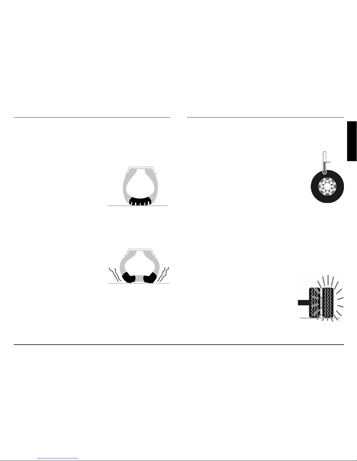
Pressure excess
Tires do not absorb impacts,
producing cracks and damages; such as extreme wear in
the middle.
The tread surface is reduced
and the trim starts to slip resulting the loss of traction.
Lack of pressure
It produces an increase in
bending movements. This
cause overheating, damages
in the fabric, steel wires and
separation of the tread; as well
as the extreme wear of the tire
shoulders.
How to understand pressure variance in
tires and the VIGIA electronic calibrator
Calibration:
AMBIENT
TEMPERATURE
Tires should be calibrated at ambient
temperature, according to the “loading
and pressure tables” provided by the
manufacturer.
The tire pressure may increase more
than 18% of the calibrated pressure due
to rolling temperature.
The VIGIA equipment will indicate this pressure
increase on the gauges. Its functioning is correct.
Never deate tires when there is an increase of
pressure caused by rolling.
Punctured tire:
In case of puncture the VIGIA
equipment will increase the pressure
to the cold calibrated pressure
without taking into account the
increase of pressure caused by
rolling.
For this reason, it is very important
to repair the tire damaged as soon
as possible.
Page 10
8
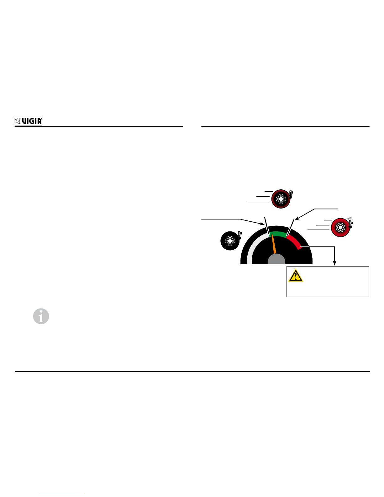
Overpressure caused by rolling:
A particular feature of the VIGIA equipment is that it
can indicate the overpressure causde by rolling of
tires, provided that certain conditions are met:
- That there are no air losses in the VIGIA equip-
ment and in tires.
- There should be balance of pressure between
the VIGIA system and the tires (the control panel
should indicate 100 PSI and tires should have that
pressure).
- The VIGIA ination valve be in excellent conditions
and working.
When there is a pressure balance between the VIGIA
equipment and the tires, the ination valve is in neutral
status. When rolling, tires increase their temperature,
therefore the internal pressure increases too and the
VIGIA valve releases air due to the vibrations produced by the imperfections of the road.This overpressure
goes into the VIGIA network and the control panel will
indicate this phenomenon.
Note: The overpressure may not be
the same in every tire, in this case the
VIGIA equipment will indicate the minimum
one.
If while running, the VIGIA equipment indicates an
extreme increase on the calibrated pressure – more
than 18% – you should analyze the causes of this
situation. In this case, the VIGIA equipment will be
indicating indirectly certain problems:
NORMAL
ABNORMAL
+ 18 %
Calibration
recommended by
manufacturer
INFORM ABOUT THIS
SITUATION TO THE
MAINTENANCE MANAGER.
DON NOT TOUCH THE VIGIA
EQUIPMENT
Page 11
9
USER’S MANUAL
ENGLISH
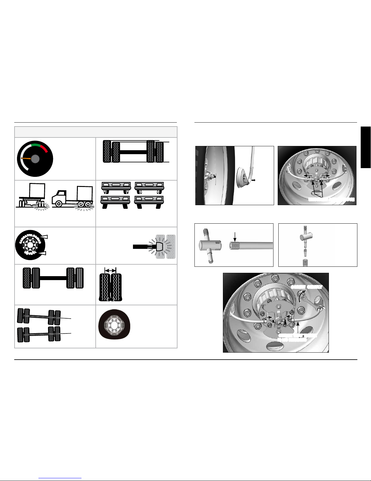
POSSIBLE CAUSES ABOUT ABNORMAL OVERPRESSURE
COLD
CALIBRATING
PRESSURE LOW
DIFFERENT PERIMETERS AMONG
TIRES
WRONG LOAD DISTRIBUTION
TROUBLES IN DAMPING,
SUSPENSION, STEERING OR
ALIGNMENT SYSTEM
C
A
R
G
A
/
V
E
L
O
C
I
D
A
D
T
A
M
A
Ñ
O
WRONG CHOICE OF
THE TYPE / SIZE OF
TIRE WITH RESPECT
TO THE LOAD /
SPEED
TROUBLES WITH THE
BRAKING SYSTEM
DIFFERENT TYPES OF TIRES IN
THE SAME AXLE
WRONG DISTANCE
BETWEEN TIRES
AXLES NOT
PARALLEL
OVAL RIM
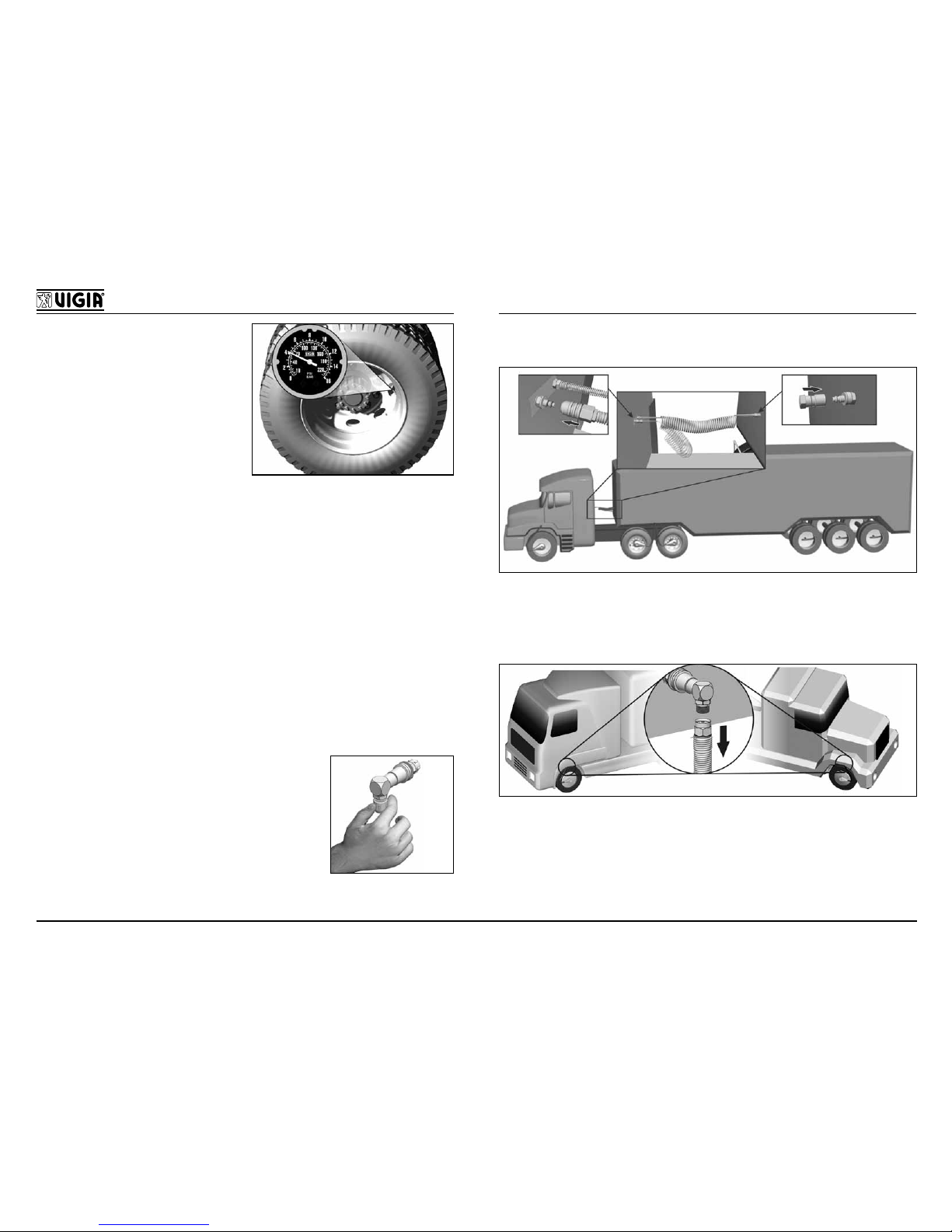
TIRE REPLACEMENT
Remove the tire, without damaging the rotor.
UNSCREW AND REMOVE
REMOVE
Reinstall the VIGIA ination valve in the new tire.
CLEAN THE EXTERNAL THREAD
REMOVE THE OVUM
CHECK THAT THERE
IS NO RUBBING
SCREW GENTLY
Page 12
10
Verify that the ination
pressure of the tire is
lower than prefault calibration. The equipment
will be in charge to calibrate it. The system only
provides air to the tires,
it do not deate them.
ADVICES
ü Verify the centering of the rotor every time the hub is
dissasembled to repair the breaks, make adjustments
or replace bearings.
ü Clean the air lter every 6 months.
ü Do not modify the calibration registers.
ü Repair the damaged tire as soon as possible.
ü Every 4 months, deate tires at a lower pressure
than the calibrated one and let the VIGIA equipment to
calibrate them again.
ü Partial cancelling: In case of
air loss in the connections to the
tires, cancel it putting with the plug
provided in the coupling of the
bodywork. Contact the closest
Ofcial Service.
ü Before uncoupling, disconnect the spiral tube.
ü Before tilting the cabin, disconnect the couplings of
the bodywork.
Page 13
11
MANUAL DEL USUARIO
ESPAÑOL
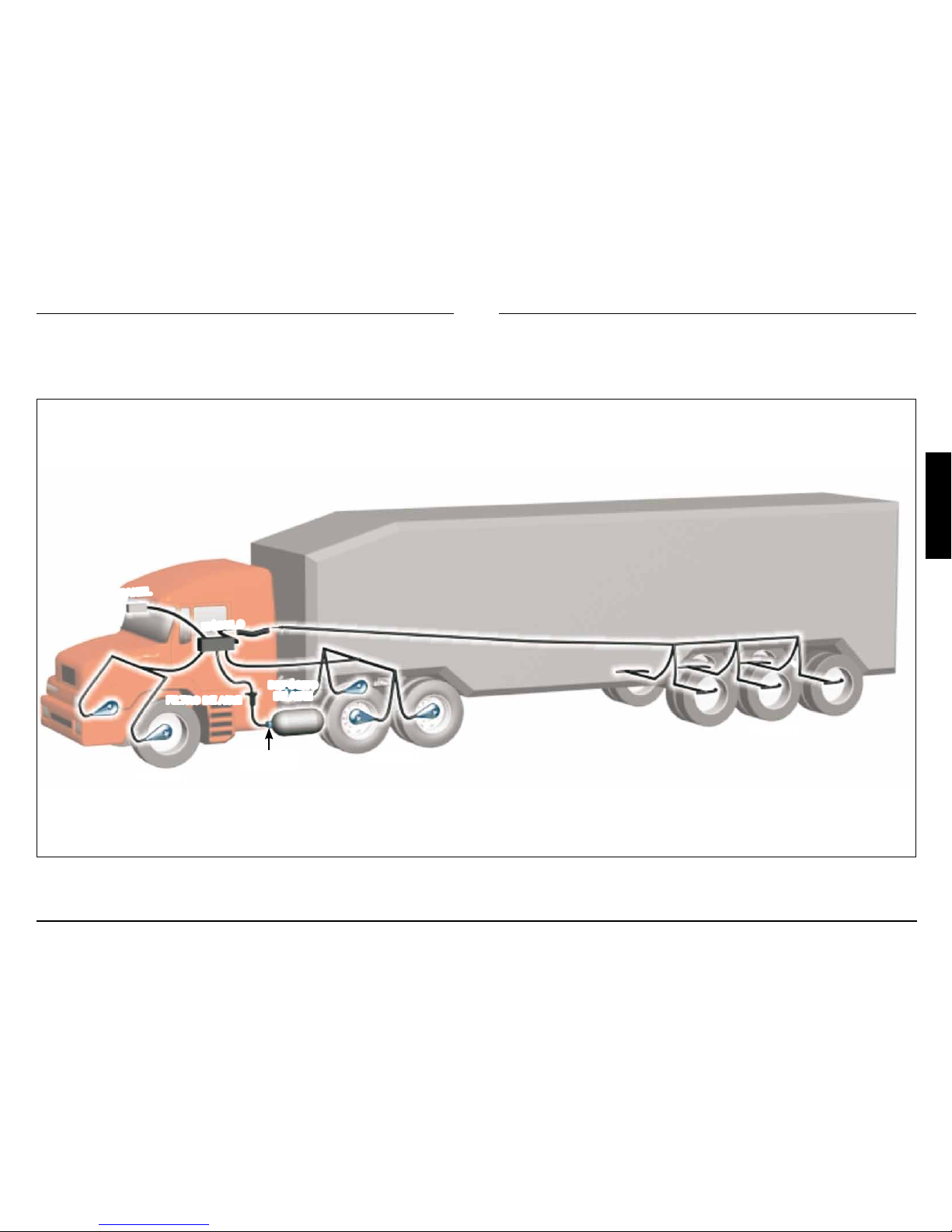
CALIBRADOR ELECTRÓNICO DE LLANTAS
FILTRO DE AIRE
PRESIÓN 2
VÁLVULA DE
SEGURIDAD
PRESIÓN 3
PRESIÓN 1
PANEL
DEPÓSITO
DE AIRE
MÓDULO
Page 14
12
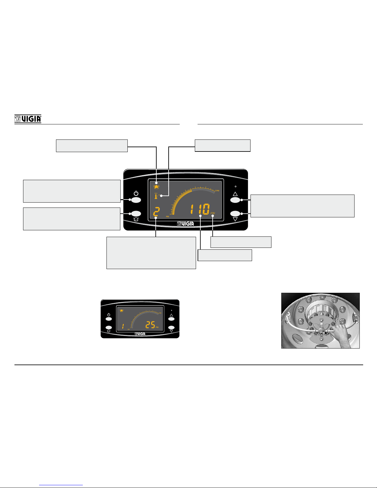
MODELO NM 343
40
160
60
80
100
120
140
PSI
PSI
PSI
- ENCIENDE/APAGA EL EQUIPO
- DESACTIVA EL PROCESO DE INFLADO EN
UNA O MÁS PRESIONES
- HABILITA/DESHABILITA LA ALARMA
- CAMBIA LA INTENSIDAD LUMÍNICA
EQUIPO CALIBRANDOSEÑAL SONORA HABILITADA
- AUMENTA/DISMINUYE VALORES
- SELECCIONA UN SISTEMA DE PRESIÓN
- INGRESA A MODO MANUAL/SECUENCIAL
UNIDAD DE MEDICIÓN
VALOR DE PRESIÓN
DÍGITO INDICADOR:
1= PRESIÓN 1
2= PRESIÓN 2
3= PRESIÓN 3
P= PRESIÓN DE ALIMENTACIÓN DE AIRE
COMO DETERMINAR EL ORIGEN DE LA PÉRDIDA
EN EL EQUIPO VIGIA:
40
3
BAR
160
11
BAR
60
80
100
120
140
BAR
PSI
4
5
6
7
8
9
10
PSI
PSI
40
160
60
80
100
120
140
PSI
PSI
PSI
Congurar a modo
manual y anular la presión
que presenta pérdida. Si
la presión en el panel cae
y la presión de todas las
llantas se mantiene, la
pérdida está en la red de
aire del equipo VIGIA.
EN LA LLANTA:
Activar el equipo y tocar
las mangueras cerca de
las llantas. La que vibra
determina cuál de ellas
es la ponchada.
Page 15

13
MANUAL DEL USUARIO
ESPAÑOL
Funcionamiento
Activación
El equipo se enciende
automáticamente al colocar
la llave en contacto y se
apaga al cerrar la misma.
40
160
60
80
100
120
140
BAR
PSI
PSI
PSI
40
160
60
80
100
120
140
PSI
PSI
PSI
ON
ONOFF
No obstante se puede
encender y apagar el equipo
manteniendo presionado
por ± 4 segundos
aún con llave de contacto
cerrada, pero éste no inará
las llantas, solamente
se podrán visualizar las
presiones entrando a modo
manual.
40
160
60
80
100
120
140
PSI
PSI
PSI
40
160
60
80
100
120
140
PSI
PSI
PSI
ON
ONOFF
Visualización
El panel puede mostrar las presiones de modo
secuencial o manual.
Modo Secuencial: Cada presión se muestra por 10
segundos cada una en forma automática, es decir 10
segundos la presión 1, luego 10 segundos la presión
2, luego 10 segundos la presión 3 y luego pasa
nuevamente a la presión 1 y así sucesivamente.
Modo Manual: En caso
40
160
60
80
100
120
140
PSI
PSI
PSI
40
160
60
80
100
120
140
PSI
PSI
PSI
3 SEGUNDOS
que desee visualizar
solamente una presión en
forma constante se puede
congurar a modo manual
manteniendo presionado
o
por 3 segundos. Una vez congurado en
modo manual se pueden visualizar las presiones 1, 2,
3 (o más) y la presión de entrada P presionando las
teclas
o .
Para cambiar a modo secuencial mantener presionado
o
por 3 segundos.
Aclaración: En caso que exista una pérdida de
presión (llanta ponchada) el panel se pasa automáticamente a modo secuencial para informar al conductor dicha situación.
Pérdida de Aire
El panel indicará la magnitud de la pérdida de aire en
forma sonora:
Pérdida pequeña: 1 beep cada 9 segundos.
Pérdida media: 2 beep cada 5 segundos.
Pérdida excesiva: 3 beep cada 2 segundos.
Importante: Reparar la pérdida a la brevedad o
recurrir al Servicio Ocial más cercano.
Page 16
14
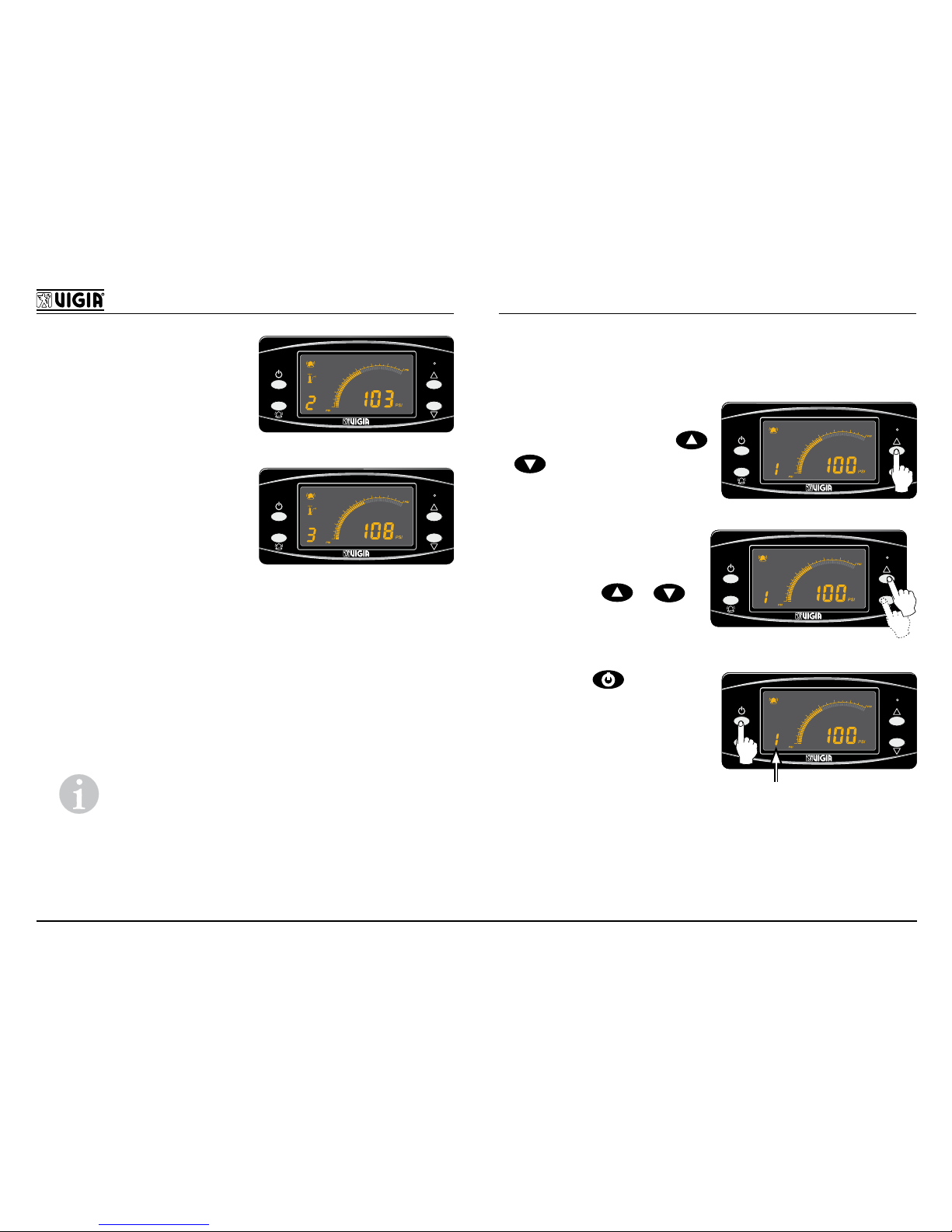
Si se genera una pérdida
40
160
60
80
100
120
140
PSI
PSI
PSI
10 SEGUNDOS
de aire en más de una
presión, el panel indicará
solamente las presiones
con pérdida en modo
secuencial.
Por ejemplo: Si existe
pérdida de aire en las
presiones 2 y 3 el display
indicará la presión 2 por 10
segundos, luego la presión
3 por 10 segundos y así
sucesivamente pero no
indicará la presión 1.
40
160
60
80
100
120
140
PSI
PSI
PSI
10 SEGUNDOS
Caída de Presión Excesiva
Al existir baja presión de aire en el depósito (por debajo
de 80 PSI), el equipo se desactiva automáticamente y
comienza a indicar la presión de entrada P advirtiendo
al conductor con 3 beep cada 2 segundos.
Aclaración: Si hay una presión que está
calibrando, indica secuencialmente la P y la presión en cuestión (1, 2 o 3).
Anulación
Si se desea anular una presión, proceder de la
siguiente manera:
- Congurar a modo
manual presionando
o
por 3 segundos.
40
160
60
80
100
120
140
PSI
PSI
PSI
40
160
60
80
100
120
140
PSI
PSI
PSI
3 SEGUNDOS
- Seleccionar la presión
que se desee anular
presionando
o .
40
160
60
80
100
120
140
PSI
PSI
PSI
40
160
60
80
100
120
140
PSI
PSI
PSI
- Presionar ,sonará 1
beep de aviso y quedará
titilando el número de
dicha presión indicando
que la misma quedó
anulada.
40
160
60
80
100
120
140
PSI
PSI
PSI
40
160
60
80
100
120
140
PSI
PSI
PSI
TITILANDO
Para habilitar nuevamente esa presión realizar los
3 pasos mencionados o cerrar y abrir la llave de
contacto.
Page 17
15
MANUAL DEL USUARIO
ESPAÑOL
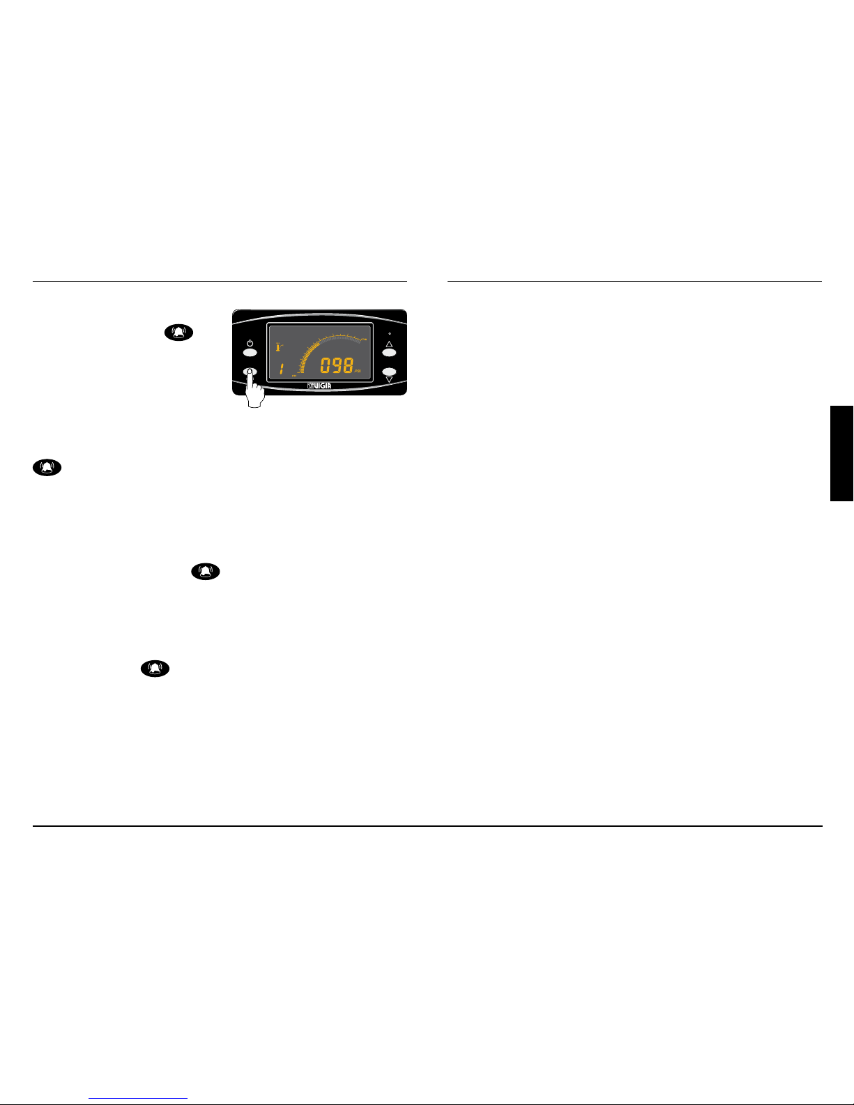
Alarma
Si se desea anular la
alarma presionar
no
obstante si la pérdida
de presión continúa se
activará automáticamente
luego de transcurrir 20
minutos, pudiéndose anular
nuevamente presionando
.
40
160
60
80
100
120
140
PSI
PSI
PSI
Intensidad Lumínica del Display
Si se desea modicar la intensidad lumínica del display
mantener presionado
a lo que irá aumentando
la intensidad hasta llegar a un máximo y luego caerá
a un mínimo para ir aumentando nuevamente y así
sucesivamente.
En el momento que muestre la intensidad lumínica
deseada soltar
.
Page 18
16
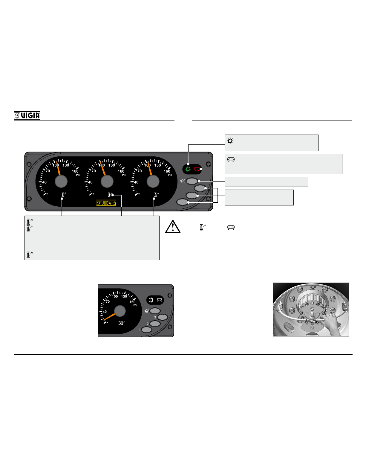
MODELO NM 253 (Exclusivo para México)
1
2
3
3
2
1
APAGADO: Presión correcta de las llantas.
AMARILLO: ENCENDIDO FIJO: Equipo recuperando una
pérdida de gran magnitud. Suena la alarma. Peligro: Detener la marcha
y reparar inmediatamente.
TITILANDO: Equipo calibrando. Suena la alarma. Precaución: Reparar
a la brevedad la pérdida.
ROJO: ENCENDIDO: Circuito apagado.
VERDE: ENCENDIDO: Equipo activado.
APAGADO: Equipo desactivado.
HABILITA / DESHABILITA LA ALARMA
HABILITA / DESHABILITA LA
PRESIÓN CORRESPONDIENTE
ROJO: ENCENDIDO: Baja presión en el depósito de
aire o alta temperatura en las electroválvulas del módulo o
equipo desactivado. Suena la alarma.
- Si la pérdida es excesiva y el compresor no logra compensarla,
los leds
amarillo y rojo parpadearán alternadamente.
En ese caso, detener el vehículo y reparar la pérdida.
COMO DETERMINAR EL ORIGEN DE LA PÉRDIDA
EN EL EQUIPO VIGIA:
Anular el circuito de aire
deseado expulsando el
interruptor 1, 2 o 3. Si la
aguja cae y la presión
de todas las llantas se
mantiene, la pérdida
está en la red de aire del
equipo VIGIA.
EN LA LLANTA:
Activar el equipo y tocar
las mangueras cerca de
las llantas. La que vibra
determina cuál de ellas
es la ponchada.
Page 19
17
MANUAL DEL USUARIO
ESPAÑOL
IMPORTANCIA DE LA PRESIÓN DE
INFLADO
La presión es, sin duda, el principal factor que afecta
directamente al rendimiento de las llantas.
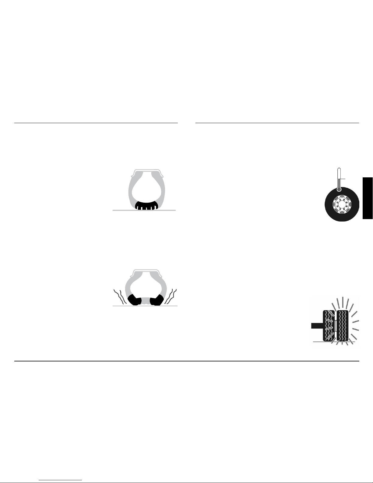
Exceso de presión
Las llantas no absorben los
impactos, produciéndose roturas y grietas; así como el desgaste excesivo en el centro.
La supercie de la banda de rodamiento se reduce,
haciendo patinar a la llanta, con la consiguiente pérdida de tracción.
Falta de presión
Produce un aumento de la
exión. Esto genera exceso
de calor, rotura de telas, alambres de acero y separación de
la banda de rodamiento; así
como el desgaste excesivo de
los hombros de la llanta.
Cómo interpretar las variaciones de
presión de las llantas y el Calibrador
Electrónico VIGIA
Calibración:
TEMPERATURA
AMBIENTE
Las llantas deben calibrarse en FRÍO
(temperatura ambiente). De acuerdo
a la “Tabla de Cargas y Presiones”
suministrada por el fabricante.
El aumento de presión debido a la
temperatura por rodamiento de las
llantas, puede llegar hasta un 18% más
que la presión de calibrado.
El equipo VIGIA indicará en los manómetros este
aumento de presión. Su funcionamiento es correcto.
Nunca desinar las llantas ante el aumento de
presión generada por rodamiento.
Llanta ponchada:
En caso de un pinchazo el equipo
VIGIA llevará a la llanta a la presión
de calibrado en frío sin atender al
aumento de presión generada por
rodamiento.
Por esto es importante reparar la
llanta dañada a la brevedad.
Page 20
18
Sobrepresión generada por rodamiento:
El equipo VIGIA tiene la particularidad de indicar la
sobrepresión generada por rodamiento de las llantas,
siempre y cuando se cumplan ciertas condiciones:
- Que no existan pérdidas ni en el equipo VIGIA ni
en las llantas.
- Que exista equilibrio de presiones entre el sistema
VIGIA y las llantas (o sea que el panel indique, por
ejemplo, 100 PSI y las llantas tengan 100 PSI).
- Que las válvulas de inado VIGIA estén en per-
fecto estado de uso y funcionamiento.
Lo que ocurre es que al existir equilibrio de presiones entre el equipo VIGIA y las llantas, la válvula de
inado queda en un estado neutral. Al rodar, las llantas van tomando temperatura, por consiguiente su
presión interna aumenta y va escapando a través de
la válvula VIGIA debido a las vibraciones que tiene
la misma por efecto de las imperfecciones del pavimento. Esa sobrepresión ingresa a la red del equipo
VIGIA y el panel irá indicando ese fenómeno.
Nota: Puede ocurrir que la sobrepre-
sión no sea igual en todos las llantas,
en este caso el equipo VIGIA indicará la
mínima.
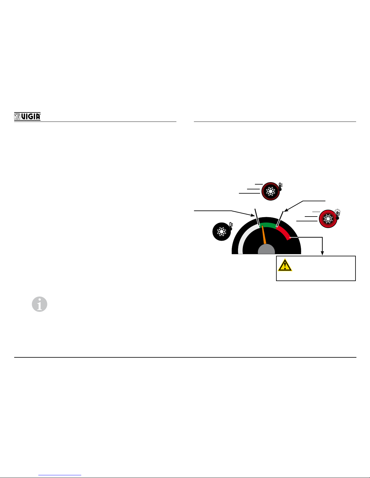
Si durante el rodamiento, el equipo VIGIA acusa un
aumento considerable de la presión de calibrado –
más del 18% – debe analizarse el por qué de esta
situación. En este caso el equipo VIGIA estará indicando en forma indirecta ciertos problemas:
NORMAL
ANORMAL
+ 18 %
Calibración
recomendada
por fabricante
INFORMAR ESTA SITUACIÓN
AL RESPONSABLE DE
MANTENIMIENTO.
NO TOCAR EL EQUIPO VIGIA
Page 21
19
MANUAL DEL USUARIO
ESPAÑOL
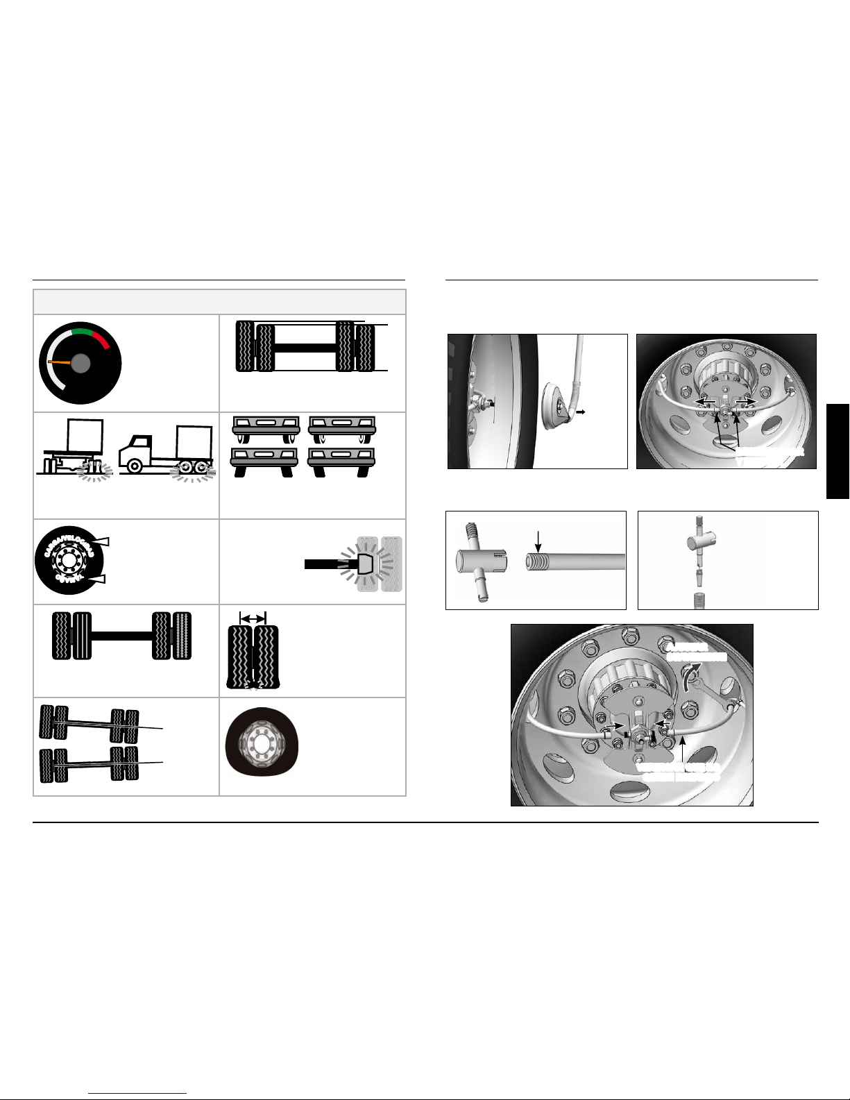
POSIBLES CAUSAS DE SOBREPRESIÓN ANORMAL
PRESIÓN DE
CALIBRACIÓN
EN FRÍO BAJA
PERÍMETROS DIFERENTES ENTRE
LLANTAS
MALA DISTRIBUCIÓN DE LA
CARGA
PROBLEMAS EN LOS SISTEMAS DE
AMORTIGUACIÓN, SUSPENSIÓN,
DIRECCIÓN O ALINEACIÓN
C
A
R
G
A
/
V
E
L
O
C
I
D
A
D
T
A
M
A
Ñ
O
MALA ELECCIÓN DEL
TIPO / MEDIDA DE LA
LLANTA RESPECTO
DE LA CARGA/
VELOCIDAD
PROBLEMAS EN LOS
SISTEMAS DE FRENO
TIPOS DE LLANTAS DIFERENTES
EN UN MISMO EJE
SEPARACIÓN
INCORRECTA
ENTRE LLANTAS
EJES NO
PARALELOS
RING OVALADO
REEMPLAZO DE LLANTA
Retirar la llanta, cuidando de no dañar el rotor.
DESENROSCAR
Y RETIRAR
RETIRAR
Reinstalar la válvula de inado VIGIA en la llanta nueva.
LIMPIAR ROSCA EXTERNA
QUITAR EL ÓVULO
VERIFICAR QUE NO
QUEDE ROZANDO
AJUSTAR
SUAVEMENTE
Page 22
20
Vericar que la presión
de inado de la llanta
sea inferior a la de calibración determinada. El
equipo será el encargado
de calibrarlo. El sistema
únicamente suministra
aire a las llantas, no las
desina.
RECOMENDACIONES
ü Controlar el centrado del rotor cada vez que se des-
monte una maza para reparar frenos, realizar ajustes
o reemplazar rodamientos.
ü Limpiar el ltro de aire cada 6 meses.
ü No modicar los registros de calibración.
ü Reparar la llanta averiada, a la mayor brevedad
posible.
ü Cada 4 meses desinar todas las llantas a una pre-
sión inferior a la de calibrado y permitir que el equipo
VIGIA las calibre nuevamente.
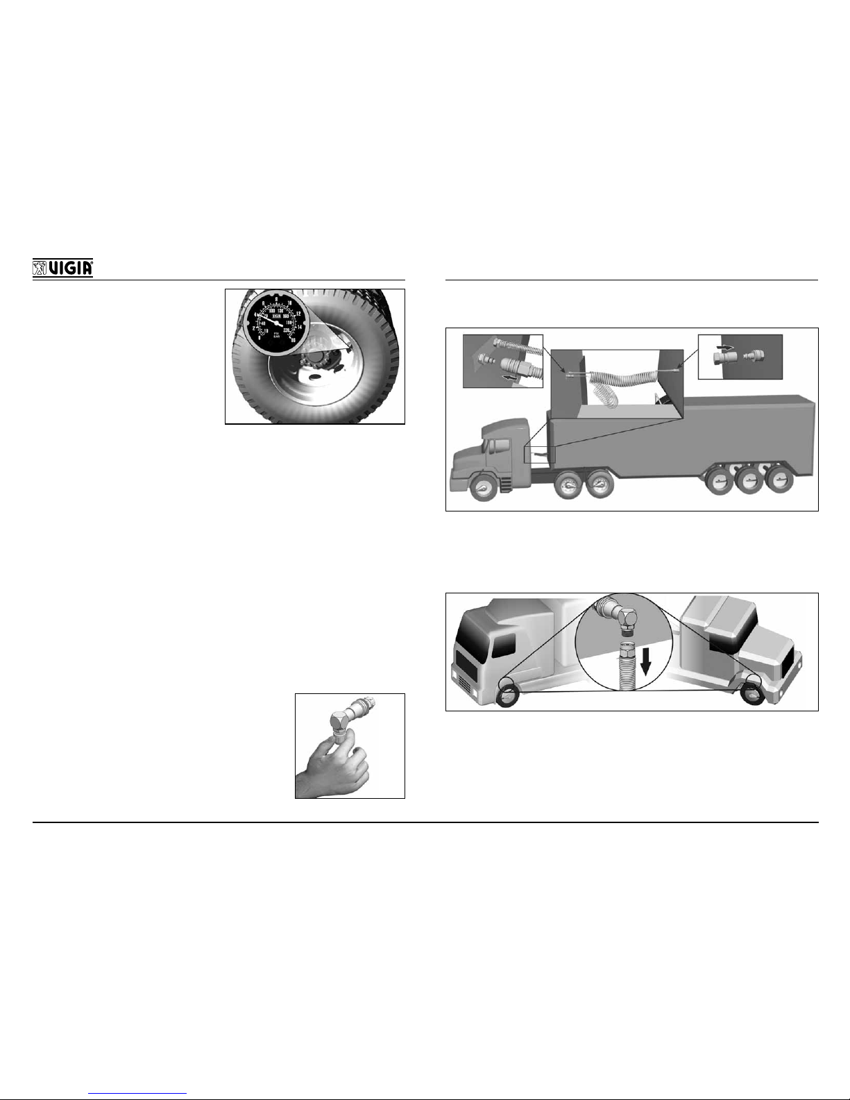
ü Anulación Parcial: En casos de
pérdidas de aire en la conexión
a las llantas anular colocando el
tapón que se provee en el acople
de carrocería. Recurrir al Servicio
Ocial más cercano.
ü Antes de desenganchar desconectar el tubo espiralado.
ü Antes de rebatir la cabina, desconectar los acoples
de carrocería.
Page 23

GARANTIA INGLES
Page 24

Page 25

GARANTIA ESPAÑOL
Page 26

Page 27

ESPAÑA Y PORTUGAL
EURO COLVEN s.a.u.
Carretera N. - IV km. 33.800
Seseña Nuevo 45224 Toledo - España
[email protected]
Tel.:+34 918 936 945
Fax:+34 918 012 803
ESTIJOJE, LATVIJOJE, LIETUVA
UAB AMBER CARGO Ltd.
Parko str. 43 Didzioji Riese
LT-14261 Vilniaus reg.
[email protected]
Tel.: +370 5 2491576
Fax: +370 5 2469663
IRELAND & UNITED KINGDOM
COLDCHAIN Ltd.
Maudlins Ind. Est, Monread Road
Naas, Co. Kildare Irlanda
[email protected]
Tel.: +353 4587 4788
Fax: +353 4587 4835
BULGARIA (България)
VANINA EXPORT JSC
23 Shipka Str.,
Yambol 8600 - Bulgaria
[email protected]
Tel.:+359 88 8528255
Fax:+359 46 663600
FRANCE, BENELUX, POLAND, CZECH Rep.
EBERSPÄCHER
3, rue Blaise Pascal
Zac la Clé Saint-Pierre (78996) Élancourt Cedex
[email protected]
Tel.: +33 130 68 54 54
Fax: +33 130 68 54 55
ITALIA
VIGIA VIESA ITALY s.n.c.
Via G. Rossini, 52
59013 Montemurlo (Prato)
[email protected]
Tel.: +39 0574 650454 r.a.
Fax: +39 0574 652055
DEUTSCHLAND
VIECO GmbH
Zeppelinstrasse 2
76185 Karlsruhe
[email protected]
Tel.: +49 721 9595 720
Fax: +49 721 9595 721
GRECIA (Ελλάδα)
ARION A.G.
Krokeon 18 & Polykratus
10442 Athens - Greece
[email protected]
Tel.: +30 210 5156500
Fax: +30 210 5132110
MANUAL DEL USUARIO NM 343 Y NM 253
CÓDIGO X1430.A198-8
REVISIÓN 001 - VIGENCIA: 30.04.14
COL-VEN S.A. se reserva el derecho, sin previo aviso, de hacer modicaciones en sus productos con el n de mejorar la
calidad, funcionamiento o diseño. COL-VEN S.A. no asume responsabilidad alguna si se realizan cambios en las aplicaciones
o uso de sus productos; tampoco se transere licencia alguna o derechos de patente o marcas por encontrase registradas.
Page 28
 Loading...