

1
Gasifying boiler VIGAS
Gasifying boilers
MANUAL FOR INSTALLATION, ASSEMBLY,
MAINTENANCE AND USE
Warranty Certificate
VIMAR 201
7
Ver.D 2.00
VIGAS and VIGAS
Lambda Control
with AK 4000 control

2
Gasifying boiler Vigas
Content
Declaration of conformity........................................................................................................
1. Technical description........................................................................................................
2. Technical data...................................................................................................................
3. AK 4000 control description...............................................................................................
4. VIGAS boiler - basic configuration.....................................................................................
5. VIGAS boiler - discharge fan confirguration......................................................................
6. VIGAS
Lambda Control
– basic configuration..............................................................................
7. Kotol VIGAS
Lambda Control
- discharge fan configuration.......................................................
8. Temperature setting............................................................................................................
9. Parametres setting...............................................................................................................
10. Time set-up..........................................................................................................................
11. Harware and software information.......................................................................................
12. Error notification...................................................................................................................
13. Configuration setting using PIN 0000...................................................................................
14. Operating instructions...........................................................................................................
15. Boiler maintenance and repairs............................................................................................
16. Boiler accessories and assembly..........................................................................................
17. Service departments.............................................................................................................
18. Problems, cause and solution..............................................................................................
19. Installation instruction............................................................................................................
Electric schema.....................................................................................................................
VIGAS Warranty certificate....................................................................................................
VIGAS Commisssion certificate ............................................................................................
Page
3
4
5
7
9
10
11
13
14
15
16
16
16
17
22
24
26
27
28
30
32
33
33
3
Gasifying boiler VIGAS
DECLARATION OF CONFORMITY
Issued according to § 12 sec. 3 let. a) Act. No. 264/1999 Coll
a 97 / 23 EC
We, Pavel Vigaš - VIMAR,
It is hereby declared that the undermentioned products comply with technical regulations and the products
are safe if predetermined guidelines are followed. All possible measures have been taken to assure the
compliance of products together with technical documentation are within specification and legal
requirementrs. The validity of this statement is void if unauthorized changes are made without permission
of VIMAR.
Product:
Thermal boiler VIGAS a VIGAS
Lambda Control
with AK4000 control
Type:
VIGAS 16, VIGAS 16
Lambda Control
, VIGAS 25, VIGAS 25
Lambda Control
VIGAS 40, VIGAS 40
Lambda Control
, VIGAS 60, VIGAS 60
Lambda Control
VIGAS 80, VIGAS 80
Lambda Control
, VIGAS 100, VIGAS 100
Lambda Control
VIGAS 29 UD
Producer:
Pavel Vigaš - VIMAR
M. Čulena 25, 974 11 Banská Bystrica,
SLOVAKIA
Competent statutory codes (CSC)
CSC no. 576/2002 C.s. – Pressure Equipment Directive (97/23/EC)
CSC no. 308/2004 C.s. – Low voltage electric devices (2006/95/ES)
CSC no. 194/2005 C.s. – Electromagnetic Compatibility Directive (2004/108/EC)
Used harmonized standards for CE marking
STN EN 303-5: 2012; STN EN 60335-1: 2012; STN EN 60335-2-102/A1 : 2010
STN EN 61000-6-3/A1/AC; STN EN 55014-1/A2: 2012; STN EN 61000-3-2/A2: 2010
STN EN 61000-3-3: 20147; STN EN 61000-6-2
Additional data:
Following certificates were used for conformity assessment:
Design Examination Certificate no. 812990017, no.812990016, Certificate no. 00029/104/2/2009,
Certificate no. 812990019, Certificate no. 101299028, Certificate no. 0006/104/2017, Certificate no.
0007/104/2017, Certificate no. 0015/104/2015, Certifikát č. 0003/104/2016, Certifikát č.
0004/104/2016, Certifikát č. 0005/104/2016, Certifikát č. 0006/104/2016.
CE marking was proceed according to § 13, par. 3 letter a) Act. No. 264/1999 Coll.
Issued in:
Banská Bystrica
Name:
VIGAŠ Pavel
Date of issue:
24.04.2017
Title: Owner
Signature:
M. Čulena 25
974 11 Banská Bystrica
SLOVAKIA
VAT no. SK1020548001
REG no. 17956145

4
Gasifying boiler Vigas
1. TECHNICAL DESCRIPTION
VIGAS thermal boilers are designed for the combustion of dry wood materials, using sawdust to wood logs
according to the dimensions of the gasification chamber, with a maximum diameter of 20 cm. Sawdust,
woodchips, splinters and cuttings must be burned in conjunction with wood logs. Thermal boiler VIGAS 29
UD is designed to burn brown coal. It is possible to use dry wooden material as a substitute fuel.
Boilers are welded from 4 – 6 mm steel sheets. Inner boiler sheets, which are in contact with boiler waste
gases, are 6 mm thick, others are made of 4 mm steel.
The heat exchanger is welded from steel pipes, 57x4,5 mm. Exterior boiler panels are made of 0,8 mm
sheet. Thermal insulation of the boiler is made of insulation material, NOBASIL 20 and 50 mm thickness.
Combustion gases pass through the steel boiler neck to the chimney.
The boiler space consists of a combustion chamber, where fuel is dried and gasified. Then accrued gases
pass through the fireproof concrete nozzle or a cast iron nozzle into the combustion chamber, where it
burns with the help of secondary air. Flue gases are intensively cooled in the exchanger. The boiler has
a light up damper controlled by a lever at the front of the boiler.
In order that the boiler complies with the requirements for non-demanding operations, it is equipped with an
AK4000 control located on the top panel of the boiler. The design of the system allows very effective
combustion of various kinds of fuel. The AK4000 Control with graphical display in basic configuration offers
the following:
controlled temperature of heated water ranging from 70 - 85°C (up to 90°C with accu. tank)
continuous and automatic control of the fan according to required output and type of fuel
connnection to and control of discharge fan
connection to and control of circulation pump
connection to the gases thermometer
connection to room thermostat (room temperature regulator is voltage free )
connection to extended regulation (Expander AK 4000) via BH BUS
connection to module AK 4000M data back-up, followed by PC evaluation
graphical schematic indicating hydraulic boiler connection as requested
real time set
Configuration VIGAS
Lambda Control
offers :
control of the servo flap of primary and secondary air, based on data received from the lambda
sensor oxygen level reading.
during a power cut, AA batteries will close the servo-operated flap and this prevents draught from
the chimney burning up the fuel.
The boilers are equipped with a STB thermal fuse, which disconnects the boiler fan if overheating occurs
(above 100°C). A safety mechanism to prevent the boiler from overheating is a requirement of the STN EN
303-5: 2012 standard. It is recommended to install a safety valve TS 131 ¾“ in the exchanger to avoid
overheating.
5
Gasifying boiler VIGAS
2.
TECHNICAL DATA
Chart.1
THERMAL BOILERS
VIGAS
16
16
LC
25
25
LC
40
40
LC
60
60
LC
80
80
LC
100
100
LC
UD 29
Energy efficiency class
A++ A++ A++ A++ A++ A++ A++ A++ - - - - A+
Nominal boiler output kW
16 25 40 60 80 100 29
Boiler class acc. to EN 303-5: 2012
5 5 5 5 5 5 5 5 5 5 5 5
3
Max. operating pressure bar
3
Fuel
Wood, max. moisture 20% of heat value min. 15 MJ/kg
Brown coal
Output capacity kW 8 - 18 8 – 31 14 - 41 15 - 72 25 - 92 25-100 8-35(8-29)*
Fuel consumption with
nominal output
kg/hrs. 4,2 4,1 6,6 6,5 10,5 10,3 16,1 15,7 21,4 20,8 26,7 26,0 7,8 (8,0)*
Alternative fuel
wood waste, wood chips, sawdust, sawdust briquettes,
(for UD 29 also wood, max. moisture 20%)
Chimney draught mBar 0,10–0,20 0,15–0,25
0,20 – 0,30 0,25 – 0,35 0,15 – 0,25
Weight kg 400 430 460 760 930 950 430
Height with control A mm
1135 1385 1420 1120
Height of outlet branch B mm
1075 1310 1400 1045
Height of inlet branch C mm
115 125 215 110
Height of water-feed valve D mm
55 70 135 55
Height of chimney outlet E mm
890 1110 1170 890
Width including lever F mm
645 785 645
Width including panels G mm
590 760 590
Depth H mm 840 1070 1260 1650 1070
Exhaust brand I mm
240 520 240
Diameter of chimney outlet J mm
Ø 160 Ø 196 Ø 160
Depth from edge K mm 188 305 880 1210 218
Spacing of insert L mm
405 70 350
Diameter of inlet brand G
2“
Diameter of outlet brand G
2“
Diameter of water-feed
valve
G
½“ ¾“ ½“
Water volume l
60 75 93 180 205 215 75
Gas temperature:
Nominal output
Minimum output
°C
°C
240
150
Gasification chamber
dimension - Depth
mm 400 570 750 1150 1090 490/440
Height mm
500 750 730 500
Width mm
380 440 575 440
Gasification chamber
dimension (w-h)
mm
435 -255 575 – 318 435 - 255
Max. fuel weight kg
20 35 55 95 150 140 30
Capacity of chamber dm
3
80 120 185 315 483 457 105
Noise level dB
45 45,5 47,7 51,4 54,2 45,5
Max. electric input W
13,8 25,1 21,9 32,9 34,4 45,9 48,8 60,0 62,1 73,2 142,0 153,8
21,9
Voltage/ frequency V/Hz
230ACV / 50 Hz
Pressure loss of water :
∆t 10 0C
∆t 20 0C
mBar
mBar
9,70
1,00
9,75
1,05
10,48
2,55
12,77
3,19
11,83
2,96
11,53
2,84
9,97
1,15
Heat Exchanger
- inlet water temperature
- inlet water pressure
°
C
bar
4 – 15
min 1 – max 4
Safety Drain valve for heat exchanger HONEYWELL TS 131 ¾”
Opening temperature 95 °C
STB fuse, blow temperature 100oC (tolerance: -6 °C - 0
°C
)
Weight flow of gases kg/s
0,034 – 0,047
* specification for wood fuels
6
Gasifying boiler Vigas
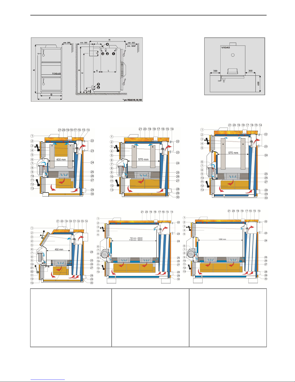
2.1 DIMENSION CHART AND THE POSITION OF SAFETY PLATE TO ENSURE PROTECTION
OF INFLAMMABLE FLOORING
2.2 BOILER SCHEMATICS
KEY:
1. Control AK4000
2. Upper door
3. Chimney flap operating rod
4. Chamber area
5. Primary air conduction
6. Flap for servo Belimo
7. Fan
8. Fan cover
9. Nozzle
10. Secondary air flap
11. Handle
12. Fireclay bricks
13. Bottom door
14. Chimney output
15. Exchanger cover
16. Light up flap
17. Upper back panel
18. Water outlet
19. Thermal fuse
20. Thermometer
21. Upper front panel
22. Lambda sonda
23. Gases thermometer
24. Exchanger pipes
25. Heat proof/concrete filling
26. Secondary air
27. Combustion chamber
28. Gases direction
29. Reverse water leak
30. Filling leak
31. Cleaning flap for 29UD
32. Cleaning slot for 29UD
Sche
ma
tic VIGAS 60,80
Schematic VIGAS 25
Schematic VIGAS 40
Schematic VIGAS 100
Schematic VIGAS 16
Schematic VIGAS 29 UD
Pic. 3
Inlet brand for drain valve
Hole for drown valve insert
Outlet brand of cooling water ¾“
Outlet brand of hot water
Inlet brand of reverse water
Water filling valve
7
Gasifying boiler VIGAS
3. DESCRIPTION OF AK4000 CONTROL
3.1 SAFETY INSTRUCTIONS
Please check the protective cover panels before you plug-in the power lead
Avoid any contact of the power lead with hot parts of the boiler (e.g. smoke flue).
Make sure that upper insulation under the panel remains dry (risk of short circuit if damp)
Do not put any stress on power lead.
Always disconnect the power lead when new electrical components are being connected to the
boiler (eg indoor room thermostat, discharge fan, circulation pump...)
Do not remove the protective cover panels, and particularly the fan cover panel, when the boiler is
in operation.
Check if the voltage displayed on the label is same as your distribution network.
Always keep to the terms of use
3.2 CONNECTION TO THE POWER SUPPLY
AK 4000 Control is an integral part of VIGAS boilers.
The control is connected when the power lead is plugged into a 220/230V power supply. The visual display
with basic image is active when the power lead is plugged-in (pic.4). Servo-flap used in VIGAS
Lambda Control
is set to basic position (pic.5).
3.3 SERVICE CONDITIONS
AK4000 Control is designed for operation within a temperature range from +5°C up to +45°C. The Control
cannot be used in a moist environment or in direct sunlight.
3.4 MAINTENANCE OF AK4000 CONTROL
Keep in a clean and dust free environment. Anti-static cloths or wet wipes are recommended to wipe-off
dust and impurities from metal covers and the control panel.
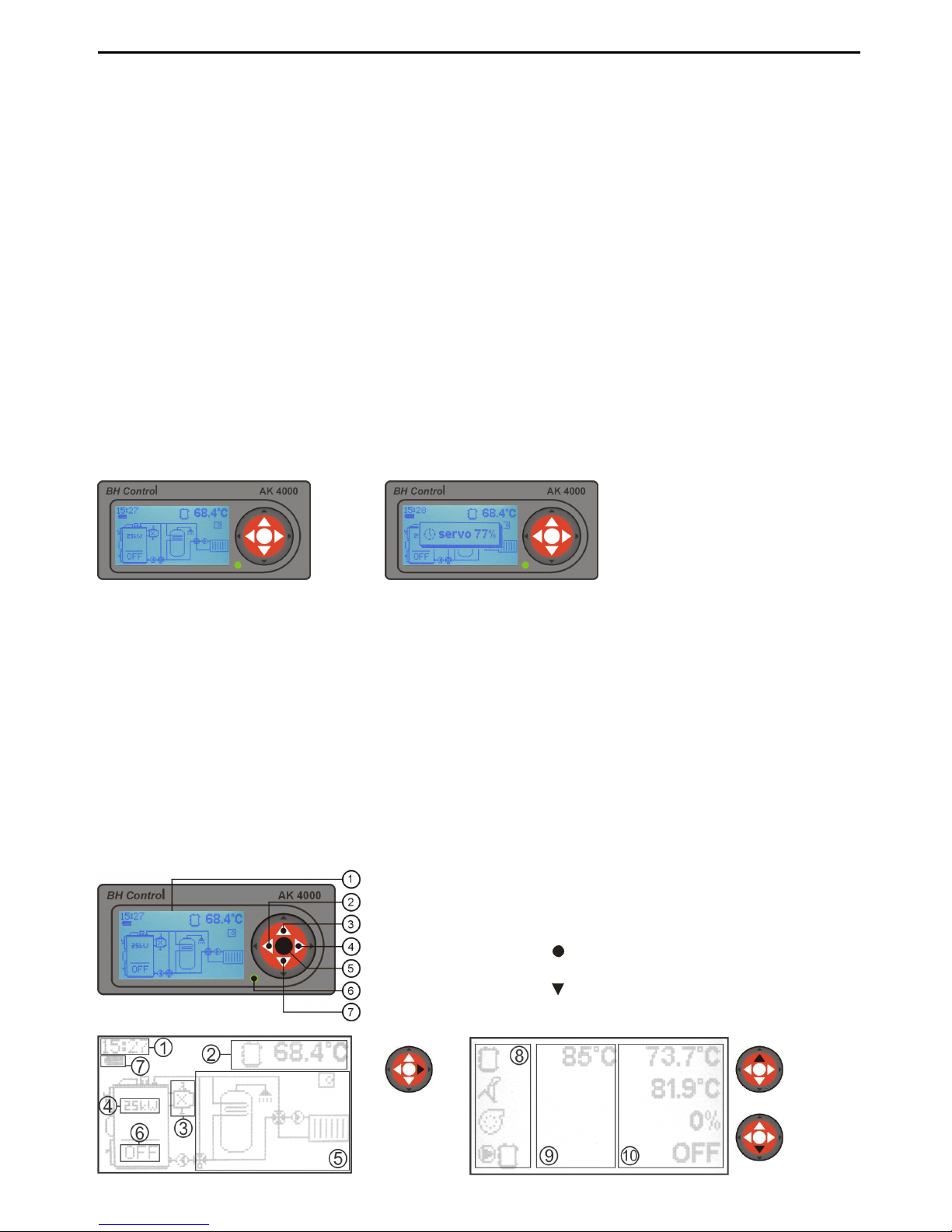
3.5 CONTROL PANEL
Part of the electronic control panel is equipped with buttons, visual display and schematics. Further
information is available in the following sections of this manual.
pic.
6
Pic.5
1. Graphic display 128 x 64 pix.
2. Button ◄ with functions, ENTER
3. Button▲ with functions
4. Button ► with functions, EXIT (ESC)
5. Button (ENTER) with functions
6. LED control (green - OK, red - ERROR)
7. Button switch functions
Pic.4
pic.
7
Graphic information
Coding line information
(chap.13.5)
8
Gasifying boiler Vigas
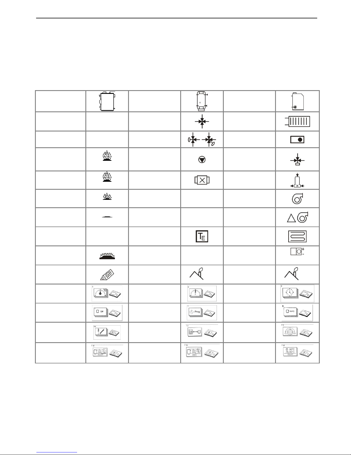
3.6 SYMBOLICS
1. Real time indication
2. Coding line –
indication of current boiler figures
Modification ▲ or
3.
Indication of discharge fan, lambda sensor, gas
thermometer
4.
Indication of nominal output when boiler is
switched off.
Boiler
Accumulator
tank
External boiler
Boiler „ON“ ON DUOMIX
Heating Circuit
Boiler „OFF“ OFF
Valve with
servomotor
Indoor
thermostat
Flame up
ON
Pump
3-way
thermostatic
valve
Burning
73 0C
Discharge fan
LADOMAT
Afterflaming
52 0C
Lambda
λ
Fan
End of burning
END
Thermometer
T
Fan change
output
External
thermometer
Floor heating
Boiler
attenuation
Indication figure
error
x
Servo-flap
position
servo 50%
Add fuel
Shut-down
temperature
end
Max. exhaust
gas figures
max
Temperature
set up
Parameters
set up
Time set up
Error
notifications
Programm
Configuration
data
Servise set ups
Memory modul
Motion
regulation
Schemas
option
Installation data
Indication
option
5.
Graphic indication of hydraulic connection
schematic.
6. Boiler status indication
7.
Battery condition (2 units type AA) used
to
close servo-flap (only VIGAS
Lambda Control)
8. Symbols
9. Set figures
10. Current figures
9
Gasifying boiler VIGAS
4. BASIC CONFIGURATION OF VIGAS BOILER WITHOUT
EXHAUST FAN
The advantage of the exhaust gas thermometer is to control the maximum exhaust gas temperature, and when this is
reached by the boiler, a fan will come into operation to lower the engine RPM. This results in higher boiler efficiency
and lower fuel consumption. If installed with an accumulator tank, the thermometer will shut down the boiler when fuel
is burned down. The water temperature inside the boiler and accumulator tank has no influence on boiler shut down.
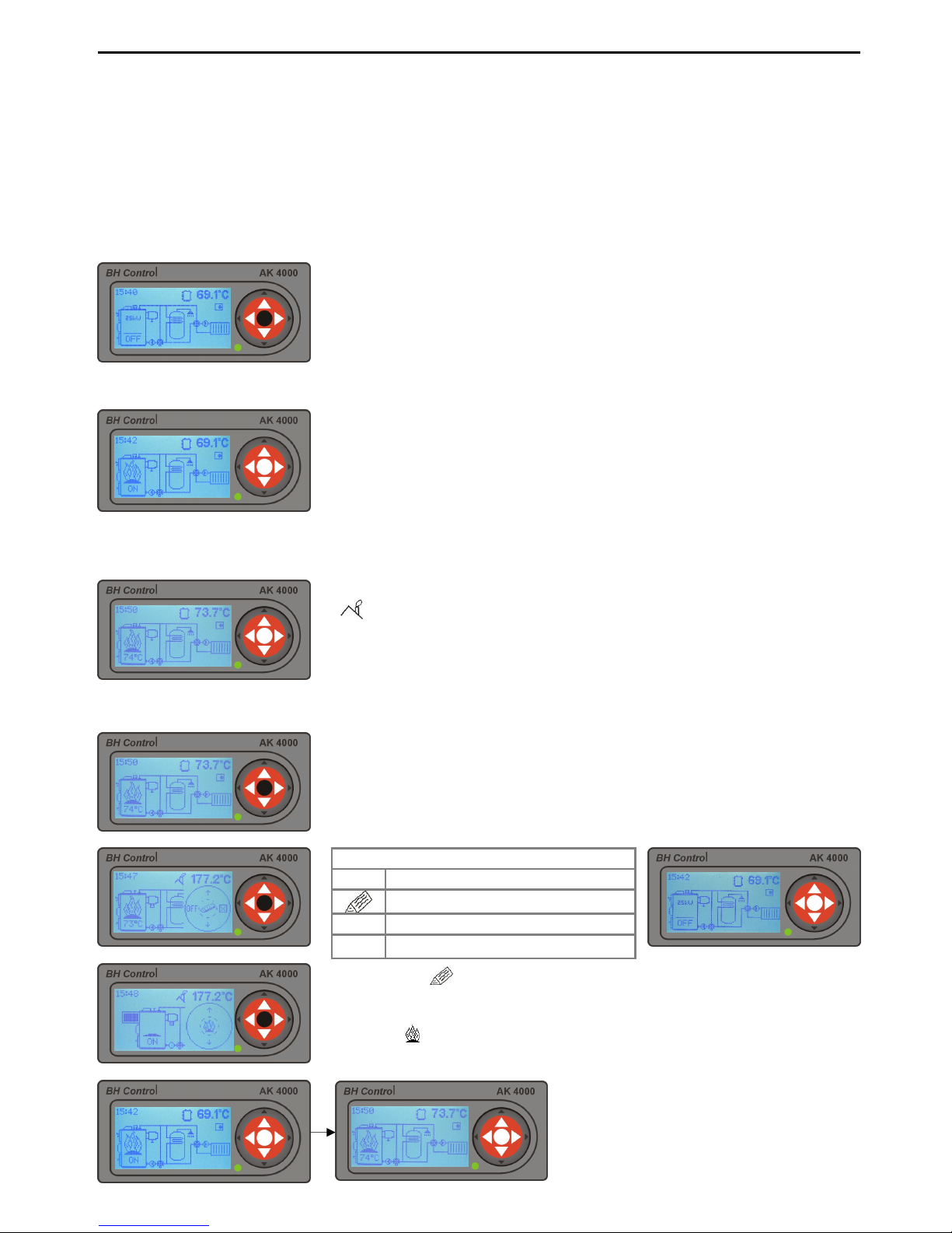
4.1 VIGAS BOILER CONTROL
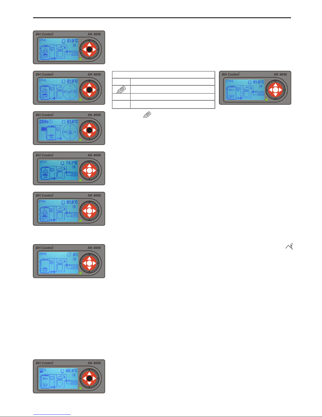
4.1.1 Boiler activation
4.1.2 Boiler active – heating phase, heating regime „On“
4.1.3 Boiler active – burning phase „74°C“
4.1.4 To add fuel or boiler shut-down (manual control)
By pressing „ “ fan will be switched off. Use lever t
o open chimney flap
and consequently open the upper door. Fuel can be added if necessary.
After reloading close the upper door and
chimney flap (pic.12.4).
By
pressing „ “ refuelling will be ended. Fan will switch on automatically.
In the heating phase, the boiler gas exhaust temperature is lower then
the
minimum set-up exhaust gas temperature
. Minimum and maximum
temperatures can be modified in boiler set-
up parameters. Minimum
standard exhaust gas set-up temperature is up 90°C and maximum set
-
up temperature is 220°C.
Boiler can be in heating mode for up to 60
minutes with minimum of 2min. If boiler does not reach bu
rning phase in
this time, it will automatically shut down – sign „END“.
OFF will be displayed when the boiler is switched off. To START the
boiler press middle button ENTER.
The burning phase is active, when the exhaust gas temperature is
(
end) +10 °C or after reaching desired temp. Burning phase is
controlled by PID regulator on the basis of chimney and boiler temp.
If the
temperature rises 1°C above desired temp., the output will be 0
%. If it
decreases >2°C below desired temp., the output will start again.
Choose one option
OFF Switch off
Add boiler
⌧
Cancel display driver
▲
Change indicated figure
Graphic control is used for this operation.
To activate display driver press
middle button „ENTER“. Graphic control offers option to: switch-
off boiler,
add fuel or cancel display driver.
10
Gasifying boiler Vigas
Choose one option
+60 To start discharge fan for 60 secs (use with open burn phase)
ON Switch on
⌧
Cancel display driver
▲
Change indicated figure
Select „+60“ new graphic drive will appear. Running time of discharge
fan is located in the left upper corner of the display.
+60
You can add an extra 60 secs – to a maximum 300 secs
ON
Switch on
0
Discharge fan switched-off
▲
Change indicated figure
4.1.5 Boiler shut-down (automatic)
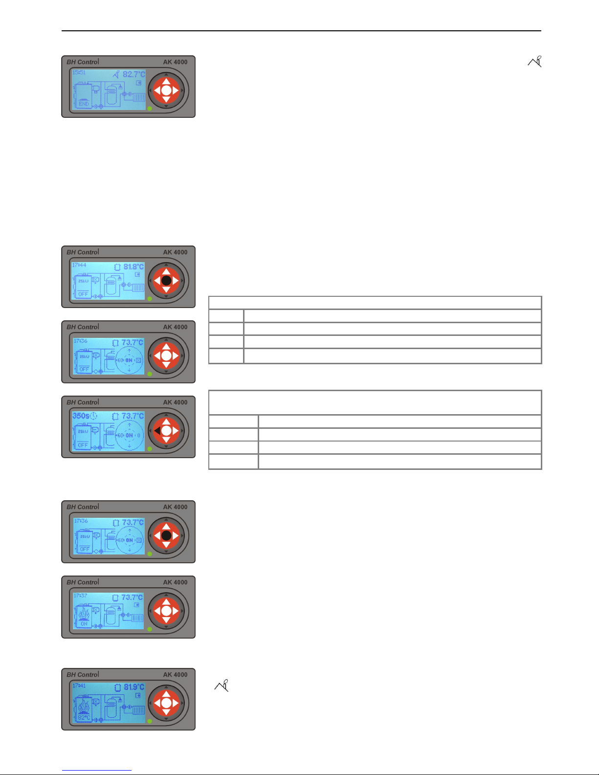
5. VIGAS BOILER CONFIGURED WITH DISCHARGE FAN
(without lambda sensor)
The advantage of a discharge fan installation is increased comfort during boiler open burn and refuelling
stages. The discharge fan helps to significantly reduce flue gas and smoke escape in the surrounding area
during the refuelling stage. The discharge fan helps to quickly start the fire.
5.1 VIGAS BOILER CONTROL
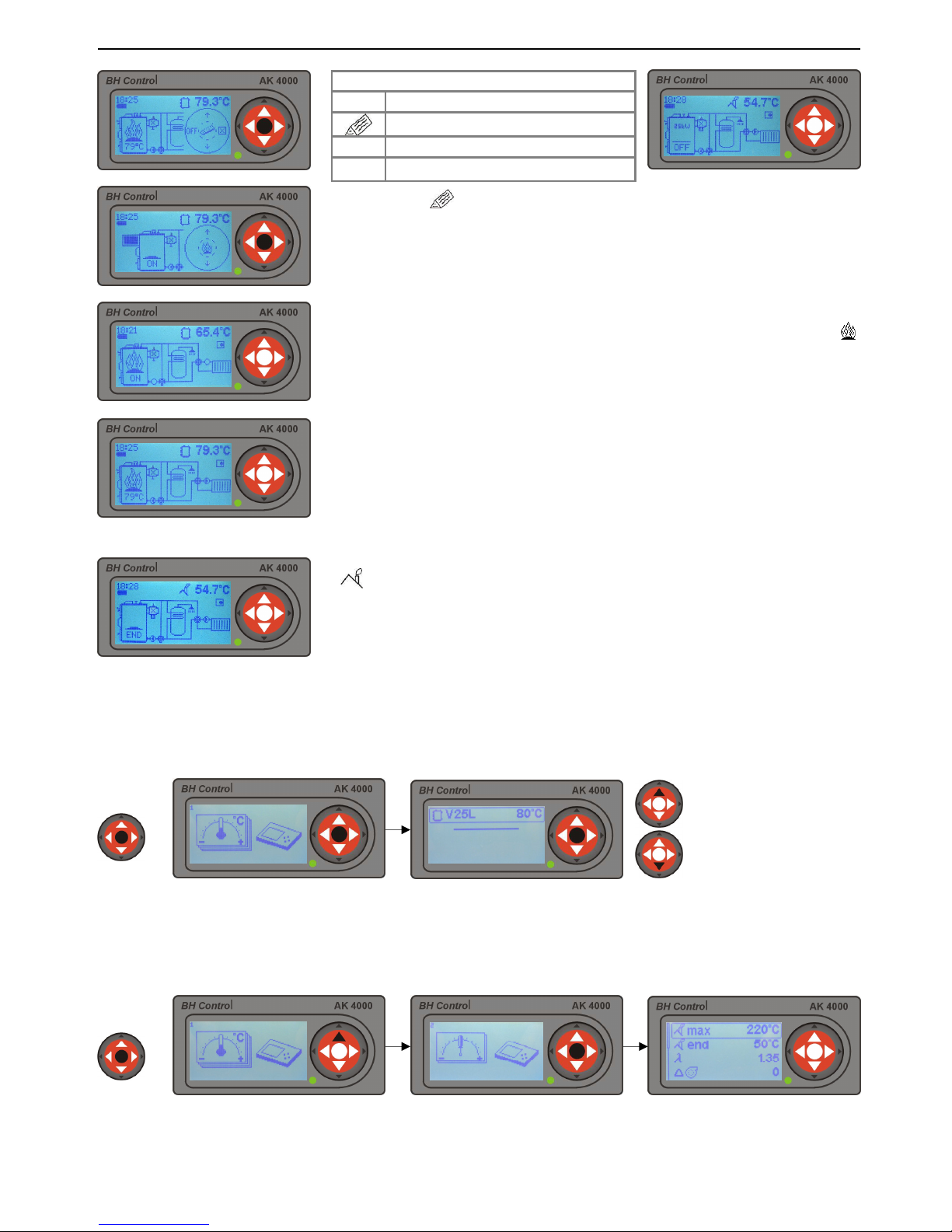
5.1.1 Boiler activation
5.1.2 Boiler active – heating phase „ON“
5.1.3 Boiler active – burning phase „82°C“
When exhaust gas temperature drops under the set-up temperature (
end), the boiler is automatically switched-off. Sign „END“
will be indicated
on the display. By pressing the „ENTER“ button twice the boiler will start
-
up again.
If the boiler is in shut-down phase, with symbo
l „OFF“ on the display, to
start-up press middle „ENTER button.
In the heating phase, the boiler gas exhaust temperature is lower then
the
minimum set-up exhaust gas temperature
. Minimum and maximum
temperatures can be modified in boiler set-
up parameters. Minimum
standard exhaust gas set-up temperature is up 90°C and maximum set-
up
temperature is 220°C.
Boiler can be in heating mode for up to 60 minutes
with minimum of 2min. If boiler does not reach burning phase in this time,
it will automatically shut down – sign „END“.
The burning phase is active, when the exhaust gas temperature is
(
end)
+10 °C or after reaching desired temp. Burning phase is
controlled by PID regulator on the basis of chimney and boiler temp.
If the
temperature rises 1°C above desired temp., the output will be 0
%. If it
decreases >2°C below desired temp., the output will start again.
11
Gasifying boiler VIGAS
5.1.4 Add fuel, boiler shut-down (manual control)
5.1.5 Boiler shut-down (automatic)
6. BOILER VIGAS
Lambda Control
IN BASIC CONFIGURATION
WITHOUT EXHAUST FAN
Boiler VIGAS
Lambda Control
operates using information about the oxygen in the exhaust gas received from
lambda sensor to control the flap of primary and secondary air. This system allows burning of all types of
wood more efficiently and at the same time decrease the fuel consumption by 20-25 %.
6.1 VIGAS
Lambda Control
BOILER CONTROL
6.1.1 Boiler activation
Choose one option
OFF Switch off
Add fuel
⌧
Cancel display driver
▲
Change indicated figure
By pressing „ “ , the boiler fan will be switched-
off and the discharge fan will
be switched-on between 60 secs and maximum 300 secs.
The time is indicated
in the upper left hand corner of the display. By pressing button „+60“
it is
possible to extend discharge fan running time.
Using the lever, open chimney
flap and consequently open the upper door. You can add fuel if
necessary.
After fuel reloading close the upper door and
chimney flap (pic.12.4).
By
pressing
„0“
the discharge fan will be switched off, boiler fan will start working
automatically.
When exhaust gas temperature drops under the set-up temperature (
end), the boiler is automatically switched-off. Sign „END“ will be indicated
on the display. By pressing the „ENTER“ button twice, the boiler will start
operating again.
The graphic control is used for this operation.
To activate display driver
press middle „ENTER“ button. The graphic control offers option to:
switch-off boiler, add fuel or cancel display driver.
If the boiler is in shut-down phase, with symbol „OFF“ on
the display, to
start-up press middle „ENTER“ button.

12
Gasifying boiler Vigas
The servo-controlled flap will move to open
position (servo 100%) when
„ENTER“ button is pressed. Consequently, the following sequence
100%
down to 45% will move the flap to retain the lambda sensor value of
λ
1,35.
When displaying servo at 45%, secondary air is closed. When
displaying 0% primary a
ir is also closed. The flap will move to position
0% only when boiler is in the „OFF“ or „END“ phase.
In the heating phase, the boiler gas exhaust temperature is lower then
the
minimum set-up exhaust gas temperature
. Minimum and maximum
temperatures can be modified in boiler set-
up parameters. Minimum
standard exhaust gas set-up temperature is up 90°C and maximum set
-
up temperature is 220°C.
Boiler can be in heating mode for up to 60
minutes with minimum of 2min. If boiler does not reach burning phase in
this time, it will automatically shut down – sign „END“.
.
6.1.2 Boiler active – heating phase „On“
6.1.3 Boiler active – burning phase
6.1.4 Add fuel, boiler shut-down (manual control)
6.1.5. Boiler shut-down (automatic)
The burning phase is active, when the exhaust gas temperature is
(
end) +10 °C or after reaching desired temp. Burning phase is
controlled by PID regulator on the basis of chimney and boiler temp.
If the
temperature rises 1°C above desired temp., the output will be 0
%. If it
decreases >2°C below desired temp., the output will start again.
Choose one option
OFF Switch off
Add fuel
⌧
Cancel display driver
▲
Change indicated figure
By pressing „ “ the boiler fan is switched off.
Open chimney flap
and
upper door. Add fuel as necessary. After that, close upper door and
chimney flap. By pressing „ “
finishes fuel reloading and the fan will be
switched on. During fuel reloading, the servo-
controlled flap remains in
the same positi
on as it was before adding fuel. When fuel reloading is
complete, the flap moves to the position (servo 100%).
Consequently,
the following sequence 100% down to 45%
will move the flap to retain the
lambda sensor value of λ 1,35. When displaying servo at 4
5%, secondary
air is closed. When displaying 0% primary air is also closed. The flap will
move to position 0% only when boiler is in the „OFF“ or „END“ phase.
When exhaust gas temperature drops under the set-up temperature
( end), the boiler is automatically switched-off. Sign „END“
will be
indicated on the display. By pressing the ENTER“ button twice, the boiler
will start operating again.
The visual graphic control is used for this operation.
To activate the
display driver, press small middle bu
tton ENTER. The graphic control
offers options: switch-off boiler, add fuel or cancel display driver.

13
Gasifying boiler VIGAS
Choose one option
+60 Start-up discharge fan for 60 secs (recommended in the
heating phase)
ON
Switch on
⌧
Cancel display driver
Change indicated figure
Select „+60“ a new graphic drive will be displayed. Running time of
discharge fan is located in the left upper hand corner of the display.
+60
You can add an extra 60 secs to a maximum of 300 secs
ON
Switch on
0
Discharge fan turns-off
▲
Change indicated figure
7. VIGAS
Lambda Control
BOILER CONFIGURED WITH THE
DISCHARGE FAN:
The VIGAS boiler
Lambda Control
operates with information about oxygen overflow in exhaust gas received from
the lambda sensor which controls the flap of primary and secondary air. This system allows buring of all
types of wood more efficiently and at the same time reduces fuel consumption by 20-25 %.
7.1 VIGAS
Lambda Control
BOILER CONTROL:
7.1.1 Boiler activation
7.1.2 Boiler activated – heating phase „ON“
7.1.3 Boiler activated – burning phase „79°C“
7.1.4 Add fuel, boiler shut-down (manual control)
If the boiler is switched-off with symbol „OFF“ on the display, to re-
start,
press the middle button „ENTER“.
By pressing „ON“ button the servo-
controlled flap will move to an open
position (servo 100 %). Consequently, the following sequence
100%
down to 45% will move the flap to retain the lambda sensor value of λ
1,35. When displa
ying servo at 45%, secondary air is closed. When
displaying 0% primary air is also closed. The flap will move to position
0% only when boiler is in the „OFF“ or „END“ phase.
In the heating phase boiler gas exhaust temperature is lower then setup minimum
exhaust gas temperature. Minimum and maximum
temperatures can be modified in boiler set-
up parameters. Minimum
standard exhaust gas temperature set-up is up to 50°C
and maximum
set-up temperature is 220°C. The pump operates in a continuous
wave during o
pen burn, depending on the boiler water temperature.
The burning phase is active, when the exhaust gas temperature is
(
end) +10 °C or after reaching desired temp. Burning phase is
controlled by PID regulator on the basis of chimney and boiler temp. If
the
temperature rises 1°C above desired temp., the output will be 0
%. If it
decreases >2°C below desired temp., the output will start again.
The graphic control is used for this operation.
To activate the display
driver press the middle button ENTER. G
raphic control gives options:
switch-off boiler, add fuel or cancel display driver.
14
Gasifying boiler Vigas
7.1.5.Boiler shut-down (automatic)
8. TEMPERATURE SET-UP
9. SET-UP PARAMETERS:
Choose one option
OFF Switch off
Add fuel
⌧
Cancel display driver
▲
Change indicated figure
By pressing „ “ the boiler fan will be switched-off and the disch
arge fan
will be switched
-on for 300 secs. The time is indicated in the upp
er left
hand corner of the display. By pressing button „+60“ it
is possible to
extend the discharge fan running time. Using the lever,
open chimney
flap and consequently open the upper door.
You can add fuel if
necessary.
When fuel reloading is complete, close the upper door and chimney
flap.
By pressing „0“ the discharge fan will be switched off. By pressing „
“
fuel reloading is ended and the discharge fan automatically switche
s off
and the boiler fan is switched on. During fuel reloading the servo
-
controlled flap remains in the same position as it was before adding fuel .
When fuel refilling is finished, the flap moves to position
(servo 100%).
Consequently, the following sequence 100% down to 45%
will move the
flap to retain the lambda sensor value of λ 1,35.
When displaying servo at
45%, secondary air is closed. When displaying 0% primary air is also
closed. The flap will move to position 0% only when boiler is in the „OFF“
or „END“ phase.
When exhaust gas temperature drops under the set-up temperature
( end) the boiler is switched off automatically. Symbol „END“
will
appear on the display. The servo-controlled flap will move to position
(
servo 0%). In this position pri
mary and secondary air are closed. By
pressing the „ENTER“ button twice, the boiler will start operating again.
By pressing
„ENTER“
button for 2 seconds temperature set-up can be changed in any phase of the
boiler. In the basic configuration of the boiler (without EXPANDER AK4000), it is only possible to set-up
boiler temperature. Temperature scale is between 700C and 850C.
By pressing
„ENTER“
button for 2 seconds set-up parametres can be changed in any boiler operating
phase by pressing ▲ button. Set-up p
arametres depend on the type of boiler and its configuration.
By pressing ▲
choose the required parameter and by pressing „ENTER“ symbol starts flashing. By pressing ▲
choose required parameter and confirm by pressing „ENTER“.
2 sec.
2 sec.

15
Gasifying boiler VIGAS
9.1 MAXIMUM EXHAUST GAS TEMPERATURE SET UP
9.2 EXHAUST GAS TEMPERATURE SET-UP
9.3 LAMBDA VALUE SET-UP
9.4 FAN OUTPUT SET-UP
9.5 FAN MINIMUM OUTPUT SET-UP
9.6 MINIMUM TEMPERATURE IN THE ACCUMULATION TANK SET-UP
9.7 DISCHARGE FAN SPEED SETTING
max
Select maximum exhaust gas temperature, which will result
in reducing fan speed. It is possible to set-up temperature
between 130°C and 320°C. Temperature set-up depends
on quality of fuel and chimney draught. Recommended
value is 220°C.
end
You can set up exhaust gas temperature to automatically
shut down boiler and pump. It is possible to set-up this
temperature between 20°C and 130°C. If the temperature is
too low, the fuel will burn compeletely. If the temperature is
too high, there will be too much ash in ash in exchanger.
By selecting the temperature, it is possible to control the
size of fire base for the next heating phase.
By increasing or decreasing the value can change the
nominal boiler output. It is possible to change the value
from -3 to +3. One degree represents about 10% of boiler
output. During warmer weather it is advised to decrease
this value.
min
Increasing the value will change the minimum fan speed.
Value can be selected between 0% and 70%. After
reaching the selected set-up value the fan will switch off.
on
In case, the boiler is equipped with discharge fan (see
chap.13.1.3), it can be used in permanent mode to increase
chimney effectiveness. It is possible to control speed
between 30% and 100% or complete shut down by „OFF“
symbol. If it is set as percentage, the fan works together
with blower fan.
λ
Lambda value specifies oxygen surplus in the exhaust gas.
Recommended value is 1.35, which is about 6% of O2. It is
possible to set-up this value from 1,2 up to 1,5. By
increasing the value of O2 in the exhaust gas, the boiler and
emmissions will be less efficient.
MinT
Setting the minimum temperature in the accumulation
tank. Setting range 25-
70°C. If the selected hydraulic
diagram of the accu.tank (see 13.4) and the boiler
exceeds the desired tempe
rature by 1 ° C. of the boiler
there is a transition to a state of depression
The
re-
heating up of the boiler starts when the temperature
in the accu.tank drops to a preset value eg. 30°C.

16
Gasifying boiler Vigas
9.8 DISPLAY INTENSITY SET-UP
9.9 DISPLAY CONTRAST SET-UP
9.10 SCROLLING MENU SET-UP
10. TIME SET-UP
11. HARDWARE AND SOFTWARE INFORMATION
12. ERROR NOTIFICATIONS
By pressing „ENTER“ button, values start flashing. Pressing ▲
choose correct time and date. Mon – Monday, Tue – Tuesday, Wed –
Wednesday, Thu – Thursday, Fri – Friday, Sat – Saturday, Sun –
Sunday.
Warning : During an electricity power-cut clock will stop.
To retrieve information setting, press and hold „ENTER“ button at any boiler phase and press button . Confirm by
pressing „ENTER“. Use buttons ▲ to choose module and confirm by pressing „ENTER“. Information about the
module will be indicated on the display.
AK4000D – Display, AK4000S – Power board unit, AK4000L –
Lambda board module.
To recall error notification press and hold „ENTER“ button at any boiler phase and press
button
twice
. By pressing „ENTER“, error with description will be indicated on the display.
Choose display intensity value. Select value between
0 and 100.
Choose display contrast value. Select value between
18 and 34.
Roll
By choosing „
yes“
option on the display (pic.7) will
show actual boiler values - for example: fan speed,
boiler temperature, exhaust gas temperature, etc. By
choosing „no“ option, selection can be made using
buttons ▲.
Set-up time and date when the boiler is first plugged in. Time is indicated in the upper left hand corner of
the display. To retrieve parametre settings press and hold „ENTER“ at any boiler phase and then press
▲ button twice.
2 sec.
2 sec.
2 sec.

17
Gasifying boiler VIGAS
STB
12.1 STB failure
13. SERVICE SETTINGS PIN 0000 PROTECTED
13.1 SERVICE SETTINGS
13.1.1 Boiler type setting
13.1.2 Lambda sensor setting
13.1.3 Exhaust gas thermometer settings
Service settings are passworded. Only a trained service engineer can alter these settings.
PIN 0000
can only be
used to alter settings in unavoidable instances. In service settings, boiler type can be selected together with
accessories and hydraulic connection schematic, etc. To select service settings using password „PIN 0000“
press
and hold „ENTER“ button at anytime, press ▲button and then press and hold button ◄ for 4 seconds.
„PIN 0000“
will apear. Press „ENTER“ button 4 times. Service sett
ing symbol will appear on the display. Press „ENTER“
and by
choosing buttons ▲ select service operation.
No errors = Green LED indicator
Errors = Red LED indicator
Error notifications and solutions are described in chapter 18.“
PROBLEMS, CAUSES AND SOLUTIONS“
„STB“ failure is caused by the boiler over-
heating.
When this happens, the thermal fuse is activated (
see
pic.)
and the fan is disconnected from the power supply.
The boiler is only re- activated if „STB“
is reset manually
only when the boiler temperature is below 60°C.
To
switch on the boiler press „ENTER“ button.
ATTENTION!
The control display unit of the boiler AK4000 is used to operate all types of
VIGAS boilers. It is important that the
symbol displayed is the same as the boiler
type. When the boiler is in „OFF“
phase the visual display shows the type of
boiler which is compliant with its nominal output.
For correct boiler operation
the type of the boiler must always be the same as the
type indicated on the
production label. Always check, in case the AK4000 display is replaced!!!
Choose boiler type. Type of boiler must be identical
with boiler type indicated on the production label.
Marked: V25 - boiler output TVZ – hotair boiler, UD –
wood-coal, DP – wood-pellets, L – Lambda control.
λ
It is possible to de-activate the lambda sensor from operation
if an error occurs. If this happens, it is possible to run the
boiler in standard version until the lambda sensor is
replaced.
yes = boiler with lambda sensor, no = boiler without lambda
sensor
In case of exhaust gas thermometer error, it is possible to
disconnect the thermometer. The boiler will operate without
the thermometer until it is replaced. Exhaust gas
thermometer will not be used, when the boiler is deactivated, use boiler thermometer symbol: yes = boiler with
thermometer, no = boiler without thermometer.
4sec 4x
2 sec.

18
Gasifying boiler Vigas
13.1.4 Discharge fan settings
13.1.5 Boiler thermometer setting
13.1.6 Maximum chimney temperature settings
13.1.7
Minimal temperature setting for boilers with accumulation tank
13.1.8 Frequency power supply set-up
13.1.9 Temperature unit setting
13.1.10 Summer time setting
The discharge fan is an accessory that can be used with
the boiler. After connection to the boiler and in AK4000
control, it is necessary to choose option „yes“.
yes = boiler with discharge fan, no = boiler without
discharge fan.
MaxT
Maximum chimney temperature setting can be selected
between 75°C and 90°C. Highest value is used for boiler
settings with accumulator tank.
Frequency power supply setting is 50 Hz for EU residents
and 60 Hz for USA and Canadian residents. If you are not
aware of power supply frequency, choose AUTO. Incorrect
frequency can cause clock error.
Temper
.
unit
For temperature unit setting °C-Centigrade or FFahrenheit can be selected.
Summer
Allows set-up to automatically change the clock to
summer-time.
T
There is a possibility to set two types of boiler
thermometers
1. Standard: Type KTY
2.
Alternate: Type PT 1000
MinT
Setting the minimum temperature in the accumulation
tank. Setting range 25-70°C. If the selected hydraulic
diagram of the accu.tank (see 13.4) and the boiler
exceeds the desired temperature by 1 ° C. of the boiler
there is a transition to a state of depression The reheating up of the boiler starts when the temperature in the
accu.tank drops to a preset value eg. 40°C.

19
Gasifying boiler VIGAS
13.2 MODULE AK 4000M SETTINGS
13.3 SERVICE CONTROL FUNCTIONS
13.4 HYDRAULIC SCHEME BOILER SETTING
13.4.1 BASIC CONNECTION SCHEMES
config
To load a new configuration (connection schematic).
Mainly used for systems controlled by EXPANDER AK4000E,
where it is possible to load personal connection schematics.
config
Actual configuration back-
up. It is used for boiler monitoring. It is
advised to perform before monitoring.
firmware
To load firmware (boiler operating software).
Erase
To delete information from module AK4000M.
mon
Boiler monitoring -
to file basic information of the boiler into
memory module.
AK4000S
To load firmware into the power board AK4000S.
AK4000L
To load firmware into the lambda power board AK4000.
By changing hydraulic scheme connection will also change the control of the pump o
utput and boiler configuration.
Therefore, it is very important that software settings for the hydraulic schematic is identical with existing boiler
installation in the central heating system. In the basic memory of the control unit are 4 basic schemes and
schemes
intended for operating with the Expander AK4000E.
On demand, it is possible to add Expander schemes via
AK4000M module (pic.8). Updated schemes for Expander AK4000E can be found on www.vigas.eu
obr.
8
When necessary, it is possible to connect AK4000 control to module AK4000M (pic.8). This module allows the
provision of upgrades and back-
up data maintenance of the boiler control unit. The module is equipped with data
to make it possible to connect to BH BUS power board.
In service settings the functions of each boiler‘s components can be checked according to the symbols in
dicated on
the display. By selecting component and
pressing „ENTER“ button the function will be activated. Displayed
components depend on the boiler‘s configuration.
Using ▲
buttons
,
choose required scheme
and press „ENTER“.
Schema 1 for (BS
-
3)
shall be used with accumulator tank. To protect from low-
temperature corosion, a three-
way thermostatic valve ESBE is used (60°C). Pump
shall be connected to power board AK4000.
Contact T3 of power board AK4000S
is used to connect KTY sensor, to monitor tank temperature.
Attention:
It is not possible to connect room thermostat with Schema 1. I tis
recommended to control the room thermostat by pump.
Schema 0 for (basic schema/BS
-
1)
to protect from low-temperature corosion,
a three-way thermostatic valve ESBE is used (60°C). Water regulation for central
heating is secured by 4-way mixing valve with manual control. For boiler heating,
a combined tank is used. Both pumps must be connected to power board
AK4000. Contact T3 of power board AK4000S is used for connection of room
thermostat (see 20/B2 and 16.4.)
2x
3x

20
Gasifying boiler Vigas
13.4.2 CONNECTION SCHEMES WITH EXPANDER AK4000E
Schema 4
is designed for manual control with 4-way valve. For boiler heating,
a combined tank is used. Both pumps must be connected to power board
AK4000. Contact T3 of power board AK4000S is used for connection of room
thermostat (see 20/B2 and 16.4.)
Recommendation: Connection without 3-
way thermostatic valve does not
secure sufficiently water temperature to 60°C. In order to expand the
lifespan of boilers, it is recommended to use Scheme 0.
Schema 2 for
(BS-2
)
Scheme is the same as scheme 0.
To control water
temperature for central heating, the 3-way mixing valve is us
ed, which is operated
manually.
Attention: Combines water tank must be used together with 3-
way mixing
valve.
Schema 3
to protect from low-temperature corosion, a three-way thermostatic
valve ESBE is used (60°C). Pump must be connected to power board AK4000.
Contact T3 of power board AK4000S is used for connection of room thermostat
(see 20/B2 and 16.4.)
Schema 5
used with one heating circuit for floor or radiator. Central heating
temperature can be controlled according to external temperature, room
thermostat or by combi
nation of both. The boiler pump and central heating pump
are controlled separately. Boiler protection against low-
temperature corrosion
provides 4-way valve with servounit.
Use: Expander basic set (code 5001).
Schema 6
with two separate heating circuits controlled by servounit.
Option to
choose floor or radiator heating or combination. Central heating temperature can
be controlled according to external temperature, room thermostat or with
combination of both. The boiler pump and central heating pump work
separately.
Boiler protection against low-temperature corrosion provides 3-
way thermostatic
valve (60°C).
Use: Expander double set (code 5002).
Schema 7 for (Basic scheme expander (BSE 1)
used with one heating circuit
controlled by servounit for floor o
r radiator heating. Heating of domestic water
supply is controlled by pump. Temperature of central heating is controlled by
external temperature, room thermostat or by combination of both. Boiler
protection against low-temperature corrosion provides 4-way mixing valve.
Use: Expander basic set (code 5001)
Expander AK4000E complements the AK4000 boiler control unit. It enables the possibility to control
the central
heating system unit circuits, including regulating the supply water temperature, using different heating sources.
Use
of indoor thermostat and equithermic control (based on external temperature) or in combination, enables control of the
central heating. Expander AK4000E is supplied in sets. According to the particular schematic connection, it i
s
supplied as: basic set (order no. 5001), double set (order no. 5002) and triple set (order no. 5003)
. After verifying the
connection schemes of the Expander, service settings will be supplied with unit settings for the central heating system
and hot water supply. (Detailed description given in EXPANDER AK4000E service guide).
Technical requirements for additional accessories:
(To specify type, pump diameter and servo-unit consult with boiler specialist)!
1.
Pump 230V/50 Hz.
2.
Servo-unit 230V/50 Hz opening period 60–240 secs
3.
Pump to be installed circa 0,5 m after 4-way valve.
4.
Maximum electrical current for one EXPANDER is 3Amps.
5.
Additional thermometer to be installed circa 0,5 m after pump.
6.
External thermometer to be installed on the nothern side of building
7.
Indoor thermostat - free of voltage.
Expander Basic set (order no. 5001)

21
Gasifying boiler VIGAS
13.5 DISPLAY LINE
13.6 AK4000 CONTROL SYSTEM ELECTRICAL CONNECTION - INPUTS AND OUTPUTS
I/O
AK4000S
– connection to power board
T1
Boiler thermometer T1
T2
Exhaust gas thermometer T2
T3
Indoor thermostat T3
T3
Or accu. Thermometer T3
I/O AK4000E1
– connection for Expander 1
1 T2
Thermometer UK1 to T2
1 R3
Pump voltage UK1 to
R3
1 ON R1
Phase servo-unit
„OPEN“ to R1
1 OFF R2
Phase servo-unit
„CLOSE“ on R2
Schema 8
with two separate heating circuits and accumulator tank. Option to
choose floor or radiator heating or combination of both. Temperature of central
heating can be regulated according to external
temperature, room thermostat or
by combination of both. Boiler protection against low-
temperature corrosion
provides 3-way thermostatic valve (60 °C).
Use: Expander double set (code 5002) + 1 x sensor KTY (code 3032).
Riadkové zobrazenie umožňuje prehľadne zobraziť jednotlivé údaje riadiaceho systému AK4000. Tlačidlami ▲
zvoľte požadovaný údaj a potvrďte tlačidlom „ENTER“. Označené údaje budú zobrazené v
riadkových informáciách
(kap.3.5).
The AK4000 control sys
tem enables the display of both input and output according to actual configuration of the boiler
for particular contacts.
2x
Press „ENTER“ button
and using ▲ buttons
choose required module.
Schema 9 for (BSE
-
2)
with one heatin
g circuit of central heating system using
servounit with accumulator tank. Heating of warm domestic water is controlled by
pump. Water temperature can be regulated on the basis of external temperature,
room thermostat or the combination of the two. 3-way t
hermostatic valve (60°C)
secures the protection of boiler against low-temerature corosion.
Use: Expander basic set (code 5001) + 1x tank sensor KTY (code 3032)
Schema 10
is
used with one heating circuit controlled by servounit for floor or
radiator heatin
g. Heating of domestic water supply is controlled by pump.
Temperature of central heating is controlled by external temperature, room
thermostat or by combination of both. Boiler protection against low-
temperature
corrosion provides 4-way mixing valve.
Use: Expander basic set (code 5001)

22
Gasifying boiler Vigas
14. OPERATING INSTRUCTIONS
14.1 Before operation:
14.2 Boiler in operation
14.3 REGULATING
OPERATION AND OUTPUT
14.4
REFILLING THE CHAMBER WITH FUEL
Read and become fully familiar with the operating instructions, manual and the AK4000 electronic control.
Check water pressure in central heating system (max. 3 bar).
Connect electrical components ( example: pump, discharge fan, indoor thermostat, etc..)
Check fireclay brick supports inside the combustion chamber (pic.3)
Check metal panel covers.
Check power supply connection (230V/50 Hz) ,
Prepare a sufficient amount of fuel for the burning and heating phase.
Lower door open
Burning base
1. Connect boiler to power supply network (230V/50Hz) using the power lead.
2. Wait until the visual display basic image is activated:
a) Boiler without lambda sensor - immediately
b) Boiler with lambda sensor – around 30 secs (automatic servo-unit initialization).
3. Refer to points 4–7 and choose the configuration that matches the boiler installation with accessor
ies
to help handling AK4000 control.
4. Set the boiler AK4000 control to deactivated phase "OFF".
5. Fuel heating:
a) using lever, open chimney (pic.3/3),
b) open upper door (pic.3/2) and place paper on the fireproof nozzle (pic.3/9)
, so that a small piece
extends to lower burning chamber (pic.3/25),
cover with woodchips, then place wood cuts on top
and fill-up with solid wood logs,
c) close upper door and open the lower door slightly
(pic.3/13) to achieve fuel heat in the chamber
(pic.3/4), if the boiler is equipped with discharge fan use for quick start.
d) when fire base is created (takes approx. 10-
15 minutes), close the lower door and chimney flap
using the lever.
6. Switch the boiler „ON“. Boiler will start combustion and will control its output automatically up to t
he
required temperature.
7. To refill with fuel follow steps in chap. 4–7.
8. To shut-down the boiler follow instructions in chap. 4–7.
Fuel inside the boiler moves spontaneously towards the fireproof nozzle. Ash falls through the nozzle and
is deposited in the combustion chamber. Boiler output is regulated automatically according to the set-up
temperature of outlet water. If there is a mains power cut over a long period of time or if the automatic
control fails, it is possible to heat as follows (only applicable for central heating systems with gravitation
flow): open chimney flap and open bottom door a little. If this way of heating is used, it is necessary to
check outlet temperature more frequently and to add less fuel. The boiler may easily become overheated,
if the chamber is full.
•
using lever open chimney flap (pic.3/3),
•
press „ “ button on the display (chap. 4–7),
•
open upper door with caution, to allow smoke to disappear,
•
through upper door (pic.3/2) refill with fuel as necessary
•
close upper door (pic.3/2) and chimney flap (pic.3/3),
•
by pressing „ “ button finish fuel refill

23
Gasifying boiler VIGAS
Gasification chamber cleaning
It is necessary to remove tar from the gasification chamber once a week. It is
recommended to burn it off with the upper door
and chimney flap open. If there is
extra ash which did not fall through the nozzle (9)pic.3
into the fireclay combustion
chamber,
this should be removed from time to time. Fuel bunker will be increased to
original size and primary air flow through nozzle will be increased.
14.5 BOILER SERVICING & CLEANING
Wood characteristic table
Wood
Fuel efficiency
[MJ/kg]
20% humidity
Fuel efficiency
[MJ/kg]
25% humidity
Hardness *
weight [kg/m3]
25% humidity
Poplar 12,9 12,3 1 530
Fir 15,9 14,0 1 575
Spurce 15,3 13,1 1 575
Willow 16,9 12,8 1 665
Pine 18,4 13,6 1 680
Alder 16,7 12,9 2 640
Birch 15 13,5 2 780
Maple 15 13,6 4 660
Beech 15,5 12,5 4 865
Ashen 15,7 12,7 4 865
Locust 16,3 12,7 4 930
Oak 15,9 13,2 4,5 840
[kg/m3] = [kg/fm], fm – fullmeter, * (1 very soft...5 very hard)
During optimal wood burning and keeping minimum temperature of the reverse water at 60°C will ensure
that the gasifying chamber and exchanger will only slightly soot. Using damp wood may ca
use steam to
condense on the walls of the combustion chamber, which creates tar on the surface.
ATTENTION
!!!
Use only recommended fuel.
It is advise not to overload the boiler with fuel when in temporary period, boiler tar can be
decresed.
When adding fuel, do not load between the flange and the chimney flap, which can cause inaccurate
flap closure.
It is important to lay fuel properly, so it will not stop the upper door from closing. Forcing the door
closed may damage the door‘s concrete innerwall.
It is recommended that only people over 18 years of age should operate the boiler.
Exchanger cleaning
It is necessary to clean exchanger pipes once a month using the fire rake (round plate).
Recommendation:
If the exchanger is not cleaned regularly it will become clogged with tar. Do not use a
solvent. The boiler must be cleaned
whilst it is hot! Heat boiler to approx 80°C (without fan) through open
upper door and chimney flap. Then close the flap and door. Using gloves, carefully open exchanger
cover. Clean clogged pipes with relevant accessories. After cleaning, close excha
nger cover and let the
boiler burn / gasify for approx. 5 hours at maximum performance, in order to get rid of any remaining tar.
Warning: During cleaning the boiler room must be well ventilated!
Combustion chamber cleaning
It is recommended to sweep out ash and dust that has fallen
and settled in the combustion chamber once every 3-5 days.
Step 1.
Step 2.
Step 3.
Humidity dependence period
( wood cuts)
Fir
SPURCE
Beech
Recommended humidity
20%
OAK
12
14
16
18
20
22
24
2
6
28
30
6
12
18
24
Number of months after cutting
humidity [%]
Gasifying chamber
VIGAS 16,25,40
Gasifying chamber
VIGAS 60,80,100
Combustion
chamber

24
Gasifying boiler Vigas
15. BOILER MAINTENANCE AND REPAIRS
15.1 DOOR SEAL
15.2 CHIMNEY FLAP TIGHTNESS
15.3 Heatproof nozzle
15.4 FLAP & SERVO-UNIT POSITION SET-UP FOR VIGAS BOILER
Lambda Control
The contrac
tor provides regular checks and boiler maintenance. During operation it is important to check
water pressure, door seals, chimney flap tightness, exchanger cover and seal, flue cleanliness
and fan
performance.
WARNING :
Before boiler is shut-down for the
summer season, clean combustion chamber thoroughly, do not leave
any condensed moisture inside and open bottom door and chimney flap.
The boiler door is stabilized in 3 ways –
two rotary pins and a door catch. If the
door does not fit tightly, it i
s also possible to fix it from the hinge side. Slightly
turn hinge to release and turn by hinge screw and then move door in desired
direction. To change gasket 1 points out the place, where gasket is joined.
The heatproof nozzle is a block made of heat-
proof concrete and its use is to to
mix gases with secondary air to ensure efficient burning.
The nozzle is located
on the water cooling rack. The nozzle is surrounded with heat-
proof concrete at
the same height as the nozzle. The life of the nozzle is dependent on
mechanical damage as a
result of fuel loading or stoking the fire. Therefore, the
nozzle is considered as a spare part. Cracks noticed on the nozzle are not a
reason to change the nozzle. It is only necessary to change the nozzle if it is
dropped or is broken. Remove the pieces of the broken nozzle and replace with
a new nozzle ensuring that it is inserted and fits into the opening.
When cleaning exchanger pipes (pic.3/24) make sure that the flap area is clean, as well as the flap itself.
(pic.3/16). Leakage can decrease boiler performance.
Step
1:
unplug line connector from the power supply 230V/50Hz,
Step 2: loosen screw „1“ with spanner,
Step 3: using a spanner turn the axle (which must turn easily!) anti-
clockwise „2“
to maximum position. Visually check the flap
motion through the window „3“.
Step 4: tighten scew „1“
Step 5: plug in power lead to power supply 230V/50Hz.
It is very important that the servo-unit and flap are in the correct positi
on to control primary and secondary
air in the burning process to ensure minimum emissions. To position the servo-
unit and flap follow these
steps:
When the power lead is plugged in, the power supply to the servo-
unit will start automatic initialization,
which is also shown on the display. During this initialization servo
-unit moves.
VIGAS UD
29 boiler cleaning
I
f using brown coal as fuel, cleaning will be the same as a wood burning boiler. Clean fuel bunker with
cleaning flap (12) pic.3 and ash-drawer as follows:
1. Open bottom door (15) pic.3, insert drawer and close the door.
2. Open cleaning flap and upper door (2) pic.5.
3. Use relevant accessory to pile up ash from fuel bunker area into drawer
4. Wait a moment, open bottom door, take out drawer and close the door.
ATTENTION:
Do not leave ash-drawer inside the boiler VIGAS 29 UD during use.

25
Gasifying boiler VIGAS
15.5 SECONDARY AIR FLAPS POSITION SET-UP
15.6 LAMBDA SENSOR AND EXHAUST GAS THERMOMETER
15.7 SECONDARY AIR SYSTEM CLEANING
Secondary airway cleaning
Attention!!!
During cleaning disconnect the boiler from the power supply!
Step 1: Unplug fan and flap servo-unit connectors
Step 2: Under the fan plate romoval (see chap 15.4 for assembly)
Step 3: Vacuum out the secondary air pipes and check if it is clean.
Cleaning the boiler’s pipe airway system is necessary to achieve optimum burning. If sawdust is used as
a
fuel often, the airway must be cleaned at least once in the season. The system is built with primary and
secondary air trunks. The boiler co
nstruction disassembly of parts to enable areas to be cleaned. When
the fan cover is removed (8) pic.3 this allows ccess to the fan. To clean the pipe airway system
take the
following steps:
Step 1.
Step 2. Step 3. Step 4.
Step 5.
secondary
air
primary air
The position o
f the secondary air flaps can considerably affect burning
quality. VIGAS
Lambda Control
boilers control the amount of secondary air
automatically. This option provides optimum conditions for burning of
all wood types. In VIGAS boilers without lambda sensor the
mixture
of primary and secondary air can be adjusted by screws „1“.
Optimum adjustment of secondary air screws „1“ is 2,5 turns
from
factory set. To change or control position follow these steps:
Step 1: loosen the safety bolt nut on screw „1“,
Step 2: drive screw „1“ in towards boiler all the way
Step 3: then, adjust by 2,5 turn (optimum),
Step 4: tighten safety bolt nut.
Boilers without lambda sensor are equipped with a safety flap (above
the fan) „2“ which stops air going through the fa
nin to the boiler when
the fan is stoppped (only chimney draught).
In case the boiler does
not have sufficient output, check the function of this.
TURN
FUEL
0 Not recommended
1 Wet wood
1,5 Wet softwood
2 Dry softwood
2,5 Dry hardwood
2,5 + Very dry hardwood,
small chips
The Lambda sensor and exhaust gas thermometer must
be clean to function properly. When cleaning exchanger
always gently wipe away dust from the lambda sensor „1“
and exhaust gas thermometer „2“.
Important: Thermomether must be
in accurate
position.
Its metal insert must be at the same level as
mettalic sleeve.
(By changing the position of the
thermometer will alter the temperature considerably.)
Connect the lambda sensor and exhaust gas thermometer
to „3“ and „4“ boxes.

26
Gasifying boiler Vigas
Discharge
Hole for sensor.
Drain valve
–
cool water
inlet
16. ACCESSORIES AND ASSEMBLY.
16.1 SAFETY DRAIN VALVE
Cooling safety exchanger use:
Primary airway cleaning
Check primary airway pipes and only clean if necessary. Congestion can occur
when using wet wood or
boiler runs for a long time in low performance.
Type of
primary airway design is different for each boiler model.
Step 4: Dismantle primary air separation panel.
Step 5: Use vacuum and scraper to clean primary leads and check if clean.
Step 6: It is possible to dismantle the vertical primary air lead but only if it is
absolutely necessary. With boilers VIGAS 16, VIGAS 25 a VIGAS 40
side primary air tube, also ( step 6/a, step 6/b).
Note: It is necesary to use silicone heatproof seal, when this action is
repeated.
Step 6./b
Vertical
primary air lead
A cooling safety exchanger with drain valve TS 131
provides boiler protection against overheating during a
power cut. By forced circulation the pump and water flow in
the central heating will shut down. If there is not an option
to have an auto
matic gravity convection or minimum heat
consumption of 5 kW, the boiler may overheat. The drain
valve TS 131 and cooling exchanger will stop the boiler
from overheating.
Assembly of drain valve TS 131:
Screw the drain valve TS 131 into the boiler sock
et „1“ so it
is water tight. The safety exchanger must be water tight.
The second connection „3“ pic., must be connected
to drain
via a tundish. Insert the thermal sensor into ½“ socket, pic.
„2“.
Warning
:
The assembly of the valve and thermal sensor
is
necessary before the
central heating system is filled with
water.
The pressure of cooling water can not be lower than the
pressure of the mains water.
It is advised not to loosen the ¾“ socke
t „2“ pic. This can
cause water leakage. There is an aluminium ring „4“
under the insert „3“ to seal the copper pipe „5“. If there is
a water leak, tighten ¾“ insert „2“.
Operation rule:
The drain valve is regulated by hot water. If the water temperature is 95°C the valve opens.
Water running
from main source
will absorb the temperature from the boiler and prevent it from possible damage and
overheating. This boiler protection system complies with standards STN EN 303-5:2012.
Side
primary air lead
Step 6./a

27
Gasifying boiler VIGAS
16.2 DISCHARGE FAN
16.3 CIRCULATION PUMP AND 3-WAY THERMOSTATIC VALVE ESBE
16.4 INDOOR THERMOSTAT
16.5 COOPERATION OF VIGAS BOILER WITH ACCUMULATION TANK
Boiler type
Min A
Min B
VIGAS 16, VIGAS 18 DPA
VIGAS 25, VIGAS 29 UD
8 m 160 mm
VIGAS 40 8 m 200 mm
VIGAS 60, VIGAS 80, VIGAS 100 12 m 200 mm
Drawing of parametres V25 and V80 at - www.
vigas.eu
The electronic control allows the connection of the pump to the power board unit of the
AK4000S without using an expander, even in basic version. The operation of the pump
depends on the selected hydraulic scheme and boi
ler temperature. The pump operates in
a pulsating cycle or persistent cycle.
Pulsating cycle
allows the pump to go „ON“ or „OFF“ at specific times. The activity ratio
depends on the boiler output temperature. The advantage of this cycle is to protect the
boiler against low-temperature corrosion. Pump activity is indicated by blicking pump icon.
Persistant cycle is used only with a 3-
way thermostatic valve or Ladomat installation. See
chap. 13.4.1.
When the pump is in operation, the symbol will be flashing on the display.
The discharge fan „2“ is
designed to eliminate exhaust gas in the boiler area during
fuel refilling. In case the boiler‘s chimney does not comply with minimum
parametres
„A“ and „B“, it is recomended to install a discharge fan. This should be
installed between the chimney flue and the chimney body.
The condenser „3“
should be attached on the side of the boiler. It is connected to the power board unit
It is possible to order the AK 4000S in two different sizes.
V25 (order no. 0507)
– for VIGAS 16,18DPA, 25, 29 UD.
V80 (order no.
0508) – for VIGAS 40, 60, 80, 100.
By connecting the indoor thermostat to the boiler, maintenance will become easier. It is
necessary to connect the indoor thermostat to the AK4000S power board. Connect to T3
input contact. The switching contact element is voltage free.
If contact T3 is disconnected,
the indoor thermostat „OFF“ sign will be displayed. The blower fan will shut-
down. The
boiler status is indicated by „ “ symbol
. When the indoor thermostat is „ON“ again, the
boiler is activated.
As standard in the boil
ers VIGAS, one load is sufficient for 12 hours of operation which
means that it uses less than 30% of rated output. In view of the life of the boiler it is
preferred that the boiler operates at least at 50% of rated output. If the boiler VIGAS is used
with
ACCU
tank, 100% of rated output is used to achieve the desired boiler temperature. If
there is current requirement for heating, 100% output of the boiler is divided into charging
ACCU tank and heating. In this case, the tank is recharged by the excess out
put of the
boiler. In view of the fact that the boiler and ACCU tank
is hydraulically connected to each
other, the temperature of the ACCU tank
and the boiler rises to the desired temperature of
the boiler together. After exceeding this temperature by 10°C,
boiler goes into the
attenuaton (0% boiler output). In this mode, heating and charging ACCU tank is
managed solely by means of pumps. The great advantage of this system control is that in
the attenuation mode, it is possible at any time to add the f
uel to the boiler, without
overheating of the ACCU tank
, which in practice increases the time between fuel loading.
The automatic re-heating up takes place only after the exhaustion of ACCU tank
at the
selected temperature MinT. ACCU tank minimal temperature
volume can be adjusted
from 20°C to 70°C. After burning out of fuel and decrease of chimne
y temperature to the
boiler set end, the boiler will shut down. In
a combined automatic boiler VIGAS 18 DPA,
after burning out of fuel "wood" boiler will automatically switch to fuel "pellets" and continue
heating another few days.
NOTE: For all hydraulic circuits with ACCU tank, there must be a thermometer for ACCU
tank (code 3032) connected to regulation AK4000 and its location to insert at the top of the
accu. tank.

28
Gasifying boiler Vigas
17. SERVICE DEPARTMENT
It is advised that repairs to the boiler must be carried out by authorised service engineers appointed by the
manufacturer:
Pavel Vigaš - VIMAR, Príboj 796, Slovenská Ľupča, Slovakia.
tel. 00421 48 41 87 022.
tel. 00421 48 41 87 159
email: vimar@vimar.sk, web: www.vigas.eu
18. PROBLEMS, CAUSES AND SOLUTIONS
Probl
em Cause / Solution
During heating season the boiler output is lower
than previous heating period.
Fuel being used is wet.
Clean pipe airway system.
Clean fan air wings.
When chimney flap is closed, boiler does not
perform then smoke appears.
Not enough primary air is getting through. Clean primary pipe
airway system. Check if flap behind the blower is functioning.
Combustion chamber contains unburned wood. Nozzle hole enlarged. Change nozzle. Set up secondary air to
required position : 3 turns of flap back from closed position.
Lower the temperature end. See chap.9.2.
Smoke leaks through door seal after door is
closed.
Door is not tight enough. Adjust the door. Check door is tight.
Remove gasket and place other way round or replace gasket.
Difficulty in opening the chimney flap. Chimney flap is glued by tar. Increase boiler operating
temperature. Use dry fuel. Increase temperature end. See
chap. 9.2.
After upper door and chimney flap is opened,
the boiler room beomes filled with smoke.
Low chimney draught. Chimney diametre must be bigger than
diameter of boiler flue outlet. A discharge fan recommended.
See chap.16.2.
Cracked fireproof/concrete/ filling This is not a defect. Separates combustion chamber from
gasification chamber.
Fan does not turn. It will only start working
when pushed.
Fan condenser is defective . Change condenser.
After heating phase, the boiler shuts down. Incorrect selection of „End“ temperature. See chap.9.2. for
configuration.
Boiler is in shut-down mode, but the fan is still
in operation.
Damaged wires leading to the fan. Zero leading wire is
connected to ground wire
Pump is operating even though the symbol
does not show on the display.
Damaged pump wires. Zero leading wire of pump is connected
to ground wire.
Warning
indications
and n
o
tifications
Cause/ Solution
T max The display shows the statement "MAX" If the boiler temperature
exceeds 93 ° C.
Error notification
Error identification
(MENU 4)
Cause
/ Solution
STB Error
Red control LED indicating
Boiler overheated – when boiler
cools down, reset STB fuse
manually. See12.1.
Lambda control boiler STB error
Red control LED indicating
Boiler overheated – when boiler
cools down, reset STB fuse
Suspended fuse F1A, control
system is conencted from
AK4000PS
Suspended fuse 3,15A
Red control LED indicating
Suspended fuse 3,15A which
joins boiler.
Check pump connection.

29
Gasifying boiler VIGAS
Boiler temperature reading error
Red LED control indicates
Disconnected boiler thermometer
AK4000D T1 KTY
Disconnected thermomenter -
check thermometer
Damaged thermometer -
replacement required
Boiler thermometer in short circuit
AK4000D T1 KTY
Damaged thermometer –
replacement required
Short circuit in connection of
thermometer - revise
Exhaust gas temperature error
Red LED control indicates
Boiler exhaust gas thermometer
disconnected AK4000D T2 KTY
Disconnected chimney
thermometer – check
thermometer
Damaged chimney
thermometer – replacement
required.
Exhaust gas thermometer short
circuit
AK4000D T2 KTY
Damaged chimney
thermometer – replacement
required
Short circuit in connection area
- revise.
Evaluation error of indoor
thermostat
Red LED control indicates
Reading indoor thermostat error
interference from the room
thermostat due to induction of
parallel power lines.
Improper connection of the
thermostat..
See chap. 6.13 By changing
the hydraulic scheme change
function of contact T3
Evaluation error of lambda sensor
Red LED control indicates
Communication error of AK4000L
LAMBDA COM
Damaged AK4000L module.
Evaluation error of lambda sensor
Red LED control indicates
Disconnected A-supply of lambda
sensor
Wire disfunction
Lambda sensor error
Short circuit of A-supply for lambda
sensor
Aborted heating LS
Aborted power line k LS
Baterry status
Red LED control indicates
Discharged batteries
Replace baterries

30
Gasifying boiler Vigas
19. ASSEMBLY REGULATIONS
19.1 ASSEMBLY AND INSTALLATION INSTRUCTION
19.2 ELECTRICAL EQUIPMENT CONTROL AND MAINTENANCE SAFETY REGULATIONS
Boiler assembly and installation must be carried out by authorized technician.
Boiler must be commisioned by authorized trained technician.
Boiler does not require separate solid base.
Minimum temperature of reverse water returning to the boiler shall be 60 0C.
This condition shall
be secured by thermostatic or thermoregulatory valve. Recommended manufacturer is ESBE: T
ype
VTC312 (G1“) up to 40kW boiler, type VTC512 (G6/4“) up to 150kW boiler performance
Boiler room must be permanently ventilated through min. 0,025 m2 slot.
Diameter for inlet and outlet
must be similar.
Boiler must be installed in the basic, usual surrounding in accordance with STN 33 2000-3.
It is advised to follow saftey and health regulations in accordance with current requirements notice
no. 718/2002 Statute.
It is strictly advise to follow required standards regarding flammability level of materia
ls surrounding
the boiler according to standard STN 73 0823:1983/z1 - Flammability degree of building materials.
The boiler operator person must follow relevant regulations and standards, as well as the following rules:
While boiler in service, none of the following actions may be carried out.
• DO NOT uncover the electronics, fan, thermostat.
• DO NO change the fuse.
• DO NOT repair damaged cables or insulation.
Maintenance and repairs to the boiler with uncovered electrical equipment may only be done by
authorized person, according to notice no. 74/1996 Statute.
Before any interference with electrical equipment, it is necessary to unplug and disconnect power cord
.
Connection to power supply is only allowed after all cover panels are mounted back on the boiler.
If any defect of electrical equipment occurs or boiler insulation is damaged, it is advised:
• DO NOT touch any part of the boiler.
• IMMEDIATELY unplug and disconnet the boiler from power supply.
• TO CALL authorized technician in order to remove failure.
Boiler can only be connected to the heating system with relevant thermal output capacity
When using enhanced circulation, central heating system must offer option, in case of a
power cut
(shutdown boiler and pump) to ensure boiler minimum power at 5kW.
This is provided by safety cooling
exchanger together with Honeywell drain valve TS131.
Drain valve Honeywell TS 131 is additional component, it is not part of the boiler.
In case, boiler is installed with accumulator tank, the minimum tank volume is
calculated according
to STN EN 303/5:2012 as follows: Vsp = 15TB x Q
N
(
1 – 0,3QH/Q
min
).
Minimum recommended volumes
of containers for boilers VIGAS 16 VIGAS 18 DPA - 500 L boiler VIGAS 25, VIGAS UD 29 -
800 L.
Boiler VIGAS 40-1000 L. Boiler VIGAS 60-1500 L. Boiler VIGAS 80, VIGAS 100 -
3000 L. Using a
buffer store, extending the life of the boiler.
Vsp – volume of accumulator tank [L] QN – nominal heating power [kW] TB – combustion interval [hours.]
QH – required boiler power - heating area [kW] Q
min
- minimum heating power [kW]
Boiler must be connected to the chimney correctly and shortest way.
Chimney should not be occupied
by any other devices. Chimney venting must be in accordance with STN 734201 and STN 734210.
We do not recommend permanent
connection to the water supply through inlet valve, in order to avoid
increased pressure in the system. Maximu overpressure is 0,3 MPa.
Except basic maintenance, it is strictly forbidden:
To carry out any work on electrical equipment while boiler is plugged in.
To touch defected electrical equipment, mainly damaged wire insulation, etc.
To operate boiler while uncovered.
To operate boiler with any defect on electrical equipment or installation.
To repair damaged electrical parts of the boiler by person other than authorized and appointed by
producer.

31
Gasifying boiler VIGAS
1. Boiler VIGAS
2. Security group
3. Indoor thermostat
4. Pump
5. Water tank
6. Four-way valve
7. Heating circle
8. Expansion tank
9. Safety valve Honeywell TS 131
10. Exhaust fan
11. Thermostatic valve ESBE VTC 312, VTC 512
12. Three-way mixing valve
13. Accumulation tank
M - Servo-motor
T - Thermometer KTY
TE – Thermometer – outside type KTY
TP – Pump thermostat
19.4
Recommended electric
scheme with
AK 4000
+ Expander AK4000 Basic set
.
19.3
Recommended electric scheme with AK4000
BS-1
BS-2
BS-3
BSE-1
BSE-2

32
Gasifying boiler Vigas
20. ELECTRIC SCHEME
ELECTRIC SCHEME
VIGAS VIGAS
LC
16,25,40 29UD kW
60,80,100 kW
16,25,40 kW
60,80,100 kW
No
Description Code
1 AK 4000D Display
4001
2
AK 4001S Power board
4002 – –
2a
AK 4000SL Lambda board
4003 – –
3 Fan
0514 2 2
0516 –
–
3a
Condenser
0515
2 2
4
STB fuse
3029
5 Thermometer type KTY 3026
6 Gas sensortype PT 1000 3027
7 Servo Belimo 3008 – –
8 Lambda sensor 3009 – –
9
Supply RS 25 - 12
4004 – –
10
Accumulator thermometer
type KTY (4m)
3032
11 Discharge fan
0507
–
–
0508
12
Expander AK4000
SET
13
Memory modul AK4000M
4007
14 Indoor thermostat 3030
K1 Connector 3025
K2 Fan wire
3010 – –
3011 – –
K3
Wire set for STB fuse
3015
K4 Thermometer connection modul
3022
– –
3023 – –
K5 Main ground wire 3018
K5a Ground wire for the control cover panel 3019
K6 Communication wire AK40000(4P4C 0,4m) 4006
K7 Lambda sensor connection modul
3024 – –
–
3024 – – –
K8 Wire for servo-unit 3013 – –
K9 Wire set for power supply RS 25 - 12 4005 – –
standard, extra cost, – not available, only for 40, 40LC,
only for 100, 100LC (2psc)
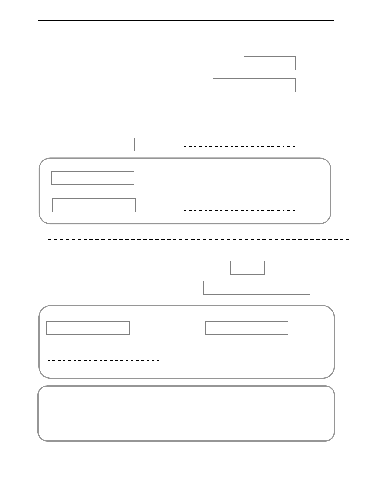
33
Gasifying boiler VIGAS
LETTER OF WARRANTY
Certificate of Quality and Completion
VIGAS commission certificate
Product
Serial number :
The manufacturer confirms that the boiler complies with standards, STN EN 303-5:2012, STN EN 610101+A2:2000, STN EN 50081-1:1995, STN EN 50082-1:2002, STN EN 61000-3-3:2000, STN EN 61000-32:2000+A1+A2:2001.
Production inspection day
Date of purchase
Date of commission
Stamp and signature of seller
Stamp and signature of manufacturer
VIGAS kW
Product VIGAS kW
Serial number
User name and address :
Date of purchase
Date of commission
Signature of heating specialist
Stamp and signature of dealer

34
Gasifying boiler Vigas
Instructions and warranty conditions for customers:
Following operations were performed during commissioning
Boiler maintenance and service explained to customer
Boiler tution before fire
Burning test in the boiler
Confirm and complete data in the warranty document
Owner of the boiler - signature
Warranty does not apply to:
Consumer material: gaskets
, exchanger seal, under fan seal, heatproof nozzle, heatproof
filling, fireclay bricks
Defects caused by customer
Defects caused by incorrect assembly, operation and maintenance, unauthoised handling or
if the product is used for any other purpose than that specified by the manufacturer
To claim warranty the relevant provisions of the civil code.
The manufacturer reserves the right to make changes within the framework of the product innovation
.
Claims regarding the completion of delivery must be in accordance with Commercial Code
and Civil Code of the supplier.
Damage and defects during transporation must be claimed by the customer to the carrier
at
the time of delivery.
Warranty period is 24 month from the date of sale.
The warranty is valid only if the boiler is commissioned by an authorised technician.
The warranty is valid only if the electric equipment i
s connected according to regulation only
by a trained specialist and recorded in relevant documents.
The warranty applies to manufacturer product only.

35
Gasifying boiler VIGAS
Commission Regulation (EU) 2015/1189,implementing Directive 2009/125/EC of the European Parliament and of the Council with regard to
ecodesign requirements for solid fuel boilers, commission Regulation (EU)2015/1189 supplementing Directive 2010/30/EU of the European
Parliament and of the Council with regard to energy labelling of solid fuel boilers.
Product
information
Symbol Jednotka
16 16 LC
25
25 LC
40
40 LC
60
60 LC
Energy efficiency class
A++ A++ A++ A++ A++ A++ A++ A++
Coefficient of energy EEI
128 128 128 129 128 130 126 128
Seasonal Energy efficiency heating area ηs %
87 87 87 88 87 89 86 87
Mode stoking manually
Boiler is recommended to operated from a
reservoir least
L 500 500 800 800
1000 1000 1500 1500
Condensing boiler
No
Combined boiler
No
Preffered fuel Chopped wood ,moisture content 20%
Ch
aracteristic when operating with preffered flue
Useful thermal output at rated power Pn kW
16,0 16,0 25,0 25,0 40,0 40,0 60,0 60,0
Useful efficiency at rated power ηn % 90,9 92,0 91,4 92,6 91,8 92,95 90,59 92,05
Useful thermal output at minimum output /<50% Pp kW 8,0 8,0 8,0 7,6 14,4 14,0 26,2 23,0
Useful efficiency at minimum output ηn % 90,1 90,1 90,6 91,2 90,0 91,67 88,49 90,43
Own electricity consumption at rated power el
max
kW 0,014 0,025 0,022 0,033 0,034 0,045 0,049 0,060
Own electricity at minimum output el
min
kW 0,003 0,014 0,005 0,016 0,005 0,016 0,009 0,020
Own electricity consumption in standby mode PSB kW 0,001 0,001 0,001 0,001 0,001 0,001 0,001 0,001
Season emissions of the heating space TČ1) PM mg/m3 18,4 18,7 15,6 14,0 26,6 21,6 18,0 13,4
Season emissions of the heating space OGC1) OGC mg/m3 28,0 25,9 24,7 14,9 26,3 20,2 22,5 12,2
Season emissions of the heating space CO1) CO mg/m3 535,7 529,5 366,0 323,0 410,5 245,8 444,9 450,9
Season emissions of the heating space NOx1) NOx mg/m3 147,9 149,6 175,6 164,9 169,1 165,8 148,2 145,6
1) Preffer fuel: Chopped wood, moisture content 20%
Electrical Device Connection Record
(pump, discharge fan, indoor thermostat, expander, etc.)
Date
Device
Service person
name
Certificate no.
Service person
signature
Warranty and after warranty repairs Records
Date
Number of repair
protocol
Service person
name
Certificate no.
Service person
signature
Notes
Information sheet
with data on the energy consumption of products
VIGAS

36
Gasifying boiler Vigas
Gasifying boiler VIGAS
MANUFACTURER:
VIMAR Vigaš Pavel
M. Čulena 25
974 11 Banská Bystrica
SLOVAKIA
tel.: 00421 48 4187 022
www.vigas.eu, vimar@vimar.sk
DISTRIBUTOR:
Serial number
Všetky technické zmeny sú vyhradené pre Pavel Vigaš VIMAR 2017, Displej ver.2.00
Obrázky sú ilustratívne a môžu sa líšiť od skutočnosti.
26.4.2017 10:20
 Loading...