

VIGAS 25 Lambda Control, 60, 40, 40 Lambda Control, 16 Lambda Control User Manual
...
1
Gasifying boiler VIGAS
Gasifying boilers
MANUAL FOR INSTALLATION, ASSEMBLY,
MAINTENANCE AND USE
Warranty Certificate
VIMAR 201
7
Ver.D 2.00
VIGAS and VIGAS
Lambda Control
with AK 4000 control

2
Gasifying boiler Vigas
Content
Declaration of conformity........................................................................................................
1. Technical description........................................................................................................
2. Technical data...................................................................................................................
3. AK 4000 control description...............................................................................................
4. VIGAS boiler - basic configuration.....................................................................................
5. VIGAS boiler - discharge fan confirguration......................................................................
6. VIGAS
Lambda Control
– basic configuration..............................................................................
7. Kotol VIGAS
Lambda Control
- discharge fan configuration.......................................................
8. Temperature setting............................................................................................................
9. Parametres setting...............................................................................................................
10. Time set-up..........................................................................................................................
11. Harware and software information.......................................................................................
12. Error notification...................................................................................................................
13. Configuration setting using PIN 0000...................................................................................
14. Operating instructions...........................................................................................................
15. Boiler maintenance and repairs............................................................................................
16. Boiler accessories and assembly..........................................................................................
17. Service departments.............................................................................................................
18. Problems, cause and solution..............................................................................................
19. Installation instruction............................................................................................................
Electric schema.....................................................................................................................
VIGAS Warranty certificate....................................................................................................
VIGAS Commisssion certificate ............................................................................................
Page
3
4
5
7
9
10
11
13
14
15
16
16
16
17
22
24
26
27
28
30
32
33
33
3
Gasifying boiler VIGAS
DECLARATION OF CONFORMITY
Issued according to § 12 sec. 3 let. a) Act. No. 264/1999 Coll
a 97 / 23 EC
We, Pavel Vigaš - VIMAR,
It is hereby declared that the undermentioned products comply with technical regulations and the products
are safe if predetermined guidelines are followed. All possible measures have been taken to assure the
compliance of products together with technical documentation are within specification and legal
requirementrs. The validity of this statement is void if unauthorized changes are made without permission
of VIMAR.
Product:
Thermal boiler VIGAS a VIGAS
Lambda Control
with AK4000 control
Type:
VIGAS 16, VIGAS 16
Lambda Control
, VIGAS 25, VIGAS 25
Lambda Control
VIGAS 40, VIGAS 40
Lambda Control
, VIGAS 60, VIGAS 60
Lambda Control
VIGAS 80, VIGAS 80
Lambda Control
, VIGAS 100, VIGAS 100
Lambda Control
VIGAS 29 UD
Producer:
Pavel Vigaš - VIMAR
M. Čulena 25, 974 11 Banská Bystrica,
SLOVAKIA
Competent statutory codes (CSC)
CSC no. 576/2002 C.s. – Pressure Equipment Directive (97/23/EC)
CSC no. 308/2004 C.s. – Low voltage electric devices (2006/95/ES)
CSC no. 194/2005 C.s. – Electromagnetic Compatibility Directive (2004/108/EC)
Used harmonized standards for CE marking
STN EN 303-5: 2012; STN EN 60335-1: 2012; STN EN 60335-2-102/A1 : 2010
STN EN 61000-6-3/A1/AC; STN EN 55014-1/A2: 2012; STN EN 61000-3-2/A2: 2010
STN EN 61000-3-3: 20147; STN EN 61000-6-2
Additional data:
Following certificates were used for conformity assessment:
Design Examination Certificate no. 812990017, no.812990016, Certificate no. 00029/104/2/2009,
Certificate no. 812990019, Certificate no. 101299028, Certificate no. 0006/104/2017, Certificate no.
0007/104/2017, Certificate no. 0015/104/2015, Certifikát č. 0003/104/2016, Certifikát č.
0004/104/2016, Certifikát č. 0005/104/2016, Certifikát č. 0006/104/2016.
CE marking was proceed according to § 13, par. 3 letter a) Act. No. 264/1999 Coll.
Issued in:
Banská Bystrica
Name:
VIGAŠ Pavel
Date of issue:
24.04.2017
Title: Owner
Signature:
M. Čulena 25
974 11 Banská Bystrica
SLOVAKIA
VAT no. SK1020548001
REG no. 17956145

4
Gasifying boiler Vigas
1. TECHNICAL DESCRIPTION
VIGAS thermal boilers are designed for the combustion of dry wood materials, using sawdust to wood logs
according to the dimensions of the gasification chamber, with a maximum diameter of 20 cm. Sawdust,
woodchips, splinters and cuttings must be burned in conjunction with wood logs. Thermal boiler VIGAS 29
UD is designed to burn brown coal. It is possible to use dry wooden material as a substitute fuel.
Boilers are welded from 4 – 6 mm steel sheets. Inner boiler sheets, which are in contact with boiler waste
gases, are 6 mm thick, others are made of 4 mm steel.
The heat exchanger is welded from steel pipes, 57x4,5 mm. Exterior boiler panels are made of 0,8 mm
sheet. Thermal insulation of the boiler is made of insulation material, NOBASIL 20 and 50 mm thickness.
Combustion gases pass through the steel boiler neck to the chimney.
The boiler space consists of a combustion chamber, where fuel is dried and gasified. Then accrued gases
pass through the fireproof concrete nozzle or a cast iron nozzle into the combustion chamber, where it
burns with the help of secondary air. Flue gases are intensively cooled in the exchanger. The boiler has
a light up damper controlled by a lever at the front of the boiler.
In order that the boiler complies with the requirements for non-demanding operations, it is equipped with an
AK4000 control located on the top panel of the boiler. The design of the system allows very effective
combustion of various kinds of fuel. The AK4000 Control with graphical display in basic configuration offers
the following:
controlled temperature of heated water ranging from 70 - 85°C (up to 90°C with accu. tank)
continuous and automatic control of the fan according to required output and type of fuel
connnection to and control of discharge fan
connection to and control of circulation pump
connection to the gases thermometer
connection to room thermostat (room temperature regulator is voltage free )
connection to extended regulation (Expander AK 4000) via BH BUS
connection to module AK 4000M data back-up, followed by PC evaluation
graphical schematic indicating hydraulic boiler connection as requested
real time set
Configuration VIGAS
Lambda Control
offers :
control of the servo flap of primary and secondary air, based on data received from the lambda
sensor oxygen level reading.
during a power cut, AA batteries will close the servo-operated flap and this prevents draught from
the chimney burning up the fuel.
The boilers are equipped with a STB thermal fuse, which disconnects the boiler fan if overheating occurs
(above 100°C). A safety mechanism to prevent the boiler from overheating is a requirement of the STN EN
303-5: 2012 standard. It is recommended to install a safety valve TS 131 ¾“ in the exchanger to avoid
overheating.
5
Gasifying boiler VIGAS
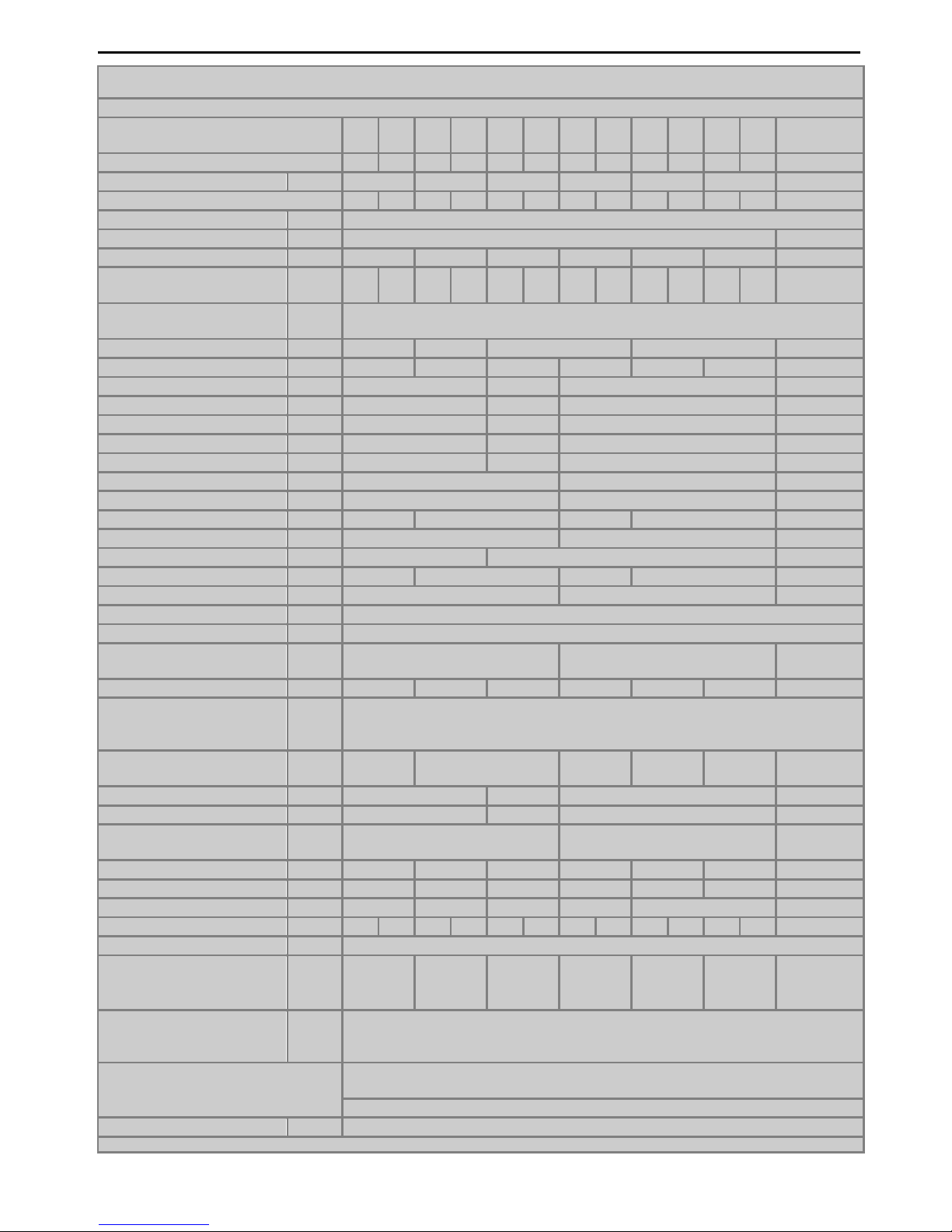
2.
TECHNICAL DATA
Chart.1
THERMAL BOILERS
VIGAS
16
16
LC
25
25
LC
40
40
LC
60
60
LC
80
80
LC
100
100
LC
UD 29
Energy efficiency class
A++ A++ A++ A++ A++ A++ A++ A++ - - - - A+
Nominal boiler output kW
16 25 40 60 80 100 29
Boiler class acc. to EN 303-5: 2012
5 5 5 5 5 5 5 5 5 5 5 5
3
Max. operating pressure bar
3
Fuel
Wood, max. moisture 20% of heat value min. 15 MJ/kg
Brown coal
Output capacity kW 8 - 18 8 – 31 14 - 41 15 - 72 25 - 92 25-100 8-35(8-29)*
Fuel consumption with
nominal output
kg/hrs. 4,2 4,1 6,6 6,5 10,5 10,3 16,1 15,7 21,4 20,8 26,7 26,0 7,8 (8,0)*
Alternative fuel
wood waste, wood chips, sawdust, sawdust briquettes,
(for UD 29 also wood, max. moisture 20%)
Chimney draught mBar 0,10–0,20 0,15–0,25
0,20 – 0,30 0,25 – 0,35 0,15 – 0,25
Weight kg 400 430 460 760 930 950 430
Height with control A mm
1135 1385 1420 1120
Height of outlet branch B mm
1075 1310 1400 1045
Height of inlet branch C mm
115 125 215 110
Height of water-feed valve D mm
55 70 135 55
Height of chimney outlet E mm
890 1110 1170 890
Width including lever F mm
645 785 645
Width including panels G mm
590 760 590
Depth H mm 840 1070 1260 1650 1070
Exhaust brand I mm
240 520 240
Diameter of chimney outlet J mm
Ø 160 Ø 196 Ø 160
Depth from edge K mm 188 305 880 1210 218
Spacing of insert L mm
405 70 350
Diameter of inlet brand G
2“
Diameter of outlet brand G
2“
Diameter of water-feed
valve
G
½“ ¾“ ½“
Water volume l
60 75 93 180 205 215 75
Gas temperature:
Nominal output
Minimum output
°C
°C
240
150
Gasification chamber
dimension - Depth
mm 400 570 750 1150 1090 490/440
Height mm
500 750 730 500
Width mm
380 440 575 440
Gasification chamber
dimension (w-h)
mm
435 -255 575 – 318 435 - 255
Max. fuel weight kg
20 35 55 95 150 140 30
Capacity of chamber dm
3
80 120 185 315 483 457 105
Noise level dB
45 45,5 47,7 51,4 54,2 45,5
Max. electric input W
13,8 25,1 21,9 32,9 34,4 45,9 48,8 60,0 62,1 73,2 142,0 153,8
21,9
Voltage/ frequency V/Hz
230ACV / 50 Hz
Pressure loss of water :
∆t 10 0C
∆t 20 0C
mBar
mBar
9,70
1,00
9,75
1,05
10,48
2,55
12,77
3,19
11,83
2,96
11,53
2,84
9,97
1,15
Heat Exchanger
- inlet water temperature
- inlet water pressure
°
C
bar
4 – 15
min 1 – max 4
Safety Drain valve for heat exchanger HONEYWELL TS 131 ¾”
Opening temperature 95 °C
STB fuse, blow temperature 100oC (tolerance: -6 °C - 0
°C
)
Weight flow of gases kg/s
0,034 – 0,047
* specification for wood fuels
6
Gasifying boiler Vigas
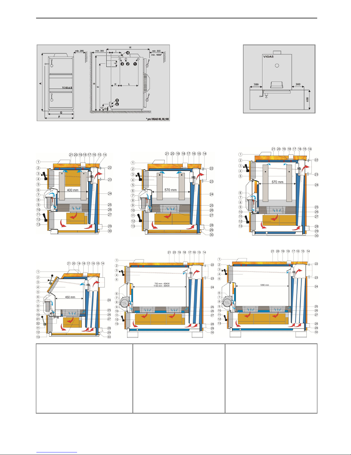
2.1 DIMENSION CHART AND THE POSITION OF SAFETY PLATE TO ENSURE PROTECTION
OF INFLAMMABLE FLOORING
2.2 BOILER SCHEMATICS
KEY:
1. Control AK4000
2. Upper door
3. Chimney flap operating rod
4. Chamber area
5. Primary air conduction
6. Flap for servo Belimo
7. Fan
8. Fan cover
9. Nozzle
10. Secondary air flap
11. Handle
12. Fireclay bricks
13. Bottom door
14. Chimney output
15. Exchanger cover
16. Light up flap
17. Upper back panel
18. Water outlet
19. Thermal fuse
20. Thermometer
21. Upper front panel
22. Lambda sonda
23. Gases thermometer
24. Exchanger pipes
25. Heat proof/concrete filling
26. Secondary air
27. Combustion chamber
28. Gases direction
29. Reverse water leak
30. Filling leak
31. Cleaning flap for 29UD
32. Cleaning slot for 29UD
Sche
ma
tic VIGAS 60,80
Schematic VIGAS 25
Schematic VIGAS 40
Schematic VIGAS 100
Schematic VIGAS 16
Schematic VIGAS 29 UD
Pic. 3
Inlet brand for drain valve
Hole for drown valve insert
Outlet brand of cooling water ¾“
Outlet brand of hot water
Inlet brand of reverse water
Water filling valve
7
Gasifying boiler VIGAS
3. DESCRIPTION OF AK4000 CONTROL
3.1 SAFETY INSTRUCTIONS
Please check the protective cover panels before you plug-in the power lead
Avoid any contact of the power lead with hot parts of the boiler (e.g. smoke flue).
Make sure that upper insulation under the panel remains dry (risk of short circuit if damp)
Do not put any stress on power lead.
Always disconnect the power lead when new electrical components are being connected to the
boiler (eg indoor room thermostat, discharge fan, circulation pump...)
Do not remove the protective cover panels, and particularly the fan cover panel, when the boiler is
in operation.
Check if the voltage displayed on the label is same as your distribution network.
Always keep to the terms of use
3.2 CONNECTION TO THE POWER SUPPLY
AK 4000 Control is an integral part of VIGAS boilers.
The control is connected when the power lead is plugged into a 220/230V power supply. The visual display
with basic image is active when the power lead is plugged-in (pic.4). Servo-flap used in VIGAS
Lambda Control
is set to basic position (pic.5).
3.3 SERVICE CONDITIONS
AK4000 Control is designed for operation within a temperature range from +5°C up to +45°C. The Control
cannot be used in a moist environment or in direct sunlight.
3.4 MAINTENANCE OF AK4000 CONTROL
Keep in a clean and dust free environment. Anti-static cloths or wet wipes are recommended to wipe-off
dust and impurities from metal covers and the control panel.
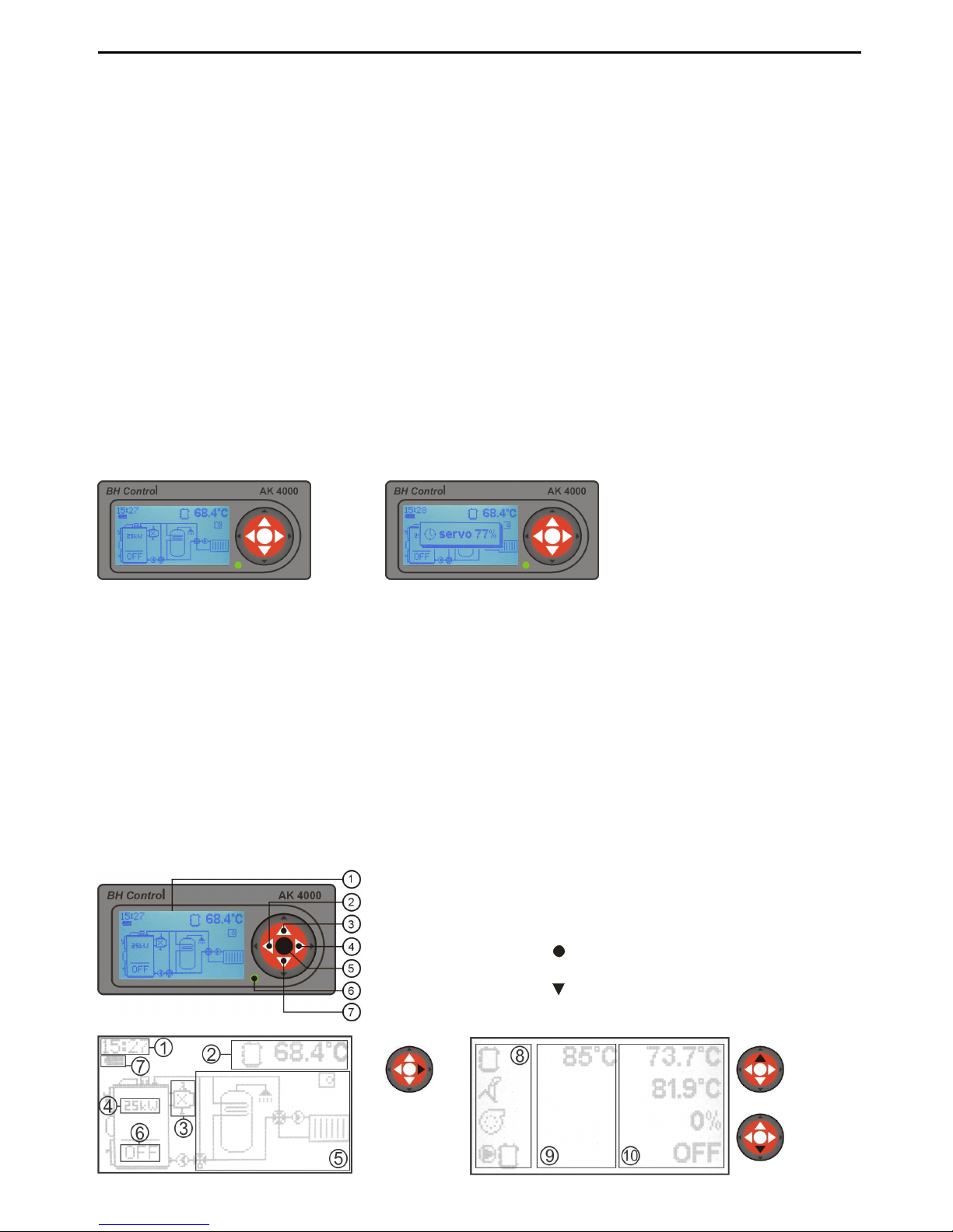
3.5 CONTROL PANEL
Part of the electronic control panel is equipped with buttons, visual display and schematics. Further
information is available in the following sections of this manual.
pic.
6
Pic.5
1. Graphic display 128 x 64 pix.
2. Button ◄ with functions, ENTER
3. Button▲ with functions
4. Button ► with functions, EXIT (ESC)
5. Button (ENTER) with functions
6. LED control (green - OK, red - ERROR)
7. Button switch functions
Pic.4
pic.
7
Graphic information
Coding line information
(chap.13.5)
8
Gasifying boiler Vigas
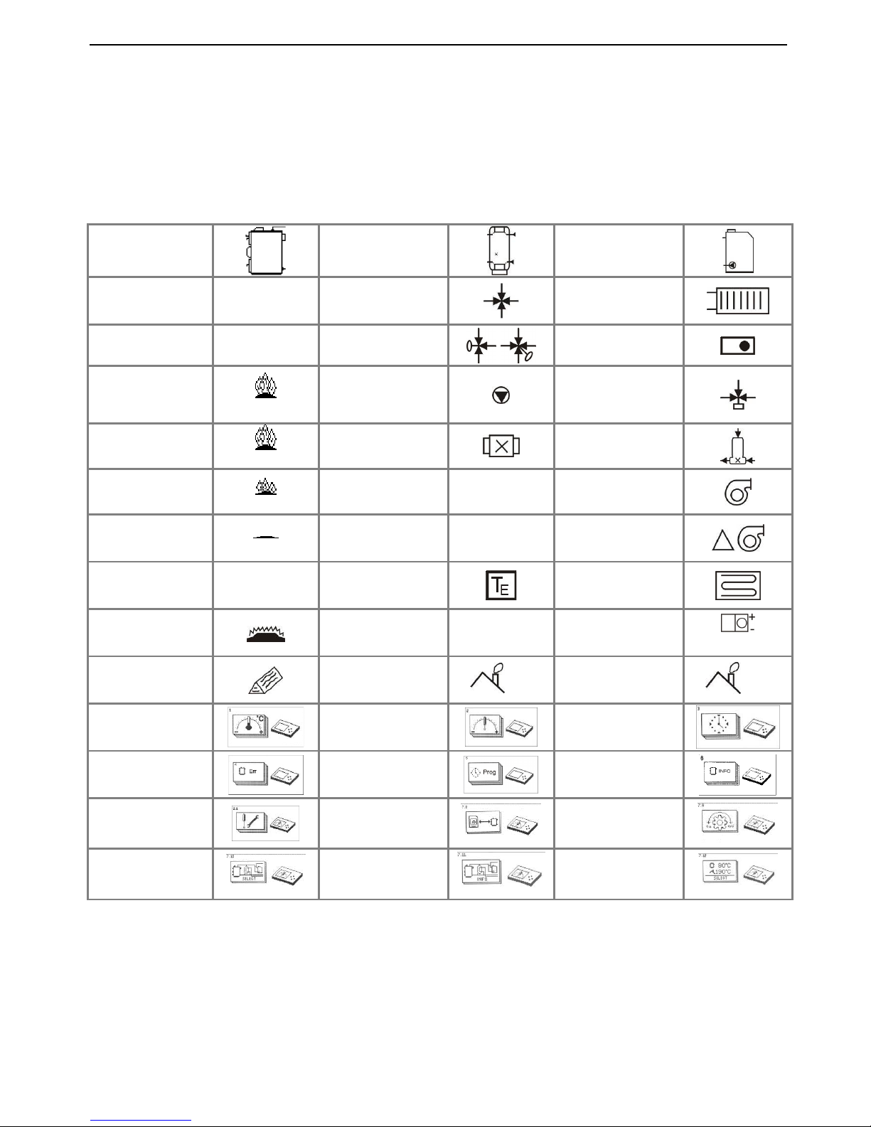
3.6 SYMBOLICS
1. Real time indication
2. Coding line –
indication of current boiler figures
Modification ▲ or
3.
Indication of discharge fan, lambda sensor, gas
thermometer
4.
Indication of nominal output when boiler is
switched off.
Boiler
Accumulator
tank
External boiler
Boiler „ON“ ON DUOMIX
Heating Circuit
Boiler „OFF“ OFF
Valve with
servomotor
Indoor
thermostat
Flame up
ON
Pump
3-way
thermostatic
valve
Burning
73 0C
Discharge fan
LADOMAT
Afterflaming
52 0C
Lambda
λ
Fan
End of burning
END
Thermometer
T
Fan change
output
External
thermometer
Floor heating
Boiler
attenuation
Indication figure
error
x
Servo-flap
position
servo 50%
Add fuel
Shut-down
temperature
end
Max. exhaust
gas figures
max
Temperature
set up
Parameters
set up
Time set up
Error
notifications
Programm
Configuration
data
Servise set ups
Memory modul
Motion
regulation
Schemas
option
Installation data
Indication
option
5.
Graphic indication of hydraulic connection
schematic.
6. Boiler status indication
7.
Battery condition (2 units type AA) used
to
close servo-flap (only VIGAS
Lambda Control)
8. Symbols
9. Set figures
10. Current figures
9
Gasifying boiler VIGAS
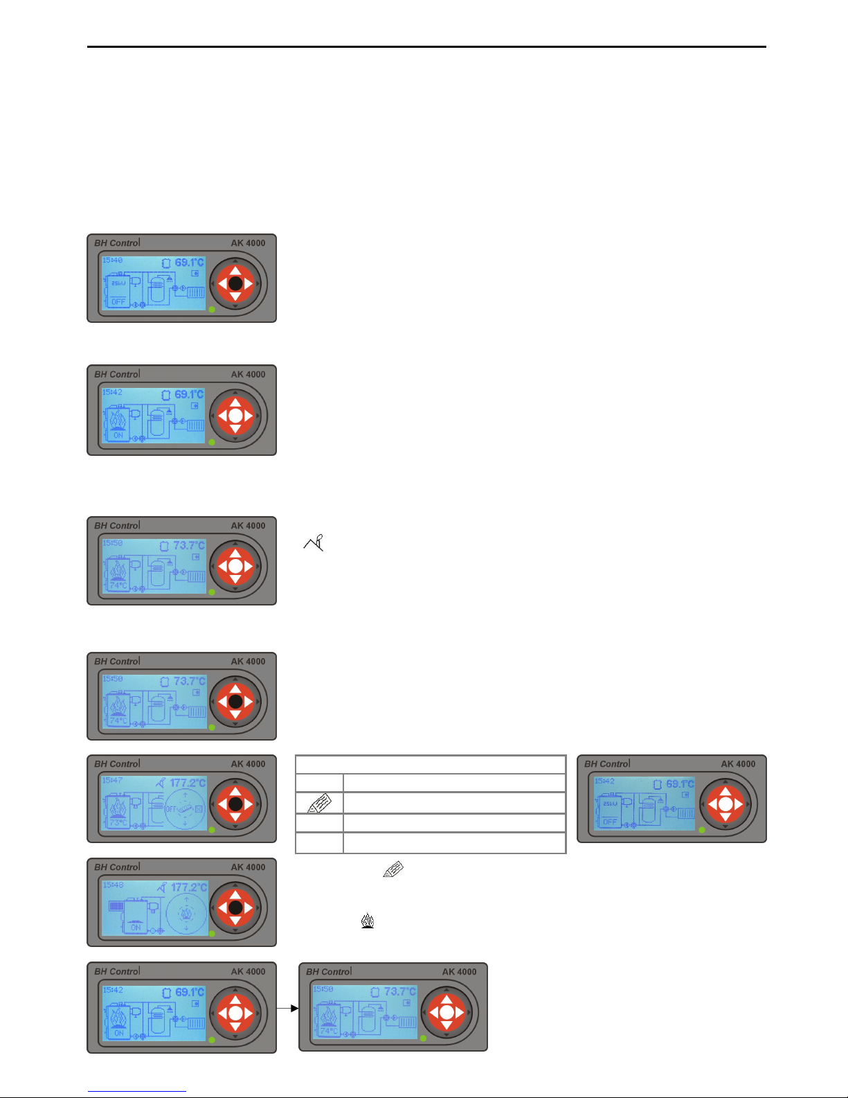
4. BASIC CONFIGURATION OF VIGAS BOILER WITHOUT
EXHAUST FAN
The advantage of the exhaust gas thermometer is to control the maximum exhaust gas temperature, and when this is
reached by the boiler, a fan will come into operation to lower the engine RPM. This results in higher boiler efficiency
and lower fuel consumption. If installed with an accumulator tank, the thermometer will shut down the boiler when fuel
is burned down. The water temperature inside the boiler and accumulator tank has no influence on boiler shut down.
4.1 VIGAS BOILER CONTROL
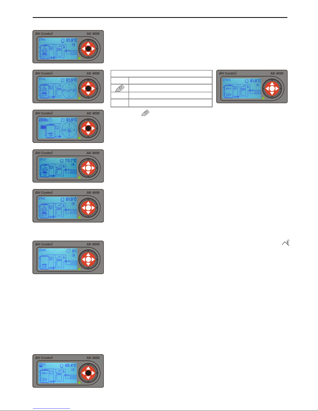
4.1.1 Boiler activation
4.1.2 Boiler active – heating phase, heating regime „On“
4.1.3 Boiler active – burning phase „74°C“
4.1.4 To add fuel or boiler shut-down (manual control)
By pressing „ “ fan will be switched off. Use lever t
o open chimney flap
and consequently open the upper door. Fuel can be added if necessary.
After reloading close the upper door and
chimney flap (pic.12.4).
By
pressing „ “ refuelling will be ended. Fan will switch on automatically.
In the heating phase, the boiler gas exhaust temperature is lower then
the
minimum set-up exhaust gas temperature
. Minimum and maximum
temperatures can be modified in boiler set-
up parameters. Minimum
standard exhaust gas set-up temperature is up 90°C and maximum set
-
up temperature is 220°C.
Boiler can be in heating mode for up to 60
minutes with minimum of 2min. If boiler does not reach bu
rning phase in
this time, it will automatically shut down – sign „END“.
OFF will be displayed when the boiler is switched off. To START the
boiler press middle button ENTER.
The burning phase is active, when the exhaust gas temperature is
(
end) +10 °C or after reaching desired temp. Burning phase is
controlled by PID regulator on the basis of chimney and boiler temp.
If the
temperature rises 1°C above desired temp., the output will be 0
%. If it
decreases >2°C below desired temp., the output will start again.
Choose one option
OFF Switch off
Add boiler
⌧
Cancel display driver
▲
Change indicated figure
Graphic control is used for this operation.
To activate display driver press
middle button „ENTER“. Graphic control offers option to: switch-
off boiler,
add fuel or cancel display driver.
10
Gasifying boiler Vigas
Choose one option
+60 To start discharge fan for 60 secs (use with open burn phase)
ON Switch on
⌧
Cancel display driver
▲
Change indicated figure
Select „+60“ new graphic drive will appear. Running time of discharge
fan is located in the left upper corner of the display.
+60
You can add an extra 60 secs – to a maximum 300 secs
ON
Switch on
0
Discharge fan switched-off
▲
Change indicated figure
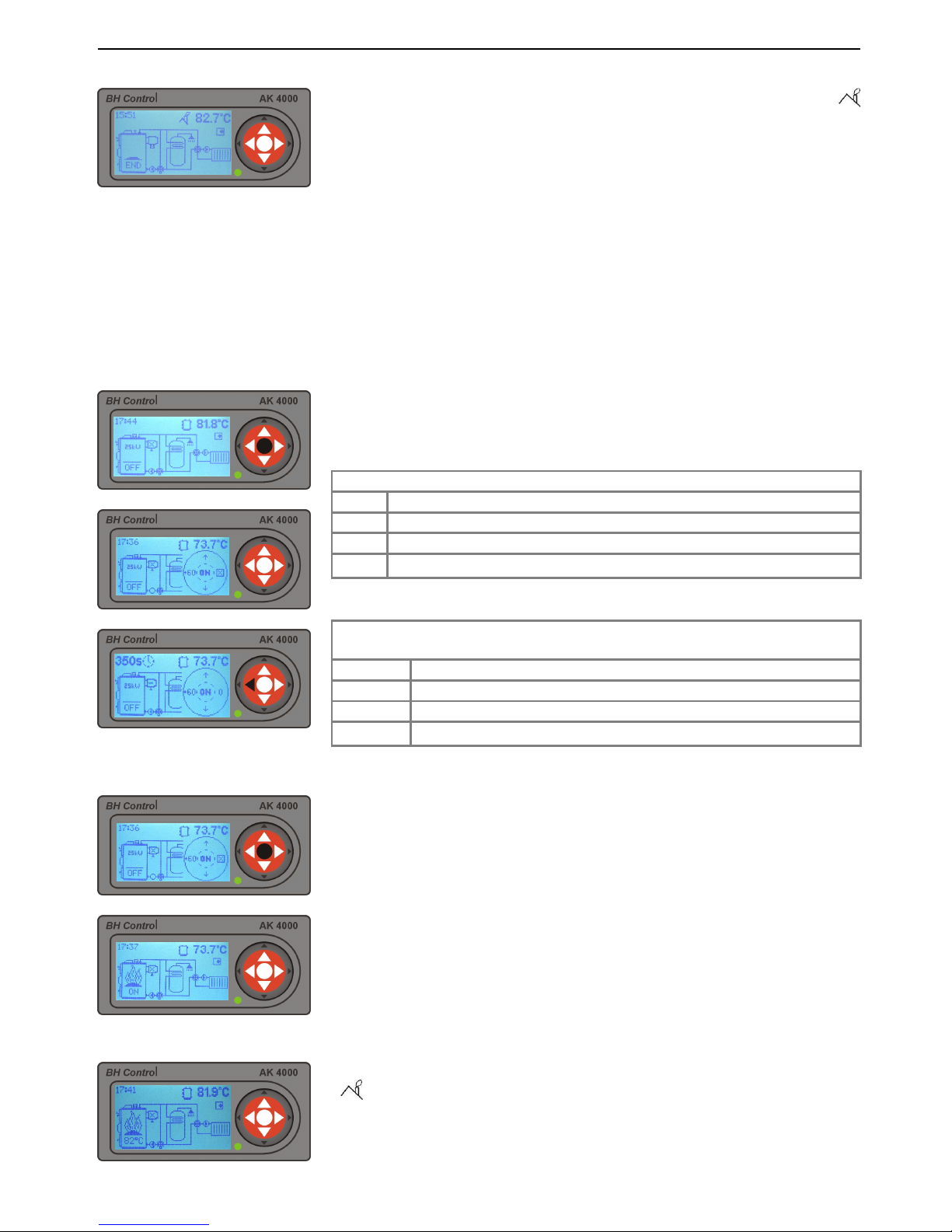
4.1.5 Boiler shut-down (automatic)
5. VIGAS BOILER CONFIGURED WITH DISCHARGE FAN
(without lambda sensor)
The advantage of a discharge fan installation is increased comfort during boiler open burn and refuelling
stages. The discharge fan helps to significantly reduce flue gas and smoke escape in the surrounding area
during the refuelling stage. The discharge fan helps to quickly start the fire.
5.1 VIGAS BOILER CONTROL
5.1.1 Boiler activation
5.1.2 Boiler active – heating phase „ON“
5.1.3 Boiler active – burning phase „82°C“
When exhaust gas temperature drops under the set-up temperature (
end), the boiler is automatically switched-off. Sign „END“
will be indicated
on the display. By pressing the „ENTER“ button twice the boiler will start
-
up again.
If the boiler is in shut-down phase, with symbo
l „OFF“ on the display, to
start-up press middle „ENTER button.
In the heating phase, the boiler gas exhaust temperature is lower then
the
minimum set-up exhaust gas temperature
. Minimum and maximum
temperatures can be modified in boiler set-
up parameters. Minimum
standard exhaust gas set-up temperature is up 90°C and maximum set-
up
temperature is 220°C.
Boiler can be in heating mode for up to 60 minutes
with minimum of 2min. If boiler does not reach burning phase in this time,
it will automatically shut down – sign „END“.
The burning phase is active, when the exhaust gas temperature is
(
end)
+10 °C or after reaching desired temp. Burning phase is
controlled by PID regulator on the basis of chimney and boiler temp.
If the
temperature rises 1°C above desired temp., the output will be 0
%. If it
decreases >2°C below desired temp., the output will start again.
11
Gasifying boiler VIGAS
5.1.4 Add fuel, boiler shut-down (manual control)
5.1.5 Boiler shut-down (automatic)
6. BOILER VIGAS
Lambda Control
IN BASIC CONFIGURATION
WITHOUT EXHAUST FAN
Boiler VIGAS
Lambda Control
operates using information about the oxygen in the exhaust gas received from
lambda sensor to control the flap of primary and secondary air. This system allows burning of all types of
wood more efficiently and at the same time decrease the fuel consumption by 20-25 %.
6.1 VIGAS
Lambda Control
BOILER CONTROL
6.1.1 Boiler activation
Choose one option
OFF Switch off
Add fuel
⌧
Cancel display driver
▲
Change indicated figure
By pressing „ “ , the boiler fan will be switched-
off and the discharge fan will
be switched-on between 60 secs and maximum 300 secs.
The time is indicated
in the upper left hand corner of the display. By pressing button „+60“
it is
possible to extend discharge fan running time.
Using the lever, open chimney
flap and consequently open the upper door. You can add fuel if
necessary.
After fuel reloading close the upper door and
chimney flap (pic.12.4).
By
pressing
„0“
the discharge fan will be switched off, boiler fan will start working
automatically.
When exhaust gas temperature drops under the set-up temperature (
end), the boiler is automatically switched-off. Sign „END“ will be indicated
on the display. By pressing the „ENTER“ button twice, the boiler will start
operating again.
The graphic control is used for this operation.
To activate display driver
press middle „ENTER“ button. The graphic control offers option to:
switch-off boiler, add fuel or cancel display driver.
If the boiler is in shut-down phase, with symbol „OFF“ on
the display, to
start-up press middle „ENTER“ button.
 Loading...