

VIGAS 18 DPA, 26 DPA Manual For Installation, Assembly, Maintenance And Use
1
VIGAS 18 DPA, VIGAS 26 DPA
Gasifying boilers VIGAS
Gasifying boilers
MANUAL FOR INSTALLATION, ASSEMBLY,
MAINTENANCE AND USE
Warranty Certificate
VIMAR 201
7
Ver.D 2.00
VIGAS 18 DPA, VIGAS 26 DPA
with AK4000 control

2
Gasifying boilers VIGAS
VIGAS 18 DPA, VIGAS 26 DPA
Content
Declaration of conformity......................................................................................................
1. Technical description......................................................................................................
2. Technical data.................................................................................................................
3. AK4000 control description.............................................................................................
4. Boiler VIGAS DPA fuel PELLETS ............................................................................
5. Boiler VIGAS DPA fuel WOOD.................................................................................
6. Water outlet temperature setting....................................................................................
7. Time setting....................................................................................................................
8. Hardware and software information................................................................................
9. Error notification..............................................................................................................
10. Configuration set up using PIN 0000..............................................................................
11. Operating instruction.......................................................................................................
12. Boiler maintenance and repairs......................................................................................
13. Boiler accessories and assembly...................................................................................
14. List of servise centers.....................................................................................................
15. Problems, causes and solutions.....................................................................................
16. Installation instructions....................................................................................................
17. Wiring diagram................................................................................................................
Warranty Certificate........................................................................................................
Commissioning Certificate VIGAS DPA ...................................................................
Page
3
4
5
7
9
12
17
18
18
18
19
24
27
29
30
31
33
35
37
37

3
VIGAS 18 DPA, VIGAS 26 DPA
Gasifying boilers VIGAS
EC DECLARATION OF CONFORMITY
Issued according to § 12 sec. 3 let. a) Act No. 264/1999 Statute
and 97 / 23 EC
WE, Pavel Vigaš - VIMAR,
hereby declare on our full responsibility, that reffered products comply with technical requirements,
products are safe if terms of use are followed. We secured all actions, which continuously establish
complaince, provide conformity of referred products with technical documentation within specifications and
legal requirements. If any changes occur on the device without permission of producer, this statement
loses its validdity.
Product:
Warm water boiler VIGAS 18 DPA with AK 4000 control
Type:
VIGAS 18 DPA, VIGAS 26 DPA
Producer:
Pavel Vigaš - VIMAR
M. Čulena 25, 974 11 Banská Bystrica,
SLOVAKIA
Competent statutory codes (CSC)
CSC no. 576/2002 Statute – Pressure equipment Directive (97/23/EC)
CSC no. 308/2004 Statute – Low voltage electric devices (2006/95/ES)
CSC no. 194/2005 Statute – Electromagnetic Compatibility Directive EMC (2004/108/EC)
Used harmonized standards for CE marking
EN 303-5: 2012; EN 60335-1: 2012; EN 60335-2-102/A1 : 2010
EN 61000-6-3/A1/AC; EN 55014-1/A2 : 2012; EN 61000-3-2/A2: 2010
EN 61000-3-3: 2014; EN 61000-6-2
Additional date:
Certificates
Certificate 0023/104/2015 VIGAS 18 DPA
Certificate 0063/104/2016 VIGAS 26 DPA
CE was proceeded according to § 13, sec. 3a) Act no. 264/1999 Statute per amendments.
Issued in: Banská Bystrica Statutory name: VIGAŠ Pavel
Date of issue: 24.4.2017 Title: owner
Signature:
M. Čulena 25
974 11 Banská Bystrica
SLOVAKIA
VAT no.: SK 1020548001

4
Gasifying boilers VIGAS
VIGAS 18 DPA, VIGAS 26 DPA
1. TECHNICAL DESCRIPTION
Combined warm water boiler VIGAS 18DPA and VIGAS 26 DPA offers two different systems of fuel
combustion. Wood fuel combustion provides effective way applied with all Vigas boilers. Pellet fuel heating
is provided by classic burning process on fire grate, made of heat resistant steel, where pellets are
delivered by screw feeder. Boiler VIGAS 18 DPA and VIGAS 26 DPA is designed to burn pellets with
diameter of 6 mm and lenght up to 40mm, as well as dry wood materials from sawdust to wood logs of 52
cm long, with max. diameter 20 cm. Sawdust, woodchips and cuttings are recommended to burn together
with wood logs.
Boilers are welded from 4 and 6 mm steel sheets. Inner boiler sheets, which are in contact with boiler
gases are 6 mm thick, others are made of 4 mm steel. The heat exchanger is welded from 57 x 4,5 mm
steel pipes. External casing of is made of 0,8 mm steel sheets. Heat insulation of the boiler is formed by
20-50 mm mineral wool. The combustion gas is discharged through steel flue gas into the chimney.The
pellet container is designed from 1,5 mm steel sheet and its volume is 250 l.The integral components of the
boiler include: front gear unit, electric ignition unit, security tourniquet, air distributor with servo and fan,
chimney temperature sensor, ultrasound sensor to detect level of pellets. Internal space consists of
combustion chamber, where fuel is dried and combusted. Produced wood gas is carried through nozzle
into combustion chamber, where it burns with support od secondary air.
Pellets are led directly to combustion chamber by accurate dosing from container during combustion with
assistance or regulated air supply. Furthermore, the flue gases are led to double-row heat exchanger,
where intensively cooling down untill reaching the flue gas. Unburned ashes and waste is seated in the
combustion chamber, which is advised to be clean approximately once a week. Boiler offers simple
maintenance due to AK4000 control, located on the top of the boiler.
Control AK4000 offers and permits following actions:
to control heating temperature reached by changing of fan speed using by PID regulator
to control and manage operation of pellet feeeding device
to read water boiler temperature
to read volume of pellets in the container
to read temperature of flue gases
to read motor temperature of pellet feeding device
to connect and control the discharge fan
to connect and control circulation pump
to connect and control room thermostat
to connect extended regulation (Expander AK 4000) via BH BUS
to connect modul AK 4000M for data back-up and possible evaluation via PC
option for graphic view of hydraulic schemas with connection per requirements
SAFETY FEATURES
Boiler is supplied with STB safety, which disconnects the boiler fan to avoid boiler overheating above
100 °C and it is equipped with safety cooling exchanger according to EN 303/5: 2012. Manufacturer
recommends to purchase Honeywell TS131 3/4“ safety valve - to be assembled to the safety cooling
exchanger. The boiler is equipped with a safety cell feeder (tourniquett) driven by chain transmission to
avoid pellet re-ignition inside container. In case of power failure or device error, there is always security air
gap between the container and pellet combustion chamber which prevents ignition of the pellets in the
container. To avoid engine gear damage by possible feeding screw blockage or tourniquet blockage, the
boiler is equipped with a safety thermometer that detects the temperature of the engine and if temperature
is 80 °C, engine will shut down.
5
VIGAS 18 DPA, VIGAS 26 DPA
Gasifying boilers VIGAS
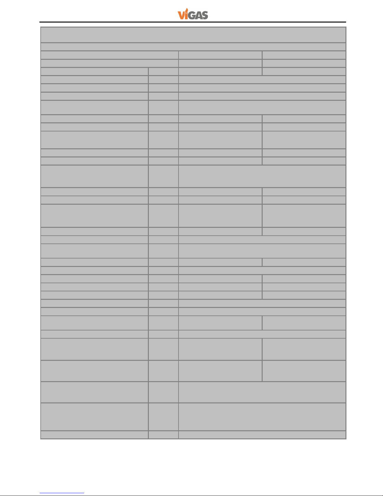
2.
TECHNICAL DATA
Chart 1
Warm water boiler
Combined boiler VIGAS
18
DPA
26 DPA
Energy efficiency class
A++
A++
Nominal boiler output WOOD/PELLETS
kW
24 / 18 36 /
2
6
Boiler class acc. EN 303-5:2012
5
Max. operating pressure
bar
3
Fuel WOOD
Max. wood moisture 20% of heating value. 15 MJ/kg
Fuel PELLETS
Pellets diameter 6 mm, lenght 40 mm (16,5 – 19 MJ/kg)
Standard: ÖNORM M 7135, DIN 51731, EN plus A1
Power range WOOD
kW
8 - 24 15 - 38
Power range PELLETS
kW
1,8 - 18
Fuel consumption with nominal output
WOOD/PELLETS
kg/hrs
6,3 / 4,5 9,5 / 5,5
Chimney draught
mBar
0,15 - 0,20 0,15 – 0,25
Minimum height /chimney diameter
m/mm
8 / Ø160 8 / Ø200
Temperature setting option
Fuel WOOD
Fuel PELLET
°
C
°
C
70 - 85
70 - 85
Weight
kg
480 520
Water volume
l
75 105
Average gases temperature
Nominal power (Wood)/(Pellets)
Minimum power (Wood)/(Pellets)
°
C
°
C
210/160
105/90
260/165
105/100
Wood chamber capacity
l
105 160
Door dimension (w-h)
mm
435 -255
Wood chamber dimension
Depth
mm
520
Height
mm
500 740
Width
mm
380
Max. weight of wood fuel
kg
35 50
Pellet container capacity
l
250 340
Max. weight of pellet fuel
kg
165 225
Noise level
dB
45,5
Max. el. power during ignition
W
1600
Max. el. input during burning
(Wood)/(Pellets)
W
29,9 / 84,9 37,6 / 130,5
Voltage/ frequency
V/Hz
230ACV/50
Pressure water loss :
∆t 10 °C
∆t 20 °C
mBar
mBar
9,97
1,15
10,48
2,55
Burning time at nominal power
Wood
Pellets
hours
hours
6,0
35
4,2
40
Cooling heat exchanger
- water temperature inlet
- water pressure inlet
°
C
bar
4 – 15
min. 1 – max. 4
SAFETY
Drain valve HONEYWELL
TS 131 ¾” Release temperature 95 °C
STB fuse, release temperature 100 °C
(tolerance: -6 °C – 0°C )
Flue gas mass flow
0,034 – 0,047
6
Gasifying boilers VIGAS
VIGAS 18 DPA, VIGAS 26 DPA
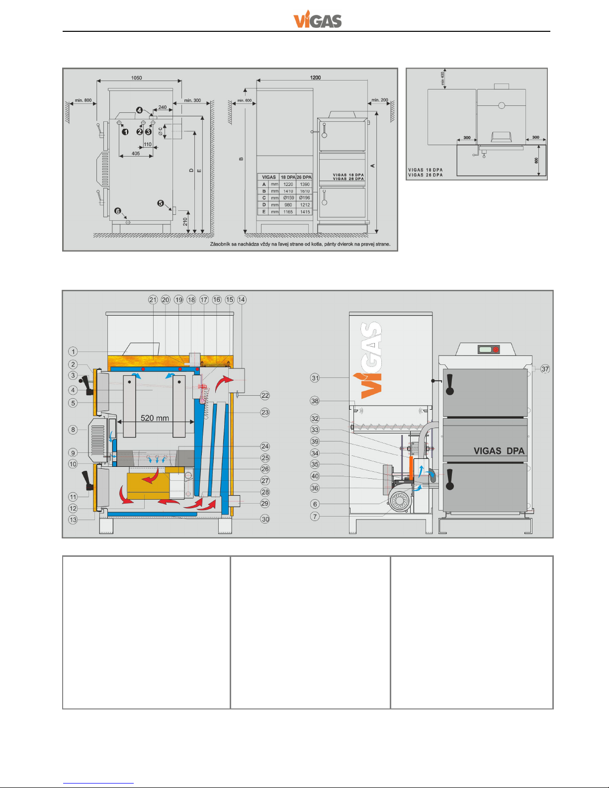
2.1 DIMENSION CHART AND THE POSITION OF SAFETY PLATE TO ENSURE PROTECTION
OF INFLAMMABLE FLOORING
2.2 BOILER SCHEMATICS
DESCRIPTION
1. Control AK 4000
2. Upper door
3. Chimney flap opening rod
4. Wood chamber
5. Primary air supply
6. Shutter
7. Fan
8. Cover panel
9. Nozzle
10. Secondary air shutter
11. Handle
12. Fire clay bricks
13. Bottom door
14. Chimney flue
15. Firing shutter
16. Heat exchanger cover
17. Upper back cover panel
18. Water outlet
19. Fuse STB
20. Temperature sensor
21. Upper front cover panel
22. Gas temperature sensor
23. Heat exchanger pipes
24. Pellet burner
25. Fire proof lining
26. Secondary air
27. Combustion chamber
28. Flue gas direction
29. Return water mounting
30. Water inlet
31. Pellet container
32. Pellet screw feeder
33. Chamber feeder (tourniquet)
34. Driving gear
35. Ignition coil
36. Connection device
37. Safety cooling exchanger
38. Ultrasound pellet sensor
39. Servo-drive
40. Safety temperature sensor
Schema VIGAS DPA
Pic.3
Input insert for valve TS131 ¾“
Opening for immersion pocket ½“
Outlet for cooling water ¾“
Water outlet 2“
Water inlet 2“
Water filling valve ½“
7
VIGAS 18 DPA, VIGAS 26 DPA
Gasifying boilers VIGAS
3. DESCRIPTION OF AK 4000 CONTROL
3.1 Safety instructions
3.2 Connection to power supply
3.3 Operating conditions
3.4 Maintenance of AK 4000 control
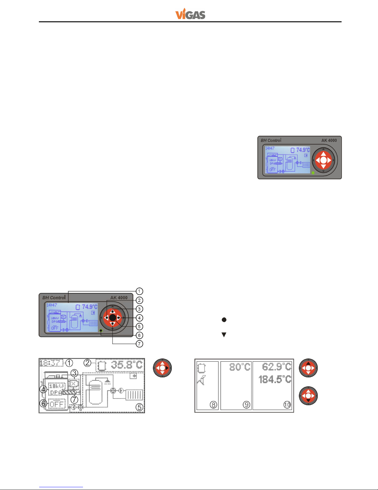
3.5 Control panel
Electronic control panel is equipped with buttons, display including symbols. Further information is
available in the following chapters of the manual. The button options have combined functions,
it depends on provided text and individual boiler configuration setting.
Pic
.6
1. Graphic display 128 x 64 pixels
2. Button ◄ with functions, ENTER
3. Button ▲ with functions,
4. Button ► with functions, EXIT menu (ESC) ,
5. Button (ENTER) with functions,
6. LED light (green OK, red ERROR),
7. Button with functions.
1. Real time image.
2. Information line - current boiler figures shown
Change ▲ or .
3. Information about discharge fan and gas
sensor .
4. Information about nominal power, when boiler
is off.
Pic
.7
Grap
hic information
Line information
(chap.10.5)
5. Graphic information about hydraulic schema
6. Boiler status information.
7. Pellet feeder information.
8. Symbols
9. Set figures
10. Currrent figures
Control AK 4000 presents integral part of VIGAS boilers.
The control will be
connected when power cord is plugged into a
220/230V power supply.The
display is active when power cord is plugged-in (Pic.4).
Before you plug-in the power cord, please check all protective cover panels.
Avoid any contact of power cord with hot parts of the boiler (e.g. gas flue)
Make sure that upper insulation under the cover panel remains dry (risk of short circuit if damp)
Do not use any violent tow on the power cord.
Always disconnect the power cord, when new electrical devices are being installed to the boiler
(e.g. room thermostat, discharge fan, circulation pump).
Do not remove protective cover panels, in particular the fan cover, when boiler in servise.
Check, whether voltage on the label is the same as your distribution network.
Always follow safety operation manual.
Control AK 4000 is designed for operation with area temperature between +5 and +45 °C.
The control
cannot be used in moist environment or in direct sunlight.
Keep in clean and dust free environment. Anti-
static cloth or wet wipes are recommended to remove dust
or impurities from metal cover or control panel.
Pic.4
8
Gasifying boilers VIGAS
VIGAS 18 DPA, VIGAS 26 DPA
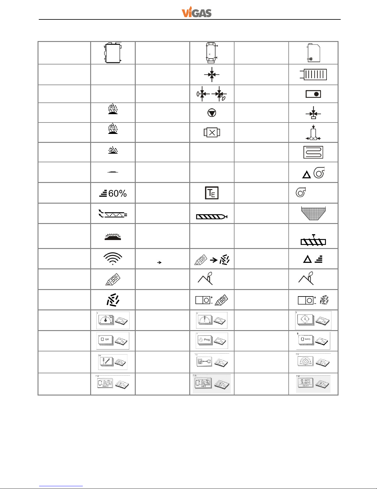
3.6 LIST OF SYMBOLS
Boiler
Accumulator
tank
External boiler
Boiler
switched on
ON DUOMIX
Heating circuit
Boiler
switched off
OFF
Valve with
servodrive
Room
thermostat
Start fire
ON
Pump
3-way thermo
valve
Burning
73 °C
Discharge fan
LADOMAT
Burn out
52 °C
Lambda sonda
λ
Floor heating
End of burning
END
Thermometer
T
Fan perform.
modification
Boiler power
PELLETS
External
thermometer
Boiler power
WOOD
45%
Ignition mode
Screw feeder
Pellet volume
indicator
Room
thermostat
decay
Indication
figure error
x
Temperature of
feeder device
Ultrasound
pellet sensor
Fuel change
Wood Pellets
Boiler power
change
Fuel WOOD
Minimum gas
value
end
Maximum gas
value
max
Fuel PELLETS
Servo position
fuel WOOD
Servo position
fuel PELLET
Temperature
setting
Parameters
setting
Time setting
Error
notifications
Programm
Configuration
data
Service
settings
Memory modul
Motion control
Schema
options
Installation
data
View option
9
VIGAS 18 DPA, VIGAS 26 DPA
Gasifying boilers VIGAS
Boiler VIGAS 18 DPA offeres possibility, that during fuel change from pellets to wood or wood to pellets, it is
not necessary to perform any technical modif
ications on the boiler body. It is only required to choose type of
fuel on the display of AK 4000 control. After selecting the fuel type, servomotor driven shutter will
automatically move to desired position (pic.3/6). Boiler design and air control enables
automatic transition of
fuel from „WOOD“ to „PELLETS“, after „WOOD“ fuel has burned out.
4. Boiler VIGAS 18 DPA fuel PELLET
Quick choice selection of fuel type using round button
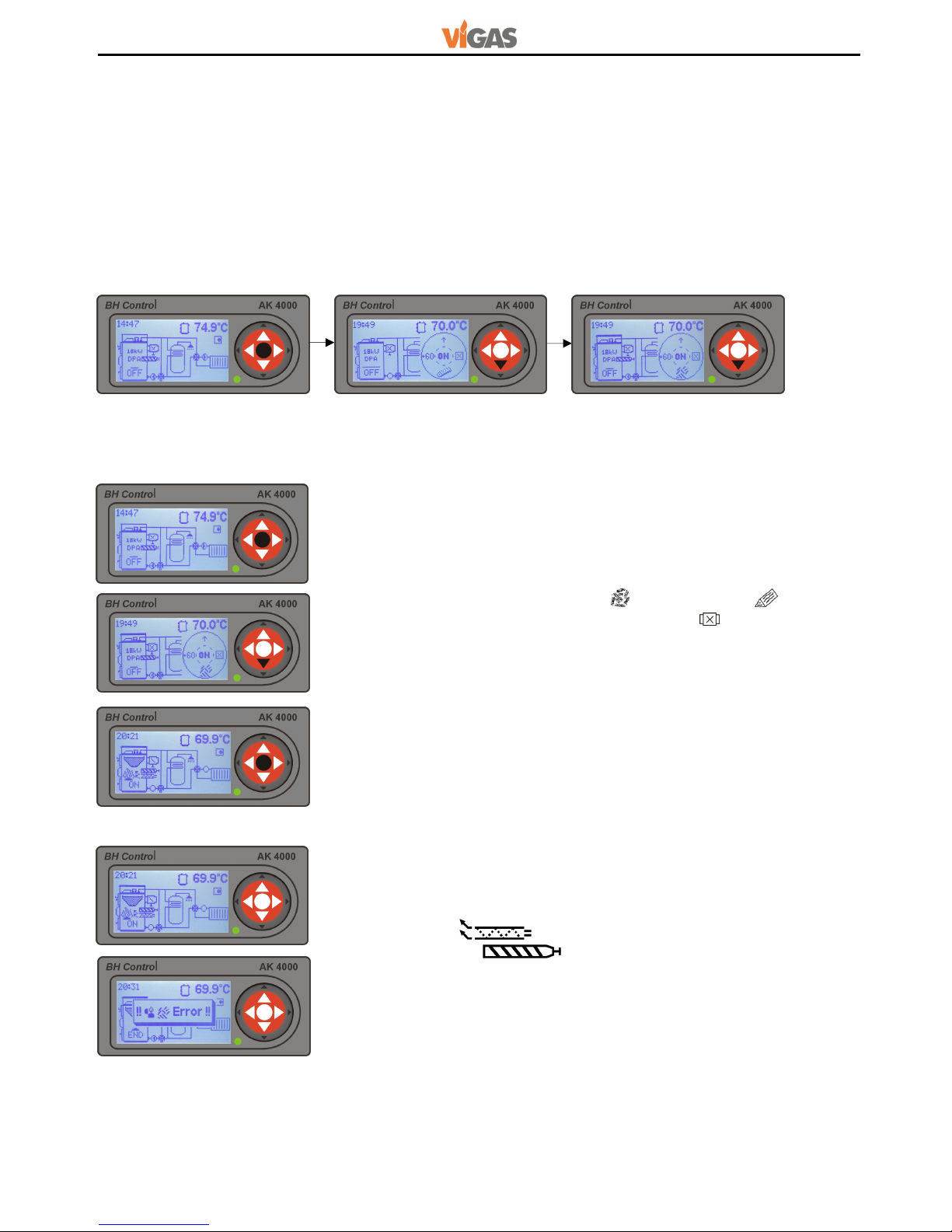
4.1 VIGAS boiler control using fuel - PELLETS
4.1.1 Switch on the boiler
4.1.2 Boiler switched on – pellet ignition mode
Symbol „OFF“ will appear, as shown on the picture, if boiler is switched
off, by pressing middle button „ENTER“, round button pictogram
appears.
Ignition mode shows symbol „ON“.
It is automatic process supported by
chimney temperature monitoring.
Discription of ignition:
1. Pump on, monitoring of current chimney gas temperature.
2. Ignition coil on ,fan will blow onto grate.
3. Screw feeder on .
4. Finishing ignition mode and switch to burning mode will start,
when
current gas temperature exceeds sensored gas temperature over 2 °C
.
The boiler will switch off, if this condition is not realized, indicated by
symbol „END“ and pellets ignition error.
Ingniton pellets error:
- Clean the burner (pic.3/24) too much ash on the burner,
- Check pellet volume in the container,
- Check igniton coil function (pic.3/35).
Fuel „PELLETS
“ Fuel
„WOOD
“
Using button select fuel pellets „ “ or fuel wood „ “.
In case,
discharge fan is used, see (chap.10.1.3) shown as this button +60
will
switch on discharge fan for 60 seconds.
It is used, for example during
boiler clean up, it will minimize dust infiltration in the boiler room area.
By pressing middle button „ENTER“
boiler gets into automatic pellet
ignition.
10
Gasifying boilers VIGAS
VIGAS 18 DPA, VIGAS 26 DPA
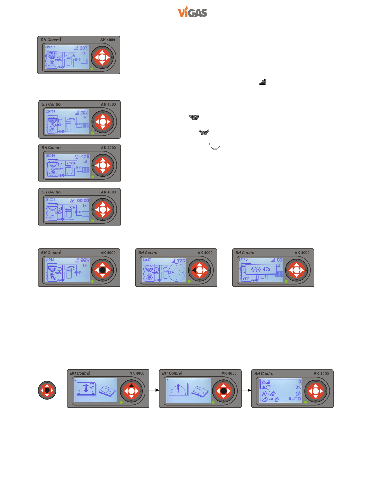
4.1.3 Boiler switched on – burning mode
4.1.4 Boiler shutdown (automatic)
4.1.5 Boiler shutdown (manually)
4.2 Parametres setting for fuel - PELLETS
Mode of combustion, the boiler will get after successful ignition of the
pellets. Status is displayed by changing the "ON" → "520C". The burning
mode, the boiler is controlled by a "PID controller based on the
temperature of the boiler and flue temperatures. If the boiler temperature
exceeds the desired temperature by 1°C, output is 0% if the temperature
drops below 3°C desired temperature, the boiler is re-ignited. Current
output is displayed in percentage as a symbol. "20%".
Inside boiler container is p
laced ultrasound sensor, which detects pellet
level. If pellets are above sensor level (container is full), this condition is
displayed by symbol „ “.
If pellets are below sensor level (container is half-
empty), this condition is
displayed by symbol „ “.
Simultaneously, information line shows
remaining time period for boiler to shutdown. This condition is displayed
by empty container symbol “ “ and sign „END“.
Pressing „ENTER“ display offers round button. Pressing button ⊳ boiler will shut down. After
shutdown, the
blowing fan is switched on. During 60s period pellet burner is being cooled down. By pressing
round
button will disappear.
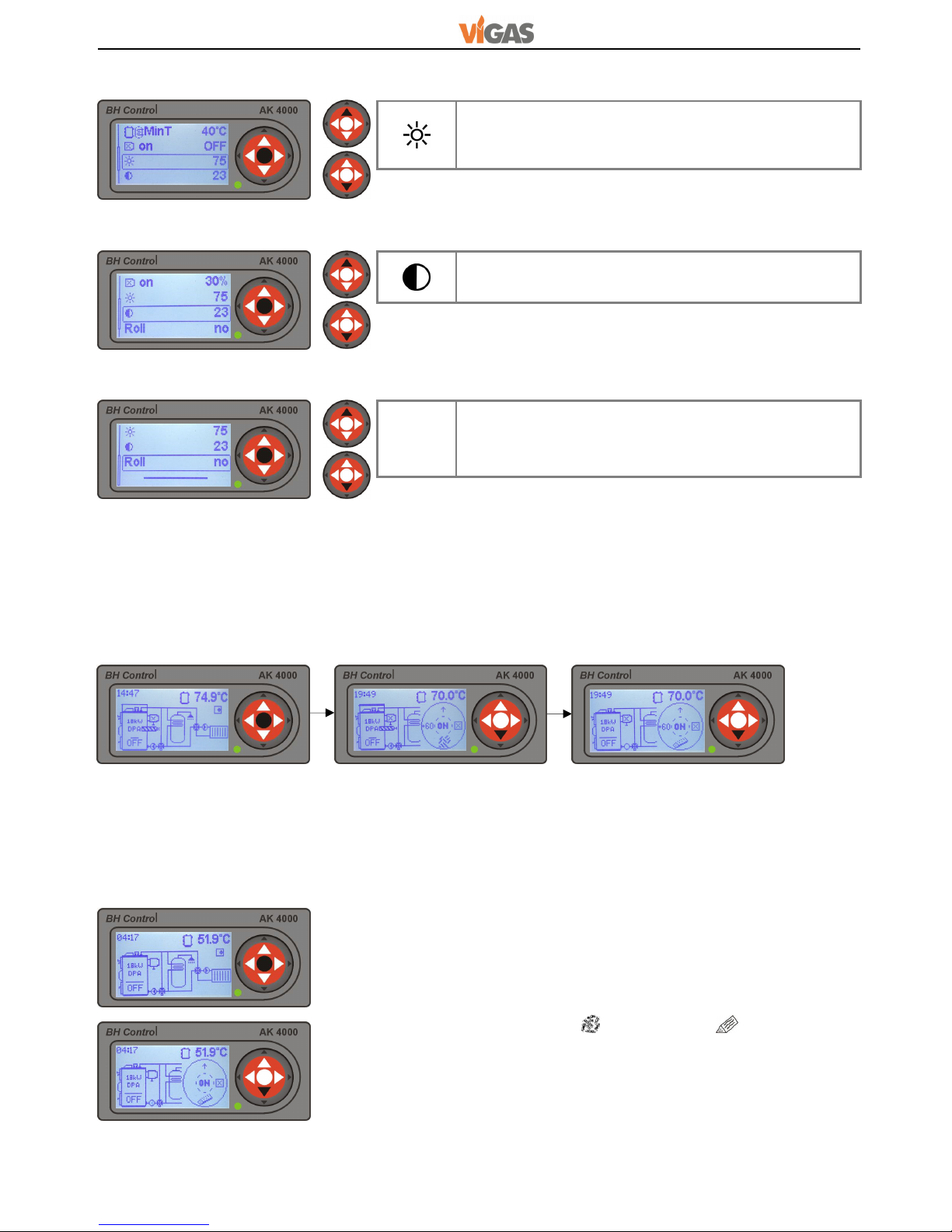
To change setting press
„ENTER“
for 2 seconds, in any boiler mode, by pressing button ▲. Parametres
setting depends on type of the boiler and its configuration.
By pressing buttons ▲ choose parameter to be changed and pressing
„ENTER“
figure starts flashing.
Using ▲ buttons select required figure and repeatedly press „ENTER“.
2sec.

11
VIGAS 18 DPA, VIGAS 26 DPA
Gasifying boilers VIGAS
Fan adjustment is possible in case you need
to increase or decrease amount of air. This figure is
possible to adjust from -5% to +15%. Figure
adjustment to „0“ meets pellet quality EN Plus A1.
Using fan adjustment:
Low chimney draft........+
High chimney draft...... -
Lower quality pellets.....+
MinT
Setting the minimum temperature in the ACCU tank.
The display is active only if the selected hydraulic
diagram of the ACCU tank (see 10.4). Setting range
25-70°C. If the boiler exceeds the desired temperature
by 1°C. there is a transition to the state of the boiler
setback . The re-start of boiler is heating up and
when the temperature drops in ACCU tank set value
for example. 40°C (for fuel "wood" and fuel "pellets").
4.2.1 Boiler power adjustment
4.2.2 Fan adjustment
4.2.3 Fuel Type setting: PELLETS - WOOD
4.2.4 Adjustment of automatic fuel transfer from "wood" to fuel "pellets"
4.2.5 Minimum temperature in the accumulation tank set-up
4.2.6 Adjustment of discharge fan speed
on
In case of installation and selection of discharge fan
(see chap.10.1.3), there is possibility using it to
increase chimney effectivity by permanent running.
Possibility to adjust speed from 30% up to 100% or
completely shutdown to „OFF“.
Correction of output can be used to increase or
decrease the time of dosing pellets in the same
period. The value can be set in the range of -3 to +3.
One step correction = change of time of dosing in one
period of 0.5 seconds. Correction can be used to
achieve optimum combustion of pellets, or
modification of the boiler output. When the quality of
the pellets is according to EN Plus A1, it is
recommended to set the correction to "0". This setting
will take effect for displaying the maximum output of
the boiler.
When you select "AUTO" will occur after burning out
of fuel "wood" and flue gas temperature reaches
end (see Sec. 5.3.2) to automatically transition to
fuel "pellets" and the subsequent continuation of
burning. In "Auto" mode is recommended temperature
shut- end 50°C. When connecting the ACCU tank,
the minimum temperature shutdown automatically
moves to the required temperature of the boiler.
If elected, "OFF" will occur after the end temperature
for the boiler and the statement "END".
/
Boiler VIGAS 18DP is a semi-automatic boiler for
burning pellets and lump wood. When using fuel
"pellets" should be selected graphic symbol .
For fast access to fuel type can be used the
round dial on boiler. See chapter 4.
12
Gasifying boilers VIGAS
VIGAS 18 DPA, VIGAS 26 DPA
4.2.7 Display brightness adjustment
4.2.8 Display contrast adjustment
4.2.9 Adjustment of scrolling information line
5. BOILER VIGAS 18 DPA fuel WOOD
Quick choice selection of fuel type using round button
5.1 Boiler control VIGAS
without discharge fan
5.1.1 Boiler switch on
Select figure for display brightness. This figure is
possible to adjust from 0 to 100.
Select contrast figure of the display. This figure is
possible to adjust from 16 to 24.
Roll
By pressing „
yes
“ information line offers current boiler
figures shown on display (pic.7), e.g. boiler power,
boiler temperature, gas temperature, etc. By pressing
„no“ choose figures for information line ▲.
When boiler is in the „OFF“ mode, by pressing middle button
„ENTER“
round button symbol will appear.
Discharge fan is an additional device for VIGAS boiler.
It prevents smoke leakage into the area
of boiler room, while filling up the boiler with fuel. See chap.13.3.
Fuel „PELLET
“ Fuel
„WOOD
“
By pressing select fuel pellet „ “ or fuel wood „ “.
When burning
wood, please select option „WOOD“
Caution:
Before pressing „ENTER“ it is necessary to start fire inside boiler
,
following chap.11.4.
 Loading...