

Page 1
INSTALLATION MANUAL
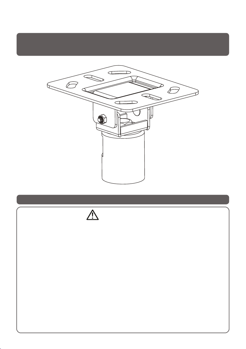
Raked Ceiling Mount Accessory
ISSUED: MAR. 2013
NOTE: Rea d the entire instr uction manual be fore you st art ins tallati on and assembly.
WARNING
• Do not begin the installation until you have read and understood all the instructions
and warnings contained in this installation sheet. If you have any questions
regarding any of the instructions or warnings, please contact your local distributor.
• This mounting bracket was designed to be installed and utilised ONLY as
specified in this manual. Improper installation of this product may cause damage
or serious injury.
• This product should only be installed by someone with good mechanical ability
who has basic building experience and fully understands this manual.
• This product is intended for indoor use only. Using this product outdoors could
lead to product failure and personal injury.
Page 2
Component Checklist
IMPORTANT: E nsu re that you h ave r ece ive d all parts a cco rdi ng to t he co mponent c hec kli st pr ior to inst all ati on.
If an y par ts ar e mis sing or fau lty, t ele phone you r loc al di str ibutor fo r a rep lac eme nt.
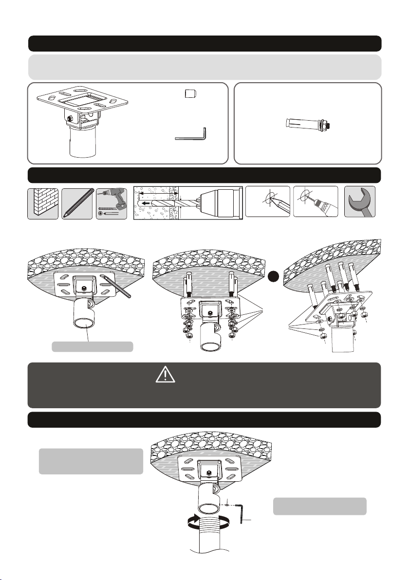
Package W
set scr ew( x1)
B
ceili ng pl ate ( x1)
A
Allen key (x1)
C
M8 (x6 )x70 i ron exp ansio n bolt
W-A
1.For Solid Brick and Concrete Mounting (fit flat roof or pitched roof)
60mm
45mm
60mm
(2.4")
(1.8")
2.4"( )
ø 12mm
(ø 1/2")
1
Mark the e xac t
loc ati on of
mounti ng ho les
2
Drill six pilot
holes
Screw ceiling
plate on the
ceiling
or
W-A
W-A
1-1/2 " int ern al di ameter
WARNING
Installers must verify that the supporting surface will safely support the combined weight of the
equipment and all attached hardware and components.
2.Installing the Pole
Threa d and t igh ten t he pole
(not in clu ded ) ont o the ceiling
plate .
B
Inser t and t igh ten o ne set
screw t o sec ure i t.
C
Page 3
INSTALLATION MANUAL
Extension Column Connector
ISSUED: MAR. 2013
NOTE: Rea d the entire instr uction manual be fore you st art ins tallati on and assembly.
WARNING
• Do not begin the installation until you have read and understood all the instructions
and warnings contained in this installation sheet. If you have any questions
regarding any of the instructions or warnings, please contact your local distributor.
• Improper installation of this product may cause damage or serious injury.
Page 4

Component Checklist
IMPORTANT: E nsu re that you h ave r ece ive d all parts a cco rdi ng to t he co mponent c hec kli st pr ior to inst all ati on.
If an y par ts ar e mis sing or fau lty, t ele phone you r loc al di str ibutor fo r a rep lac eme nt.
pole (x1)
A
Installing the Pole
1-1/2 " int ern al di ameter
tighten
tighten
Page 5

INSTALLATION MANUAL
Flat Panel Ceiling Mount Accessory
200x2 00/ 300 x30 0
400x2 00/ 400 x40 0
600x4 00/ 800 x40 0
ISSUED: MAR. 2013
7
Page 6

NOTE: Rea d the entire instr uction manual be fore you st art ins tallati on and assembly.
WARNING
• Do not begin the installation until you have read and understood all the instructions
and warnings contained in this installation sheet. If you have any questions
regarding any of the instructions or warnings, please contact your local distributor.
Component Checklist
IMPORTANT: E nsu re that you h ave r ece ive d all parts a cco rdi ng to t he co mponent c hec kli st pr ior to inst all ati on.
If an y par ts ar e mis sing or fau lty, t ele phone you r loc al di str ibutor fo r a rep lac eme nt.
• This mounting bracket was designed to be installed and utilised ONLY as
specified in this manual. Improper installation of this product may cause damage
or serious injury.
• Always use an assistant or mechanical lifting equipment to safely lift and position
the equipment.
• Tighten screws firmly, but do not over tighten. Over tightening can cause damage
to the items, This greatly reduces their holding power.
• This product is intended for indoor use only. Using this product outdoors could
lead to product failure and personal injury.
Package M
M5x14 ( x4)
unive rsa l pla te (x 1)
antis kid b loc k (x2 )
M-A
A
C
M6x14 ( x4)
M-B
set scr ew( x1)
D
M8x20 ( x4)
adapt er br ack et (x 2)
M-C
B
Allen key (x1)
E
M6x30 ( x4)
M-D
M8x30 ( x4)
M-E
washe r
M-F
(x4)
small s pac er (x 8)
M-G
big spa cer ( x4)
M-H
21
Page 7

1. Installing the Adapter Brackets
1-2 For Recessed Back Screens or to Access A/V Inputs
1-1 For Flat Back Screens
TV
TV
TV
TV
Top of the Di spl ay
M-C
M-G
M-F
M-C
M-D
M-E
M-G
M-G
M-F
M-D
M-E
M-H
M-F
M-D
M-E
M-G
M-H
M-F
Not e: Cho ose the appropr iate screws, washer s and sp acer s (if ne cessary ) acco rding to the t ype of s cree n.
· Posit ion t he ad apt er brackets as cl ose a s pos sib le to the center of t he di spl ay.
· Screw t he ad apt er br ackets onto the d isp lay.
Tig hten all screws b ut do n ot ov er ti ghten.
TV
TV
2. Attaching the Universal Plate to the Pipe
M-F
M-A
M-B
M-C
Threa d and t igh ten t he universal pl ate
onto th e pip e(n ot in cluded).
1-1/2 " int ern al di ameter
D
E
Inser t and t igh ten o ne set screw to
secur e it.
43
Page 8

3. Hooking the Display onto the Wall Mount
4. Adjustment
+5°
Tig hte n the b ottom bolts to se cur e the a dap ter brackets to t he un ive rsa l plate.
C
Insta ll bo th an tis kid blocks as clo se to t he ad apt er brackets as po ssi ble .
C
-12°
+5° -5°
Adjus t the d isp lay t o the desired ang le.
Maint ena nce
• Check t hat t he br ack et is secure and sa fe to u se at r egu lar intervals (at l eas t eve ry three months ).
• Pleas e con tac t you r distributor i f you h ave a ny qu estions.
Tig hte n all s crews on the anti ski d blo cks u sing a proper scr ewd riv er to p revent the disp lay f rom m ovi ng.
5
6
 Loading...