

Page 1
VZ-CM
Telescopic Ceiling Mount with length, rotation and tilt adjust
VZ-CM series INSTALLATION INSTRUCTIONS
VZ-CM06B
VZ-CM06W
VZ-CM18B
VZ-CM18W
Page 2
Contents
CM series
Weight Limit 2
Warning Statements 2
Ceiling Mount info 3
Assembly Component List 3
Features 5
Warranty 8
.........................................................................................................................................................................................................
............................................................................................................................................................................................
...................................................................................................................................................................................................
....................................................................................................................................................................................
.................................................................................................................................................................................................................
............................................................................................................................................................................................
.............................................................................................................................................................................
..................................................................................................................................................................................................
........................................................................................................................................................................................................
....................................................................................................................................................................................
...............................................................................................................................................................................................................
Weight Limit
THE CEILING STRUCTURE MUST BE CAPABLE OF
Maximum Monitor Weight:
36.82 lbs
SUPPORTING AT LEAST FIVE TIMES THE
WEIGHT OF THE MONITOR. IF NOT, THE
CEILING STRUCTURE MUST BE REINFORCED.
6Installing the Mount
6Installing a Monitor to the Pole
7Leveling the Pole
7Adjusng the Height
7Installing the Safety Cable
Warning Statements
PRIOR TO THE INSTALLATION OF THIS PRODUCT, THE INSTALLATION INSTRUCTIONS MUST BE READ AND COMPLETELY UNDERSTOOD. KEEP THESE
INSTALLATION INSTRUCTIONS IN AN EASILY ACCESSIBLE LOCATION FOR FUTURE REFERENCE.
PROPER INSTALLATION PROCEDURE BY A QUALIFIED SERVICE TECHNICIAN MUST BE FOLLOWED, AS OUTLINED IN THESE INSTALLATION
INSTRUCTIONS. FAILURE TO DO SO COULD RESULT IN PROPERTY DAMAGE, SERIOUS PERSONAL INJURY, OR EVEN DEATH.
SAFETY MEASURES MUST BE PRACTICED AT ALL TIMES DURING THE ASSEMBLY OF THIS PRODUCT. USE PROPER SAFETY EQUIPMENT AND TOOLS
FOR THE ASSEMBLY PROCEDURE TO PREVENT PERSONAL INJURY.
ViewZ USA DOES NOT WARRANT AGAINST DAMAGE CAUSED BY THE USE OF ANY ViewZ USA PRODUCT FOR PURPOSES OTHER THAN THOSE
FOR WHICH IT WAS DESIGNED OR DAMAGE CAUSED BY UNAUTHORIZED ATTACHMENTS OR MODIFICATIONS, AND IS NOT RESPONSIBLE FOR
ANY DAMAGES, CLAIMS, DEMANDS, SUITS, ACTIONS OR CAUSES OF ACTION OF WHATEVER KIND RESULTING FROM, ARISING OUT OF OR IN ANY
MANNER RELATING TO ANY SUCH USE, ATTACHMENTS OR MODIFICATIONS.
CHANGES OR MODIFICATIONS NOT EXPRESSLY APPROVED BY THE PARTY RESPONSIBLE FOR COMPLIANCE COULD VOID THE USERS AUTHORITY TO
OPERATE THE EQUIPMENT.
At least two qualied people should perform the assembly procedure. Personal injury and/or property damage can result from dropping or
mishandling the at-panel.
If mounng to wall studs or ceiling studs, make sure that the mounng screws are anchored into the center of the wall studs or ceiling studs. Use
of an edge-to-edge stud nder is recommended.
Using replacement parts or accessories other than from the manufacturer may void the warranty.
Be aware of the mounng environment. If drilling and/or cung into the mounng surface, always make sure that there are no electrical wires in
wall. Cung or drilling into an electrical line may cause serious personal injury.
Make sure there are no water or natural gas lines inside the wall where the mount is to be located. Cung or drilling into a water or gas line may
cause severe property damage or personal injury.
This product is intended for indoor use only. Use of this product outdoors could lead to product failure and/or serious personal injury.
Do not install near sources of high heat. Do not install on a structure that is prone to vibraon, movement or chance of impact.
Contact ViewZ with any quesons:
(888) 998-4399
techsupport@viewzusa.com
2 Installation InstructionsVisit the ViewZ USA website at http://www.viewzusa.com
Page 3
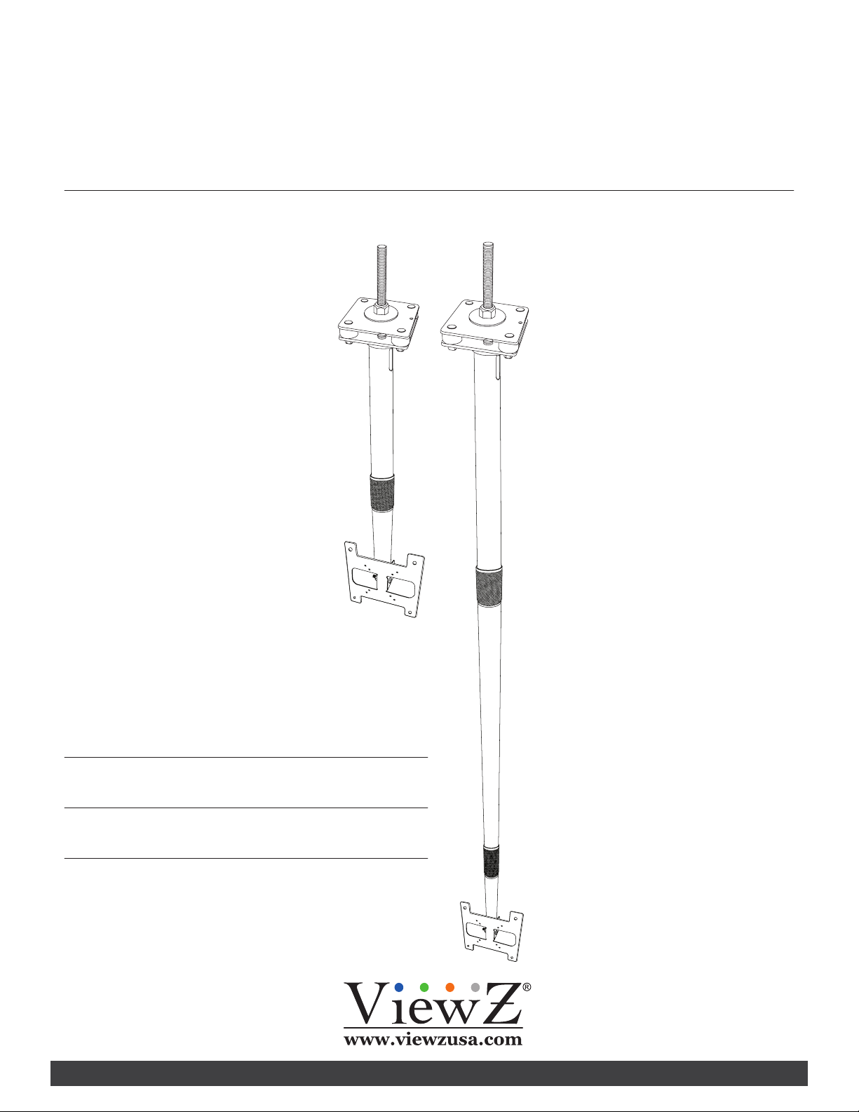
CM series
Telescopic Monitor ceiling mount Info
This bracket is designed to mount a monitor from the ceiling structure. It can be used with the exisng truss structure of the building
or in conjuncon with a channel strut. There are four lengths of brackets available.
• Part #
• Part #
• Part #
• Part #
CM06B
CM06W
CM18B
CM18W
Length of 3' to 6'
Length of 3' to 6'
Length of 6' to 18'
Length of 6' to 18'
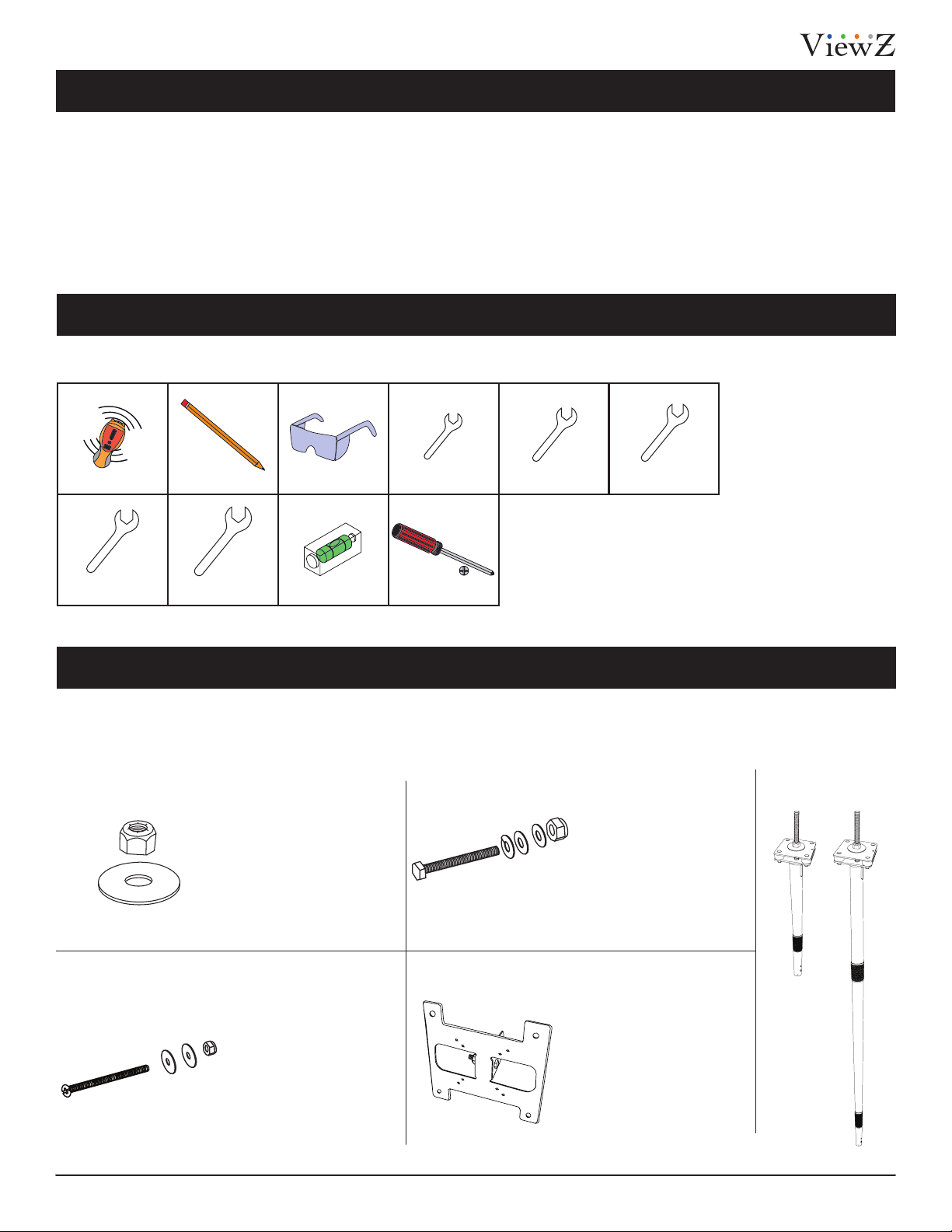
Installation Tools
The following tools may be required depending on your installaon.
Electronic Stud Finder
3/4" wrench
Pencil
5/16" wrench
Protecve Eye-wear
Level
7/16" wrench
Phillips Screwdriver
7 mm wrench 10 mm wrench
Assembly Components
Your ViewZ mount product is shipped with all proper installaon hardware and components. If there are parts missing
and/or damaged, please stop the installaon and contact ViewZ USA at (888)-998-4399.
q 1/2”-13 x L15
Lock-Nut (1 pc.)
q
w
q
w φ 50 x φ 13.5 x T3.1
Washer(1 pc.)
w
q M4 x 0.7 x L 45 screw (1 pc.)
w M4 x 0.7 x L 4.9
Lock-Nut(1 pc.)
e φ 12 x φ 4.3 x T0.8
e
Washer(2 pcs.)
e
w
q
q 1/4W20 x L50.7
Screw (1 pc.)
w φ 12 x φ 6.6 x T1
Washer(2 pcs.)
r
e φ 12.2 x φ 6.6 x T2
Washer(1 pc.)
r 1/4W20 x L7.7
Lock-Nut(1 pc.)
q Bracket (1 pc.)
Pole Mount Assembly
6 (1pc.) / 18 (1pc.)
3Installation Instructions Visit the ViewZ USA website at http://www.viewzusa.com
Page 4

Assembly Components (cont’d)
CM06B & CM06W CM18B & CM18W
M4 x 0.7 x L10 mm Screw (Qty 1)
M6 x 1.0x L12 mm Screw (Qty 1)
φ 10 x φ 4.3 x T1 Washers (Qty 2)
CM series
φ 2.5 x φ 1.5 x L4752 mm
U-bolt cable
(Qty 1)
1/8" U-bolt cable clamp (Qty 1)
M4 x 0.7 x L6 mm Screws (Qty 4)
φ 10 x φ 4.3 x T1 Washers (Qty 4)
M6 x 1.0 x L12 mm Screws (Qty 4)
φ 12 x φ 6.6 x T1 Washers (Qty 4)
φ 2.4 x φ 1.6 x L7620 mm
U-bolt cable
(Qty 1)
4 Installation InstructionsVisit the ViewZ USA website at http://www.viewzusa.com
Page 5

CM series
Features
1/2”-13 Lock Nut
Fender Washer
Truss or Channel Strut
1/4”-20 x 2”
M4 x 45 mm
M4 Washer
M4 Washer
M4 Lock-Nut
1/4” Washer
1/4”-20 Lock Nut
1/4” Lock Washer
1/4” Washer
M6 x L12 mm VESA screws ( 4 places )
5Installation Instructions Visit the ViewZ USA website at http://www.viewzusa.com
Page 6

Installation
CM series
Securing Mount to Building
1) Insert threaded rod between truss gap or into hole in channel strut.
2) Place 1/2” fender washer over the threaded rod and then 1/2” lock
nut.
3) Tighten the 1/2”-13 lock nut using a 3/4” wrench.
Mounting Monitor to Pole
1) 1. If your monitor is supplied with a VESA plate already mounted
on the back, simply ensure the four M4 screws are in place and
tightened. If the mount is not already attached, connect it using the
supplied M4 x 8mm VESA screws (4-places).
*NOTE: Some installations may require running power and video
cables prior to attaching the monitor bracket to the pole. If this is
the case, do so before continuing to step 2.
2) Hold the monitor with attached bracket up to the end of the pole
mount, and line up the wings of the bracket to the holes in the end
of the pole. Insert the 1/4”-20 x 2” bolt, lock washer, washers, and
lock nut in place according to the illustration on the right. You will use
7/16” and 10mm wrenches to fully tighten in step 4.
3) Install the M4 x 45mm screw, washers, and lock nut into the upper
slotted hole according to the illustration on the right. You will use a
#2 Phillips screwdriver and a 7mm wrench to fully tighten in the next
step.
4) Tighten the fasteners to secure the monitor at the desired angle.
*NOTE: Avoid over-tightening which can cause the pole to indent.
M4 x 45 mm
1/4”-20 x 2”
1/4” Lock Washer
1/4” Washer
1/2”-13 Lock Nut
Fender Washer
Truss or Channel Strut
M4 Washer
M4 Washer
M6 x L12 mm VESA screws ( 4 places )
M4 Lock-Nut
1/4” Washer
1/4”-20 Lock Nut
This stand is intended for use only with the maximum
weights indicated. Use with products heavier than the
maximum weights indicated may result in instability
Max Load:
16.7 kg / 36.82 lbs
causing possible injury. This product is intended to mount
to a steel support truss, or channel strut.
Leveling the Pole
1) You can ensure the pole is plumb by tightening the 1/4”-20 lock nuts
on the top of the pole where it attaches to the structure using a 7/16”
wrench.
2) Place a level on the pole and tighten the nuts that correspond to the
61
/
7
direction that the pole needs to move (see illustration on the right).
3) Check and adjust 2 adjacent sides of the pole until it is plumb in each
direction.
Washer Pole will move
in the direcon of the
ghtened bolt
6 Installation InstructionsVisit the ViewZ USA website at http://www.viewzusa.com
1
0
Page 7

CM series
Installation
Adjusting Height
1) Hold the lower pole (where it connects to the monitor) while loosening the center collar by turning it counter-clockwise (see illustration on left
below). Extend the pole by gently lowering it to the desired length.
2) Once the proper length has been maintained, lock the pole in position by rotating the center collar clockwise. The collar should be hand
tightened as snug as possible to prevent the pole from expanding. (see illustration on right below)
Loosen
Hold lower pole secon and turn
counter-clockwise to loosen
Tighten
Secure assembly by turning collar clockwise:
hand ghten as snug as possible
Installing the Safety Cable
1) Run the safety cable into the cable management hole in the top of the pole, and out through the bottom of the pole. The crimped eyelet end
will connect to the monitor.
2) VESA 100 x 100 - Remove one of the M4 x 6mm VESA mount screws from the monitor-bracket assembly, then connect the crimped eyelet end
of the safety cable to the mount using the supplied M4 x 10mm screw. You can discard the unused M4 x 6mm VESA mount screw that has been
removed as it is no longer needed.
3) VESA 200 x 200 - Use one of the M6 x 12 mm VESA mount screw to connect the crimped eyelet end of the safety cable to the mount.
4) Connect the top end of the safety cable by inserting it through a hole in the truss or channel strut, and fasten using the U-Bolt cable clamp. Pull
any remaining slack from the safety cable, and fully tighten the U-Bolt using a 5/16” wrench. Cut or loop any excess cable.
VESA 100 x 100 - Remove original M4 x L6mm VESA screw &
replace with M4 x L10mm screw
VESA 200 x 200 - Use M6 x L12mm VESA screw
U-Bolt Cable Clamp
Cord Management Hole
7Installation Instructions Visit the ViewZ USA website at http://www.viewzusa.com
Page 8

CM series
Warranty
ViewZ USA
LIMITED LIFETIME WARRANTY
What and Who is Covered by this Limited Warranty and for How Long
ViewZ USA warrants this product to be free from defects in material and workmanship for the lifeme of the original owner of this
product. The limited warranty is valid only for the original purchaser of the product.
What ViewZ USA Will Do
At the sole opon of ViewZ USA, ViewZ USA will repair or replace any product or product part that is defecve. If ViewZ USA chooses
to replace a defecve product or part, a replacement product or part will be shipped to you at no charge, but you must pay any labor
costs.
What is Not Covered; Limitaons
ViewZ USA DISCLAIMS ANY LIABILITY FOR DAMAGE TO MOUNTS, ADAPTERS, DISPLAYS, PROJECTORS, OTHER PROPERTY, OR
PERSONAL INJURY RESULTING, IN WHOLE OR IN PART, FROM IMPROPER INSTALLATION, MODIFICATION, USE OR MISUSE OF ITS
PRODUCTS.
ViewZ USA DISCLAIMS ALL OTHER WARRANTIES, EXPRESS OR IMPLIED, INCLUDING WARRANTIES OF MERCHANTABILITY AND FITNESS
FOR A PARTICULAR PURPOSE. ViewZ USA IS NOT RESPONSIBLE FOR INCIDENTAL OR CONSEQUENTIAL DAMAGES, INCLUDING BUT
NOT LIMITED TO, INABILITY TO USE ITS PRODUCTS OR LABOR COSTS FOR REMOVING AND REPLACING DEFECTIVE PRODUCTS OR
PARTS. SOME STATES DO NOT ALLOW THE EXCLUSION OR LIMITATION OF INCIDENTAL OR CONSEQUENTIAL DAMAGES, SO THE
ABOVE LIMITATION OR EXCLUSION MAY NOT APPLY TO YOU.
What Customers Must Do for Limited Warranty Service
If you discover a problem that you think may be covered by the warranty you MUST REPORT it in wring to the address below within
thirty (30) days. Proof of purchase (an original sales receipt) from the original consumer purchaser must accompany all warranty
claims. Warranty claims must also include a descripon of the problem, the purchaser’s name, address, and telephone number.
General inquiries can be addressed to ViewZ USA Customer Service at 1-888-998-4399. Warranty claims will not be accepted over the
phone or by fax.
ViewZ USA
An: Warranty Claim
177 W. Orangethorpe Ave.
Placena, CA 92870
How State Law Applies
THIS WARRANTY GIVES YOU SPECIFIC LEGAL RIGHTS, AND YOU MAY ALSO HAVE OTHER RIGHTS WHICH VARY FROM STATE TO STATE.
Disclaimer
ViewZ USA intends to make this manual accurate and complete. However, ViewZ USA makes no claim that the informaon contained
herein covers all details, condions or variaons, nor does it provide for every possible conngency in connecon with the
installaon or use of this product. The informaon contained in this document is subject to change without noce or obligaon of
any kind. ViewZ USA makes no representaon of warranty, expressed or implied, regarding the informaon contained herein. ViewZ
USA assumes no responsibility for accuracy, completeness or suciency of the informaon contained in this document.
Contact Us
NORTH AMERICA
177 W. Orangethorpe Ave.
Placena, CA 92870
USA and Canada
Phone: 1-888-998-4399
Fax: 1-714-996-1138
Other Locaons
Phone: (001) 888-998-4399
© ViewZ USA
Fax: (001) 714-996-1138
8 Installation InstructionsVisit the ViewZ USA website at http://www.viewzusa.com
 Loading...