

Page 1

SXT1811
18.1” SXGA TFT NEMA 4/12
Flat Panel Monitor
User’s Guide
301810(B) (was document no. 920A0008 version 1.0), revised 08/00 Viewtronix
Page 2
Viewtronix reserves the right to make changes in specifications described herein at any time without
notice in order to improve design and reliability. Viewtronix does not assume any responsibility for the
use of any circuitry described; no circuit patent licenses are implied. Viewtronix assumes no responsibility
for damage caused by misuse or improper use of its products.
WARRANTY
Viewtronix warrants to Customer that the Products will be free from defects in material and
workmanship under normal use and service for a period of one year from date of invoice. Customer’s
exclusive remedy for breach of this warranty is that Viewtronix will either (i) repair or replace, at its option,
any Product which fails during the warranty period because of such defect (if Customer promptly reported
the failure to Viewtronix in writing) or, (ii) if Viewtronix is unable to repair or replace, Viewtronix will refund
the purchase price of the Product upon its return to Viewtronix. This warranty does not apply to any
Product which has been subjected to misuse, abnormal service or handling, or which has been altered or
modified in design or construction, or which has been serviced by anyone other than Viewtronix. The
warranty set forth herein is in lieu of, and exclusive of, all other warranties, express or implied.
Document No. 301810(B) (was 920A0008 version 1.0),
Released 08/00
2
Page 3

Table of Contents
WARRANTY ..................................................................................................................................................2
Table of Contents ..........................................................................................................................................3
Introduction ....................................................................................................................................................4
Video Modes Supported ................................................................................................................................4
Specifications ................................................................................................................................................5
Front and Side View of Monitor .....................................................................................................................6
Installation of Monitor ....................................................................................................................................6
Cutout Pattern for Monitor .............................................................................................................................7
Front Panel Controls......................................................................................................................................7
Mode and Image Adjustment ........................................................................................................................8
Summary of On Screen Display (OSD) Functions ........................................................................................9
VGA Input Connector Pin Out .....................................................................................................................12
3
Page 4
Introduction
The SXT1811 is an 18.1” SXGA (1280 x 1024) TFT industrial flat panel monitor for use in NEMA
4 and NEMA 12 applications. Graphics and text can be displayed on the monitor in up to 16.7 million
colors and in the modes listed below. Additionally, PAL NTSC and SECAM video can be displayed either
full screen or as a picture in picture overlaid on the PC screen. When the monitor is being driven in
modes other than SXGA, it will automatically expand and scale the image to fill all 1280 x 1024 pixels.
The unit is fully self-contained needing only to be panel mounted in an appropriate enclosure and
connected to 120/240 VAC and a VGA source. The monitor features a bright 200-nit LCD display with
50,000-hour backlights and conveniently located front panel controls with on screen menus for easy set
up and adjustment. Viewing angle is 160 degrees vertical and 160 degrees horizontal. The SXT1811 is
available with an optional integrated analog resistive touch screen, 304 stainless steel bezel and 1836VDC input. Each SXT1811 is shipped complete with user manual, mounting hardware and all cables.
Monitors equipped with touch screens are shipped with drivers for Windows 95 , 98 and Windows
NT .
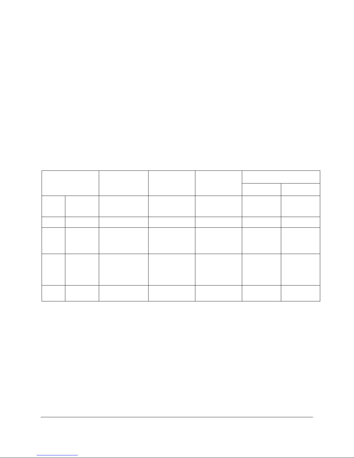
Video Modes Supported
MODE
SYNC RATE
KHZ
HORIZONTAL
VGA VESA
IBM 720 X 400 31.5
SVGA VESA
XGA VESA
SXGA VESA
640 x 480
800 x 600
1024 x 768
INTERLACED
1280 X 1024
31.5
37.9
37.5
43.3
37.9
35.1
37.9
48.1
46.9
53.7
48.4
56.5
57.5
60.0
68.7
35.5
64.0
78.1
80.0
VERTICAL SYNC
RATE
Hz
60
72
75
85
70
85
56
60
72
75
85
60
70
72
75
85
87
60
72
75
DOT
FREQUENCY
MHZ
25.175
31.500
31.500
36.000
28.322
35.500
36.000
40.000
50.000
49.500
56.250
65.000
75.000
75.000
78.780
94.500
44.900
108.000
135.000
135.000
EXPANSION FACTOR
Vertical HORIZONTAL
22
1.7 1.7
1.5 1.5
1.25 1.25
11
4
Page 5

Specifications
DISPLAY
Parameter Specification
Display Size 18.1” Diagonal
Active Area 14.134” (H) x 11.307” (V)
Pixel Format 1280 (H) x 1024 (V) Pixels (1 Pixel = R + G + B Dots)
Brightness 200 Nit Typical
Back Light Life 50,000 Hrs Typical
Contrast Ratio 300:1 Typical
Viewing Angle 160 Degrees Vertical and Horizontal
Number Colors 16.7 Million
PHYSICAL
PARAMETER SPECIFICATION
Monitor Outside Dimensions 15.70” (H) x 18.51” (W) x 3.73” (D)
Monitor Weight 28 Pounds
Operating Temperature 0 ~ 50 Degrees Centigrade
Storage Temperature -20 ~ 60 Degrees Centigrade
Relative Humidity < 95%, Ta < 40 Degrees Centigrade, < 85%,40 < Ta < 50 Degrees Centigrade
Operating Vibration 5 ~ 500 Hz, 1G
Operating Shock 15G for 11ms
Operating Altitude 10,000 Feet Above Sea Level
PARAMETER SPECIFICATION
Input Voltage 90 ~ 264 VAC, 47 ~ 440 Hz (18-36 VDC Optional)
Input Power 85 W
Parameter Specification
NEMA Rating NEMA 4/12 From front when properly installed in an enclosure. (Optional Stainless
EMC FCC Part 15, Class A / Industry Canada ICES-003 Issue 2, Rev. 1 / EN61000-4-2, 4-3,
Safety UL-1950 / CUL/CSA 22.2 950 M93/ EN60950 / Low Voltage Directive 73/23/EEC
ELECTRICAL
Compliance
Steel Bezel Available)
4-4 / EMC Directive 89/336/EEC (Pending)
5
Page 6

Front and Side View of Monitor
POWER
MENU
SEL UP
SEL DN
DEC
INC
SET
OFF ON
UP
O
18.51"
3.35"
Viewtronix
15.70"
I
Installation of Monitor
This monitor is intended to be mounted in and used where NEMA 4 and NEMA 12 type
enclosures are employed. When mounted properly, the monitor meets or exceeds the sealing
requirements set forth in the NEMA 4 and NEMA 12 specifications. The monitor uses “U”-shaped clips
and a special gasket to achieve the proper seal.
To install the monitor, make a cutout per the diagram below in one of the walls of your NEMA
enclosure. Enclosures made of heavier gauge metal work better in that they won’t deform or bend as
easily when the monitor’s sealing gasket is compressed. Next hold the monitor in place while you install
the mounting clips. Tighten the clips in a cross pattern. This will help to develop an even pressure on the
sealing gasket. Tighten the clips to the point were the back of the monitor’s front bezel just begins to
contact the front of the NEMA enclosure. DO NOT OVER TIGHTEN AS DAMAGE CAN RESULT IN THE
MONITOR CAUSING LOSS OF SEALING INTEGRITY.
6
Page 7
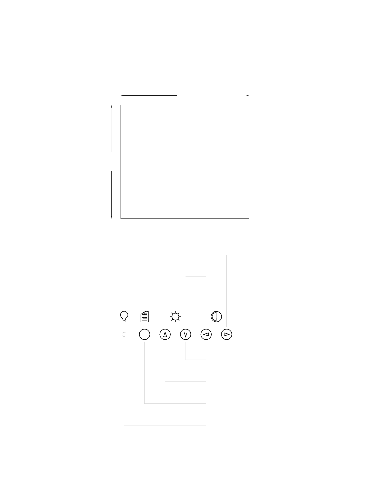
Cutout Pattern for Monitor
14.93"
+/- .02"
PANEL CUT OUT
17.74"
+/- .02"
Front Panel Controls
INCREASE - INCREASES THE VALUE
OF THE SELECTED MENU ITEM
ALSO INCREASES CONTRAST
DECREASE - DECREASES THE VALUE
OF THE SELECTED MENU ITEM
ALSO DECREASES CONTRAST
SELECT DOWN - MOVES THE SELECTED
MENU ITEM DOWN TO THE NEXT ITEM
ALSO INCREASES BRIGHTNESS
SELECT UP - MOVES THE SELECTED
MENU ITEM UP TO THE NEXT ITEM
ALSO DECREASES BRIGHTNESS
MENU - TURNS ON SCREEN
DISPLAY MENU ON OR OFF
POWER ON LED
7
Page 8

Mode and Image Adjustment
Not all video controllers produce exactly the same video output levels or the same timing. The
following procedure can be used to select the desired video mode as well as optimize your monitor’s
image quality. When adjusting your monitor, the use of video test software such as DisplayMate for
Windows by SONERA Technologies can be very beneficial.
The SXT1811 automatically adjusts to most incoming video signals. Usually, only brightness, contrast
and phase need to be adjusted by the user. “On Screen Programming” helps make setup and adjustment
of these settings easy. The menus are selected and the menu items are adjusted using the buttons
located on the monitor’s front panel. These buttons are enabled or disabled by a rocker switch labeled
“SET UP” located on the side of the monitor. This feature is provided to inhibit tampering once the
monitor is in actual use. Turn the SET UP switch to the ‘On’ position to enable set up and adjustment. If
you are using a “Plus and Play” operating system adjust your desktop display settings to the following
before connecting the SXT1811 to your computer:
Vertical Refresh: 60Hz
Resolution: 1280 x1024
If you are using a “Plug and Play” operating system, the monitor type and default settings are
automatically detected by the operating system. If you are not using “Plug and Play”, set your monitor
type to:
Manufacture: (Standard monitor type)
Model: Super VGA 1280 x 1024 @75Hz
Vertical Refresh: 60Hz
Resolution: 1280 x1024
Once the monitor is powered up, press the menu button. After the On Screen Display (OSD)
menu appears select the “Brightness and Contrast” function by continuing to depress the menu button
until it’s graphic is highlighted.
Once this graphic is highlighted the following image will appear:
Brightness Increase/decrease panel brightness level, total: 100 steps
Contrast
Increase/decrease panel contrast level, total: 100 steps
Use the ⇑ and ß buttons to select either contrast or brightness. Now use ⇐ and Þ buttons to set
the desired level. Once brightness and contrast have been set the phase should be adjusted. Continue
pressing the menu button until “Frequency and Phase” graphic is highlighted.
Once this graphic is highlighted the following image will appear:
Frequency Adjust the image horizontal size
Phase
Fine-tune the data sampling position (adjust image quality)
8
Page 9
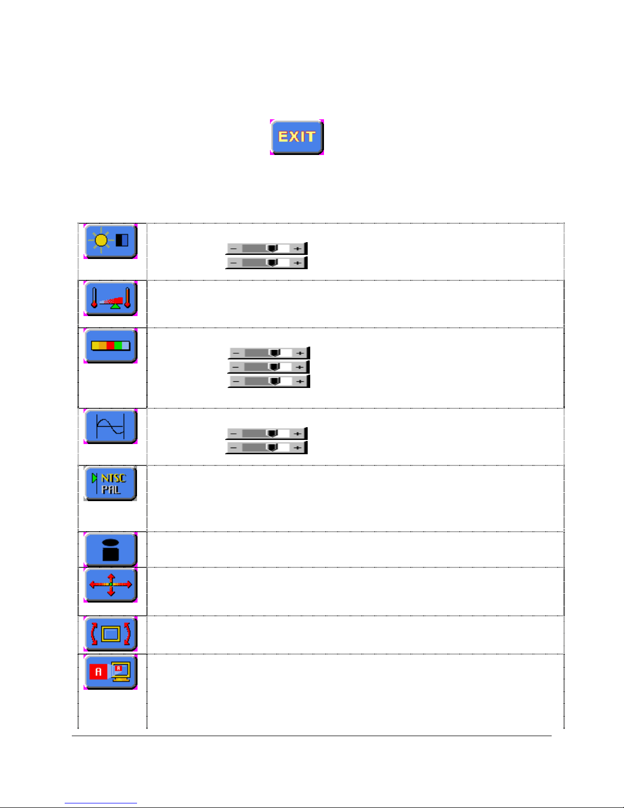
Use the ⇑ and ß buttons to select phase. Now use ⇐ and Þ buttons to fine-tune the image quality. After
completing this adjustment, exit the set up menu by either waiting about five seconds without further
button depressions or by hitting the menu button and scrolling until the Exit graphic is highlighted. Once
the following graphic is highlighted press the Þ to exit.
Summary of On Screen Display (OSD) Functions
Brightness and Contrast :
Brightness
Contrast
Color Temperature : 9500K / 8000K / 6500K / 5000K
Adjust the warmness of the image displayed. The higher temperature the coolest image looks like. The lower
temperature the warmest image looks like.
Video Adjustment : (DISPLAYED IN VIDEO MODE ONLY)
Color:
Tint:
Sharpness:
Video Type: DVD / VCR change brand width to match the source
Frequency and Phase : (DISPLAYED IN PC MODE ONLY)
Frequency
Phase
Video System : Select video system and input signals (DISPLAYED IN VIDEO MODE ONLY)
AUTO : automatic detection of NTSC and PAL system (not applicable in SECAM system)
NTSC / NTSC 4.43 : manual select NTSC system
PAL / PAL M : manual select PAL system
SECAM : manual select SECAM system
Status : (DISPLAYED IN PC MODE ONLY)
Increase/decrease panel brightness level, total: 100 steps
Increase/decrease panel contrast level, total: 100 steps
adjust video color level
adjust video tint level
adjust video image sharpness level
Adjust the image horizontal size
Fine tune the data sampling position (adjust image quality)
Display graphic information: resolution and frequency
Position :
Image up/down : Use ⇑ and to move the image vertically
Image left/right : Use ⇐ and Þ buttons to move the image horizontally
Rotation : (DISPLAYED IN VIDEO MODE ONLY)
Rotates the image from landscape format to portrait format.
Picture in Picture : (DISPLAYED IN PC MODE ONLY)
PIP Size : Off / 1 / 2 / 3 Select PIP window size: close, size 1, size 2 & size 3
PIP Source : Auto / Comp / SVid Select video source to be display in PIP window:
Auto – automatic detection of Composite or S video
Comp – manual select composite video only
SVid – manual select S-video only
9
Page 10

Horizontal Position adjust the position of the PIP window horizontally
Vertical Position
Advanced PIP Settings :
Brightness
Contrast
Sharpness
Tint
Color
Video Scaling : (DISPLAYED IN VIDEO MODE ONLY)
Use the ⇑ and arrow keys to select the following scaling modes.
Normal
Letterbox
Letterbox with Subtitles
Nonlinear Scaling Modes : Horiz Clipping / Horiz Offset / Horiz Stretch / Vert Clipping / Vert Offset /
Vert Stretch
Graphic Scaling Modes : (DISPLAYED IN PC MODE ONLY)
Use the ⇑ and arrow keys to choose a scaler mode.
Use the ⇐ and Þ arrow keys to modify a following scaler parameters.
One to One :
Horizontal Pan
Vertical Pan
adjust the position of the PIP window vertically
adjust the image brightness of the PIP window
adjust the image contrast of the PIP window
adjust the image sharpness of the PIP window
adjust the color of the image of the PIP window
adjust the tint of the image of the PIP window
Fill Screen : enable full screen expansion for lower resolution Image
Fill to Aspect ratio : enable fill screen expansion for lower resolution image according to aspect ratio.
Nonlinear Scaling Modes : Horiz Clipping / Horiz Offset / Horiz Stretch / Vert Clipping / Vert Offset /
Vert Stretch
Language : Select OSD menu language display
English only
Video source : Select the input video signal
Analog RGB / Component Video / Composite Video / S-Video
Utilities :
User Setting : User Timeout : adjust the OSD menu timeout period in a step of 5 seconds
OSD Setting : OSD Horz Position :
Freeze Frame : Freeze the image (use “Þ” button)
Zoom : Zoom level : enable the zoom in function on the image displayed.
Use “Þ” button to zoom in the image.
Use “⇐ “button to decrease the zoomed image.
DPMS : Disable / Enable the DPMS function
Auto Source Select : Off / Low / High (disable or enable video source detection)
move the OSD menu horizontally
OSD Vert Position :
OSD Background : Translucent / Opaque
move the OSD menu vertically
Horizontal Pan :
Vertical Pan :
10
Page 11
Direct Access #1: Define the hot key function (⇐ and Þ) for one of the following
adjustments : Brightness / Contrast / Volume / Freeze / Zoom / Video Source*
Direct Access #2: Define the hot key function (⇑ and ) for one of the following
adjustments : Brightness / Contrast / Volume / Freeze / Zoom / Video Source*
Display Orientation : Normal / Horizontal Inverse / Vertical Inverse / Inverse
Calibrate RGB Gain : Color Calibration (DISPLAYED IN PC MODE ONLY)
Load Factory Defaults : Recall factory default settings.
* By pressing the hot key, the source is in sequence of Analog RGB/Component Video/Composite Video/SVideo.
Volume :
Adjust the audio volume level (functions only if the audio add-on installed)
Exit menu
Pressing the Þ exits the main menu
11
Page 12

VGA Input Connector Pin Out
SIGNAL NAME 15-PIN D-SHELL
(FEMALE)
Red 1
Green 2
Blue 3
4
GND-Digital 5
GND-Red return 6
GND-Green return 7
GND-Blue return 8
9
GND-Digital 10
11
12
Hsync 13
Vsync 14
15
12
Page 13

Xycom Automation, Inc.
734-429-4971 • Fax: 734-429-1010
1-800-AT-XYCOM • http://www.xycom.com
© 2001 Xycom Automation, Inc. All rights reserved. Printed in US. All brand or product names are the property of their respective owners.
Specifications may change without notice.
Northern Europe Sales: +44-1604-790-767
Southern Europe Sales: +39-011-770-53-11
 Loading...