

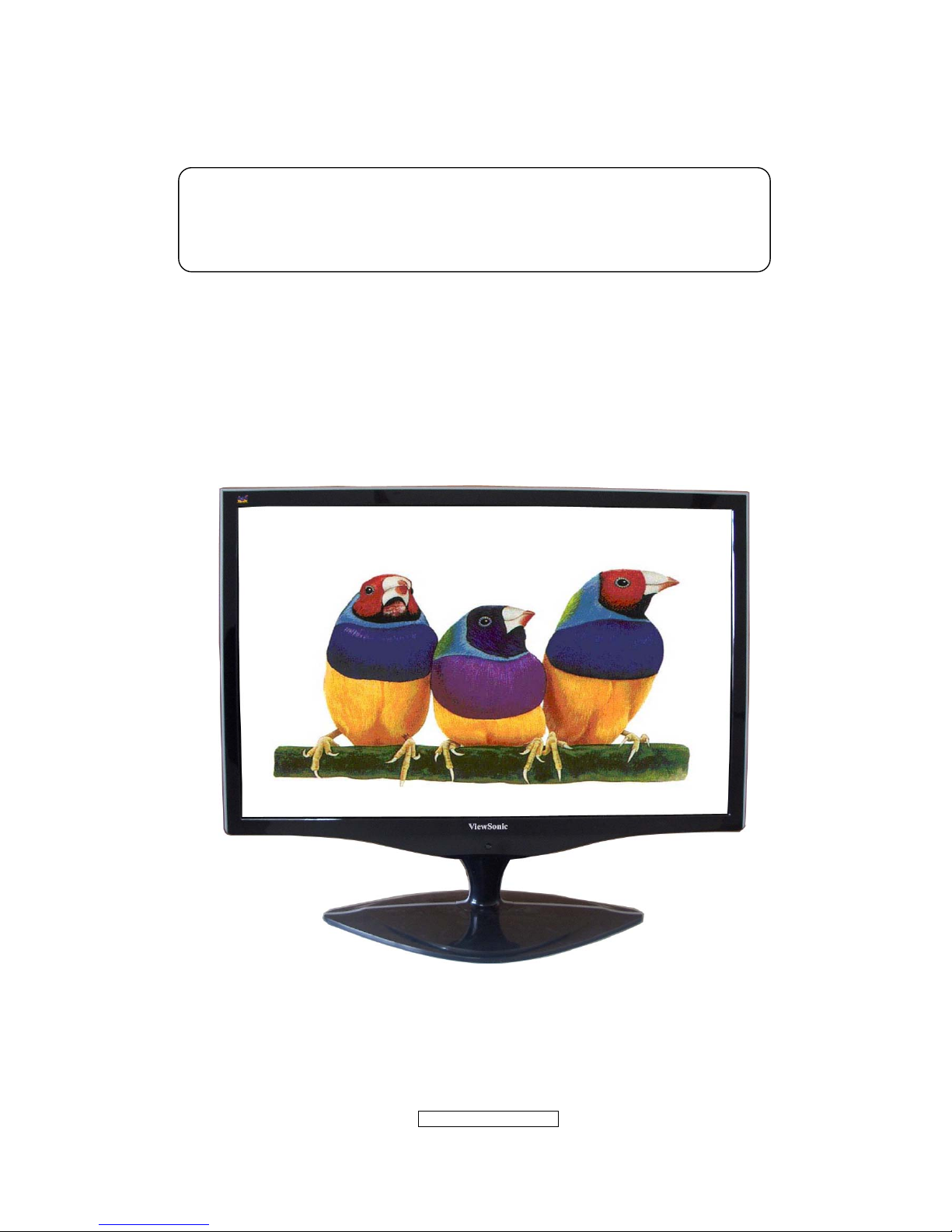
ViewSonic VX2262WM - 22"" LCD Monitor, VX2262WMP, VS12132 Service Manual
- 1 –
ViewSonic Corporation
Confidential - Do Not Cop VX2262wm/wmp
Manufacture Date: Apr-24-08
Service Manual
ViewSonic VX2262wm/wmp
Model No VS12132
22” Color TFT LCD Display
- 2 –
ViewSonic Corporation
Confidential - Do Not Cop VX2262wm/wmp
Copyright Information
Copyright © ViewSonic
®
Corporation, 2006. All rights reserved.
Macintosh and Power Macintosh are registered trademarks of Apple Computer, Inc.
Microsoft, Windows, Windows NT, and the Windows logo are registered trademarks of
Microsoft Corporation in the United States and other countries.
ViewSonic, the three birds logo, OnView, ViewMatch, and ViewMeter are registered
trademarks of ViewSonic Corporation.
VESA is a registered trademark of the Video Electronics Standards Association. DPMS
and DDC are trademarks of VESA.
ENERGY STAR
®
is a registered trademark of the U.S. Environmental Protection Agency
(EPA). As an ENERGY STAR
®
partner, ViewSonic Corporation has determined that this
product meets the ENERGY STAR
®
guidelines for energy efficiency.
Disclaimer: ViewSonic Corporation shall not be liable for technical or editorial errors or
omissions contained herein; nor for incidental or consequential damages resulting from
furnishing this material, or the performance or use of this product.
In the interest of continuing product improvement, ViewSonic Corporation reserves the
right to change product specifications without notice. Information in this document may
change without notice.
No part of this document may be copied, reproduced, or transmitted by any means, for any
purpose without prior written permission from ViewSonic Corporation.
Copyright © ViewSonic
®
Corporation, 2006. All rights reserved. No part of this publication
may be reproduced, transmitted, transcribed, stored in a retrieval system, or translated into
any language or manual or otherwise, without the prior written permission of ViewSonic
®
Corporation.
Revision History
Revision Date Description of changes Approval
A01 Apr-24-08
Initial Release
(TC8MM8MKWHVSD1J)
YG.WANG
- 3 –
ViewSonic Corporation
Confidential - Do Not Cop VX2262wm/wmp
TABLE OF CONTENTS
1. Precautions And Safety Notices 4
2. Specification 7
3. Front Panel Control And Indicators 10
4. Circuit Description 17
5. Adjustment Procedure 25
6. Troubleshooting Flow Chart 43
7. Recommended Spare Parts List 44
8. Exploded Diagram And Spare Parts List 60
9. Disassemble Process 64
10. Block Diagram 68
11. Schematic Diagram 69
12. PCB Layout Diagram 77

- 4 –
ViewSonic Corporation
Confidential - Do Not Cop VX2262wm/wmp
1. Precautions And Safety Notices
1.1 SAFETY PRECAUTIONS
This monitor is manufactured and tested on a ground principle that a user’s safety comes
first. However, improper use or installation may cause damage to the monitor as well as
the user. Carefully go over the following WARNINGS before installing and keep this guide
handy.
WARNINGS
.This monitor should be operated only at the correct power sources indicated on the label
on the rear end of the monitor. If you’re unsure of the power supply in your residence,
consult you local dealer or power company.
.Use only the special power adapter that comes with this monitor for power input.
.Do not try to repair the monitor your self as it contains no user-serviceable parts. This
monitor should only be repaired by a qualified technician.
.Do not remove the monitor cabinet. There is high-voltage parts inside that may cause
electric shock to human bodies, even when the power cord is unplugged.
.Stop using the monitor if the cabinet is damaged. Have it checked by a service technician.
.Put your monitor only in a clean, dry environment. If it gets wet, unplug the power cable
immediately and consult your service technician.
.Always unplug the monitor before cleaning it .Clean the cabinet with a clean, dry cloth.
Apply non-ammonia based cleaner onto the cloth, not directly onto the glass screen.
.Keep the monitor away from magnetic objects, motors, TV sets, and transformer.
.Do not place heavy objects on the monitor or power cord.
1.2 PRODUCT SAFETY NOTICE
Many electrical and mechanical parts in this chassis have special safety visual inspections
and the protection afforded by them cannot necessarily be obtained by using replacement
components rated for higher voltages, wattage, etc. Before replacing any of these
components read the parts list in this manual carefully. The use of substitute replacement
parts which do not have the same safety characteristics as specified in the parts list may
create shock, fire ,or other hazards.
1.3 SERVICE NOTES
1. When replacing parts or circuit boards, clamp the lead wires around terminals before
soldering.
2. When replacing a high wattage resistor(more than 1W of metal oxide film resistor) in
circuit board, keep the resistor about 5mm away from circuit board.
3. Keep wires away from high voltage, high temperature components and sharp edges.
4. Keep wires in their original position so as to reduce interference.
5. Usage of this product please refer to also user’s manual.
- 5 –
ViewSonic Corporation
Confidential - Do Not Cop VX2262wm/wmp
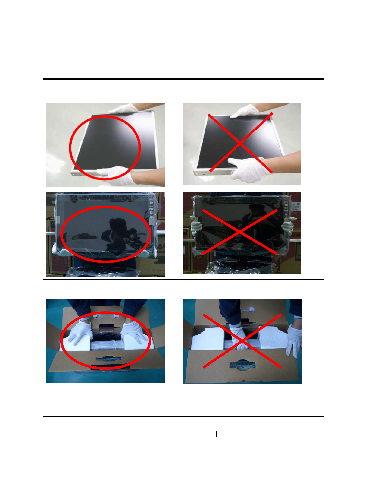
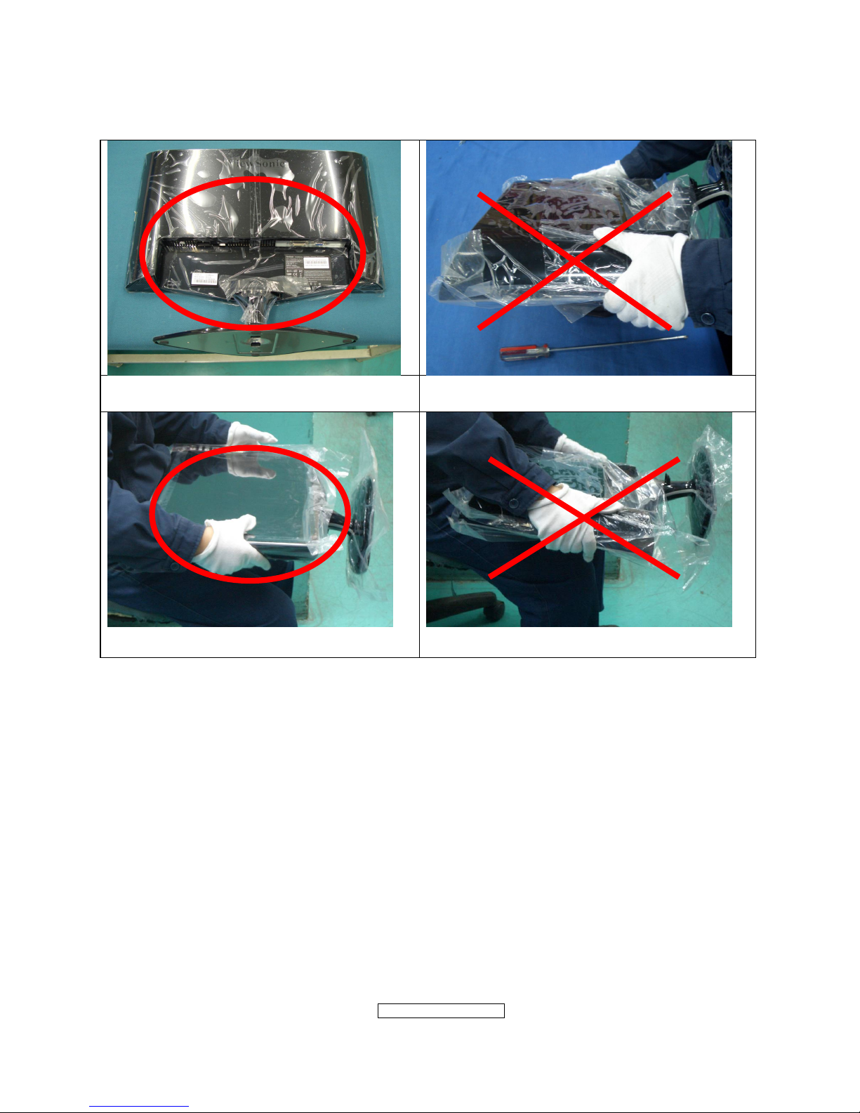
1.4 HANDING AND PLACING METHODS
Correct Methods: Incorrect Methods:
Only touch the metal frame of the LCD
panel or the front cover of the monitor. Do
not touch the surface of the polarizer.
Surface of the LCD panel is pressed by fingers
and that may cause “Mura.”
Take out the monitor with cushions
Taking out the monitor by grasping the LCD
panel. That may cause “Mura.”
Place the monitor on a clean and soft foam
pad.
Placing the monitor on foreign objects. That
could scratch the surface of the panel or cause
“Mura.”
- 6 –
ViewSonic Corporation
Confidential - Do Not Cop VX2262wm/wmp
Place the monitor on the lap, the panel
surface must be upwards.
The panel is placed facedown on the lap. That
may cause “Mura.”
- 7 –
ViewSonic Corporation
Confidential - Do Not Cop VX2262wm/wmp
2. Specification
2.1 PRODUCT SPECIFICATIONS
Type
22” (full 22” wide viewable diagonal area),
TFT(Thin Film Transistor), Active Matrix WXGA+LCD,
0.282mm pixel pitch
Color Filter RGB vertical stripe
LCD
Glass Surface Anti-Glare
Input Signal Video Sync RGB analog(0.7/1.0 Vp-p, 75ohms)/TMDS Digital(100ohms)
Composite Sync, Separate Sync, Sync on Green
Fh:24-83 kHz, Fv:50-76 Hz
Compatibility PC
Macintosh
Up to 1680 x 1050 Non-interlaced
Power Macintosh up to 1680 x 1050
Resolution Recommended
and supported
1680 x 1050 @ 60 Hz
1440 x 900 @ 60, 75 Hz
1280 x 1024 @ 60, 75 Hz
1024 x768 @ 60, 70, 72, 75 Hz
800 x 600 @ 56, 60, 72, 75 Hz
640 x 480 @ 60, 75 Hz
720 x 400 @ 70 Hz
Power Voltage 100V~240 VAC, 50/60Hz (auto switch)
Display area Full Scan
473.76mm(H) x 296.1mm(V)
18.65”(H) x 11.66”(V)
Operating
conditions
Temperature
Humidity
Altitude
32°F to + 104°F( 0°C to + 40°C)
10%C to + 90%(non-condensing)
To 10,000 feet
Storage
conditions
Temperature
Humidity
Altitude
-4°F to + 140°F( -20°C to + 60°C)
10%C to + 90%(non-condensing)
To 40,000 feet
Dimensions Physical
508.7mm(W) x 440.55mm(H) x 202.84mm(D)
20.02”(W) x 17.34”(H) x 7.98”(D)
Weight Physical 12.23 Ib(5.56 kg)
Regulations
BSMI, VCCI,CCC, PSB, C-Tick, MIC, CE, Gost-R/Hygienic,
Ukraine, MPRII, ISO13406-2, SASO, TUVdotcom, UL/cUL,
FCC-B, ICES-B, TUV-S/IRAM/UL-AR S Mark, NOM,
E
NERGY STAR
®
Power saving
modes
On
Off
45W (Typical) (blue LED)
<1W
Preset Timing Mode (pre-adjusted to VESA® 1680 x 1050 @ 60 Hz)
Warning: Do not set the graphics card in your computer to exceed these refresh rates; doing so
may result in permanent damage to the LCD display.
1
Macintosh computers older than G3 require a ViewSonic® Macintosh adapter. To order an
adapter, contact ViewSonic.
- 8 –
ViewSonic Corporation
Confidential - Do Not Cop VX2262wm/wmp
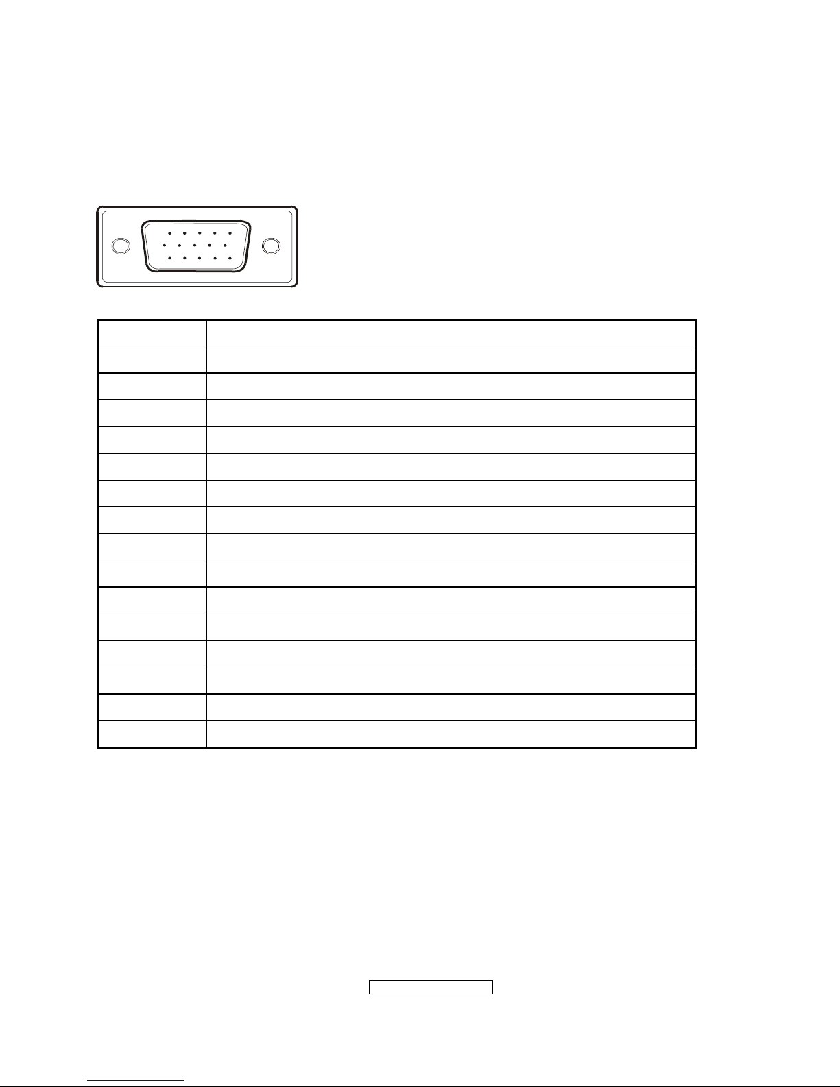
2.2 INTERFACE DESCRIPTION
D-SUB 15 PIN CONNECTOR
15
6
10
11 15
Pin Number Pin Function
1 Red video input
2 Green video input
3 Blue video input
4 No Connection
5 Ground
6 Red video ground
7 Green video ground
8 Blue video ground
9 +5V
10 H/V sync ground
11 No connection
12 (SDA)
13 Horizontal sync (Composite sync)
14 Vertical sync
15 (SCL)
- 9 –
ViewSonic Corporation
Confidential - Do Not Cop VX2262wm/wmp
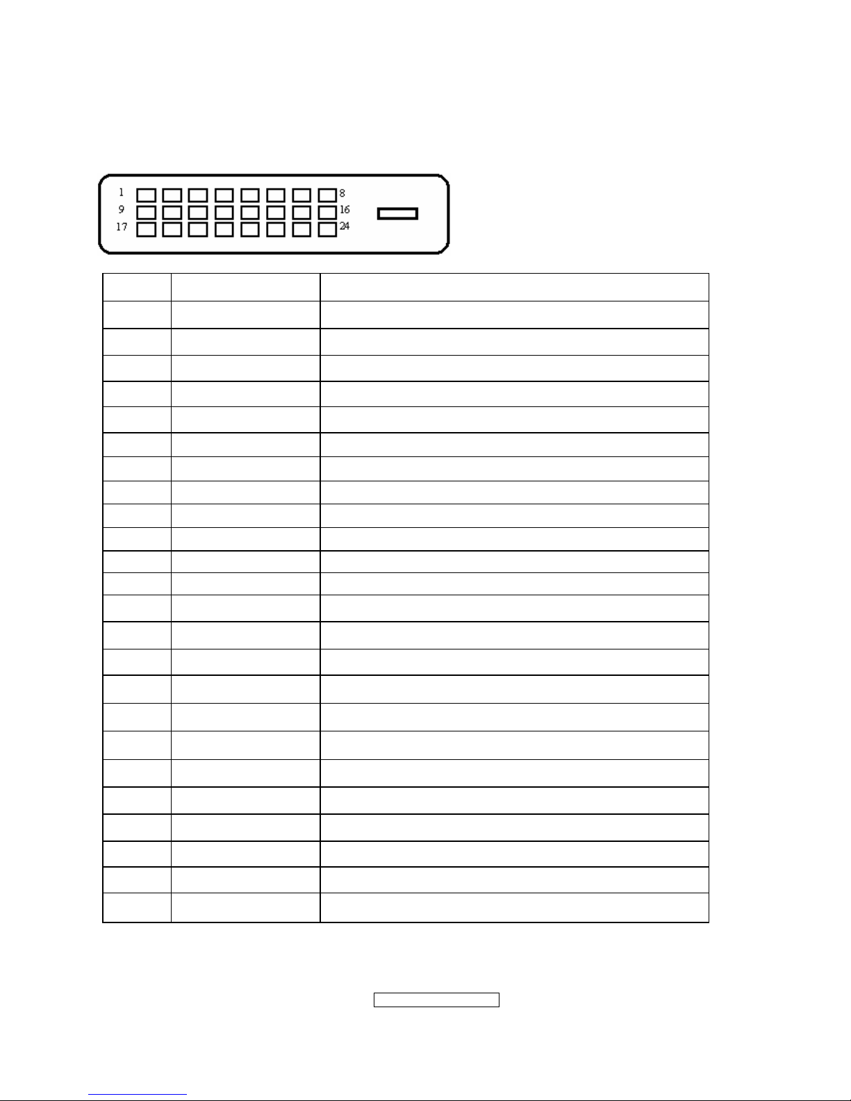
DVI-D 24 PIN CONNECTOR
Pin No. Signal Name Description
1 RX2- TMDS negative differential input, channel 2
2 RX2+ TMDS positive differential input, channel 2
3 GND Logic Ground
4 Reserved 4 Reserved. No connection
5 Reserved 5 Reserved. No connection
6 DDC-CLK DDC2B Clock
7 DDC-DAT DDC2B Data
8 Reserved 8 Reserved. No connection
9 RX1- TMDS negative differential input, channel 1
10 RX1+ TMDS positive differential input, channel 1
11 GND Logic Ground
12 Reserved 12 Reserved. No connection
13 Reserved 13 Reserved. No connection
14 VCCX Power
15 GND Logic Ground
16 SENS SENSE Pin, Pull High
17 RX0- TMDS negative differential input, channel 0
18 RX0+ TMDS positive differential input, channel 0
19 GND Logic Ground
20 Reserved 20 Reserved. No connection
21 Reserved 21 Reserved. No connection
22 GND Logic Ground
23 RXC+ TMDS positive differential input, reference clock
24 RXC- TMDS negative differential input, reference clock
- 10 –
ViewSonic Corporation
Confidential - Do Not Cop VX2262wm/wmp
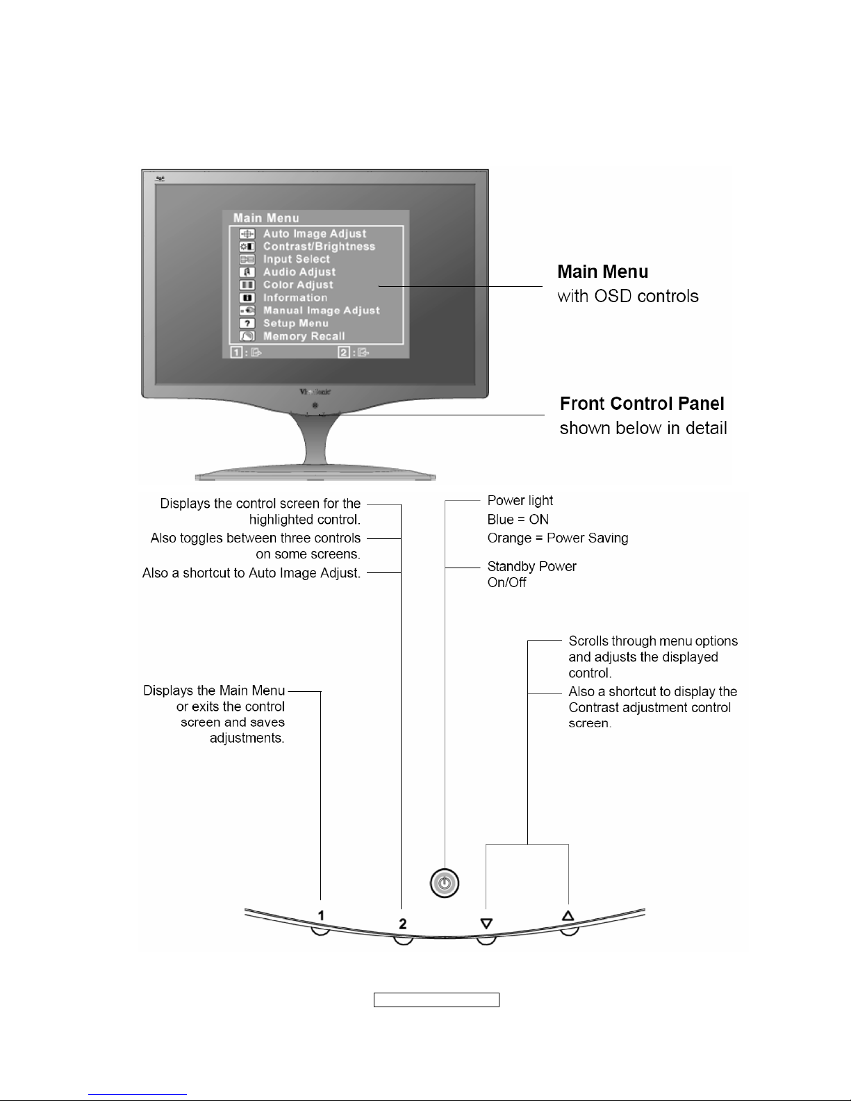
3. Front Panel Function Controls And Indicators
- 11 –
ViewSonic Corporation
Confidential - Do Not Cop VX2262wm/wmp
Do the following to adjust the display setting:
1. To display the Main Menu, press button [1].
NOTE: All OSD menus and adjustment screens disappear automatically after about 15
seconds. This is adjustable through the OSD timeout setting in the setup menu.
2. To select a control to adjust, press ▲or ▼ to scroll up or down in the Main Menu.
3. After the desired control is selected, press button [2]. A control screen like the one
shown below appears.
The line at the bottom of the screen
shows the current functions of
buttons 1 and 2: Exit or select the
Brightness control.
4. To adjust the control, press the up ▲ or▼ down buttons.
5. To save the adjustments and exit the menu, press button [1] twice.
The following tips may help you optimize your display:
• Adjust the computer's graphics card so that it outputs a 1680 x 1050 @ 60Hz video
signal to the LCD display. (Look for instructions on “changing the refresh rate” in the
graphics card's user guide.)
• If necessary, make small adjustments using H. POSITION and V. POSITION until the
screen image is completely visible
. (The black border around the edge of the screen
should barely touch the illuminated “active area” of the LCD display.)
- 12 –
ViewSonic Corporation
Confidential - Do Not Cop VX2262wm/wmp
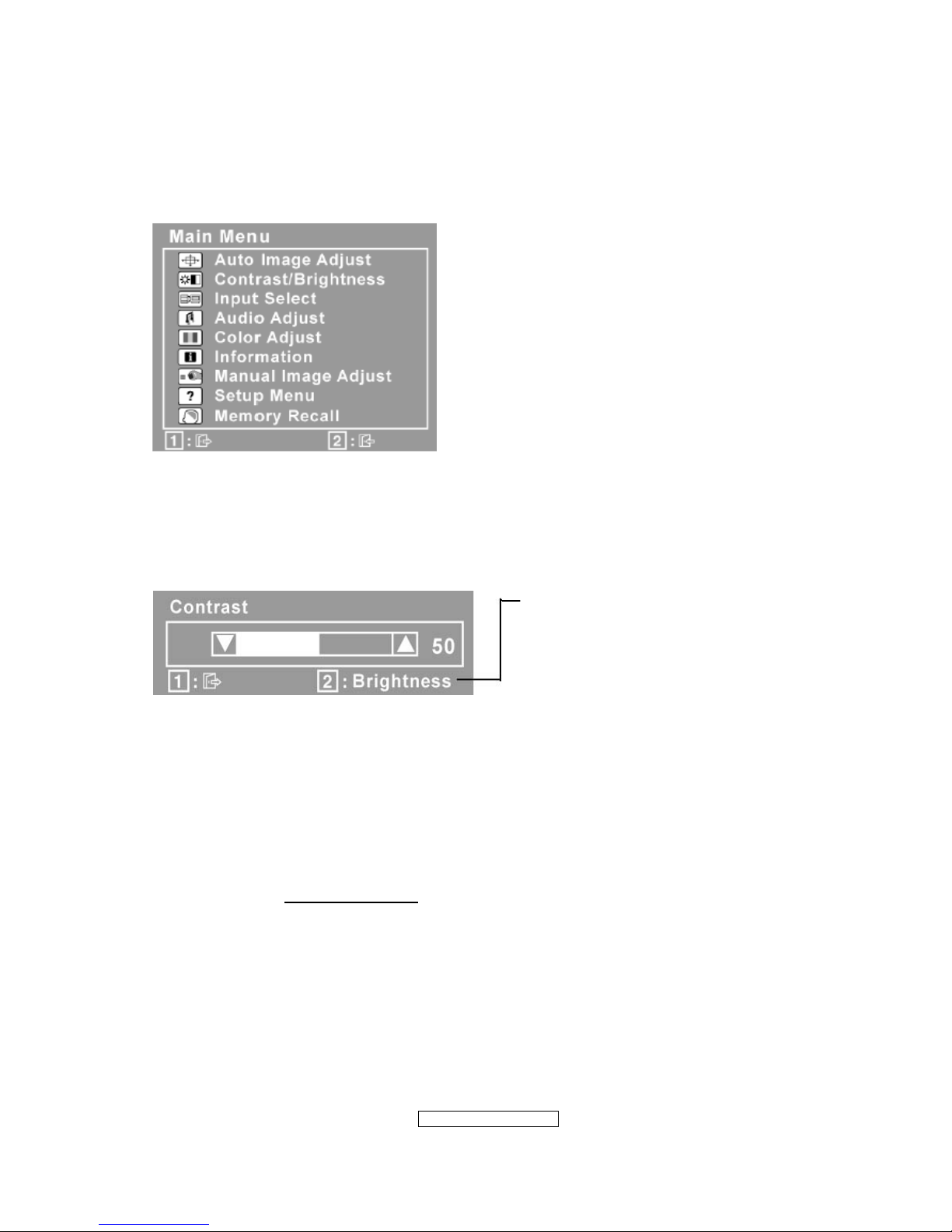
Main Menu Controls
Adjust the menu items shown below by using the up
and down buttons.
Control
Explanation
Auto Image Adjust automatically sizes, centers, and fine tunes the video
signal to eliminate waviness and distortion. Press the [2] button to obtain a
sharper image.
NOTE: Auto Image Adjust works with most common video cards. If this
function does not work on your LCD display, then lower the video refresh rate
to 60 Hz and set the resolution to its pre-set value.
Contrast adjusts the difference between the image background (black level)
and the foreground (white level).
Brightness adjusts background black level of the screen image.
Input Select toggles between inputs if you have more than one computer
connected to the LCD Display.
Audio Adjust
Volume increases the volume, decreases the volume, and mutes the audio.
Mute temporarily silences audio output.
Color Adjust provides several color adjustment modes, including preset color
temperatures and a User Color mode which allows independent adjustment of
red (R), green (G), and blue (B). The factory setting for this product is 6500K
(6500 Kelvin).
sRGB-This is quickly becoming the industry standard for color management,
with support being included in many of the latest applications. Enabling this
setting allows the LCD display to more accurately display colors the way they
were originally intended. Enabling the intended. Enabling the sRGB setting
will cause Contrast and Brightness adjustments to be disabled.
- 13 –
ViewSonic Corporation
Confidential - Do Not Cop VX2262wm/wmp
9300K-Adds blue to the screen image for cooler white (used in most office
settings with fluorescent lighting).
7500K-Adds blue to the screen image for cooler white(used in most office
settings with fluorescent lighting).
6500K-Adds red to the screen image for warmer white and richer red.
5000K-Adds green to the screen image for a darker color.
User Color Individual adjustments for red (R), green (G), and blue (B).
1. To select color (R, G or B) press button [2].
2. To adjust selected color, press
▲ and▼.
Important: If you select RECALL from the Main Menu when the product is
set to a Preset Timing Mode, colors return to the 6500K factory preset.
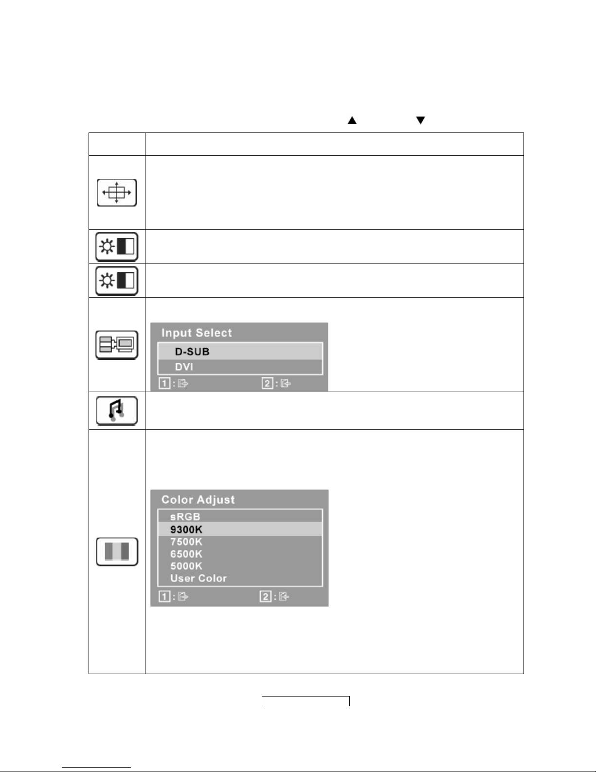
Information displays the timing mode (video signal input) coming from the
graphics card in the computer, the LCD model number, the serial number, and
the ViewSonic
®
website URL. See your graphics card’s user guide for
instructions on changing the resolution and refresh rate (vertical frequency).
NOTE: VESA 1680 x 1050 @ 60Hz (recommended) means that the resolution
is 1680 x 1050 and the refresh rate is 60 Hertz.
Manual Image Adjust display the Manual Image Adjust menu
H./V. Position (Horizontal/Vertical Position) moves the screen image left or
right and up or down.
H. Size (Horizontal Size) adjusts the width of the screen image.
- 14 –
ViewSonic Corporation
Confidential - Do Not Cop VX2262wm/wmp
Fine Tune sharpens the focus by aligning text and/or graphics with pixel
boundaries.
NOTE: Try Auto Image Adjust first.
Sharpness adjusts the clarity and focus of the screen image.
Dynamic Contrast allows the user to turn the contrast ratio enhancement on
or off.
Aspect ratio Selects the image size for 4:3, fill aspect ratio & full screen.
Response Time adjusts the response time of liquid-crystal display for image
quality enhancement.
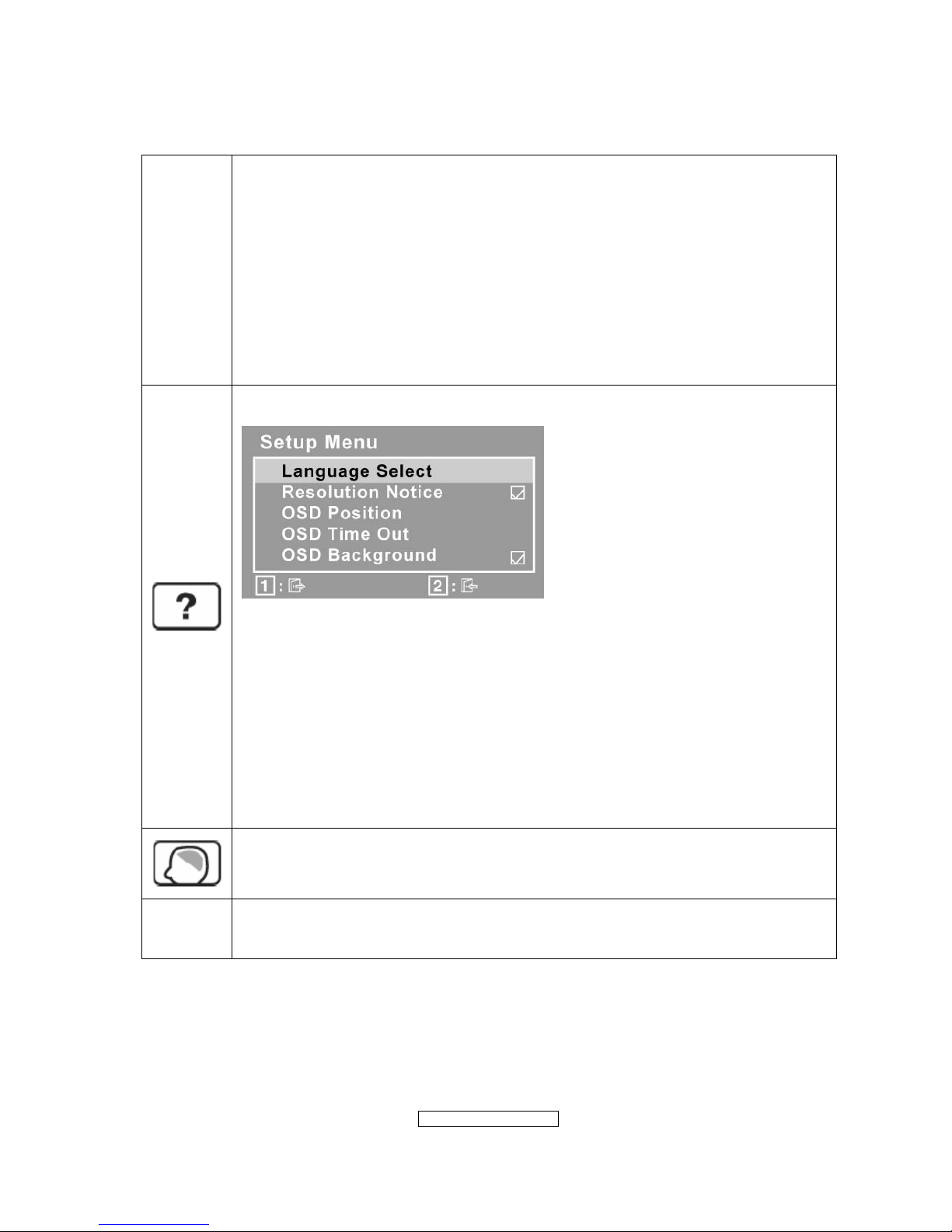
Setup Menu displays the menu shown below:
Language Select allows the user to choose the language used in the menus
and control screens.
Resolution Notice advises the optimal resolution to use.
OSD Position allows the user to move the OSD menus and control screens.
OSD Timeout sets the length of time the OSD screen is displayed. For
example, with a “15 second” setting, if a control is not pushed within 15
seconds, the display screen disappears.
OSD Background allows the user to turn the OSD background On or Off.
Memory Recall returns the adjustments back to factory settings if the display
is operating in a factory Preset Timing Mode listed in the Specifications of this
manual.
Exception: This control does not affect changes made with the User Color
control, Language Select or Power Lock setting.
- 15 –
ViewSonic Corporation
Confidential - Do Not Cop VX2262wm/wmp
SHORT CUTS FUNCTION FROM THE BUTTONS
[1]
Main Menu
[2]
Input toggle (D-sub/DVI); refer to Appendix D)
[▼]
To immediately activate Audio menu.
[▲]
To immediately activate Contrast menu. It should be change
to Brightness OSD by push button [2]
*1 refer to the Brightness OSD
*2 Under sRGB or DCR mode, this function is disabled.
[▼] + [▲]
1. In the CR/ BT menu, Recall both of Contrast and
Brightness to default without OSD message.
2. In the Audio menu, Recall both of audio volume and mute
to default without OSD message.
[1] + [2]
1. Toggle 720x400 and 640x400 mode when input 720x400
or 640x400 mode.
2. Toggle 1400x1050 and 1680x1050 mode when input
1400x1050 or 1680x1050mode.
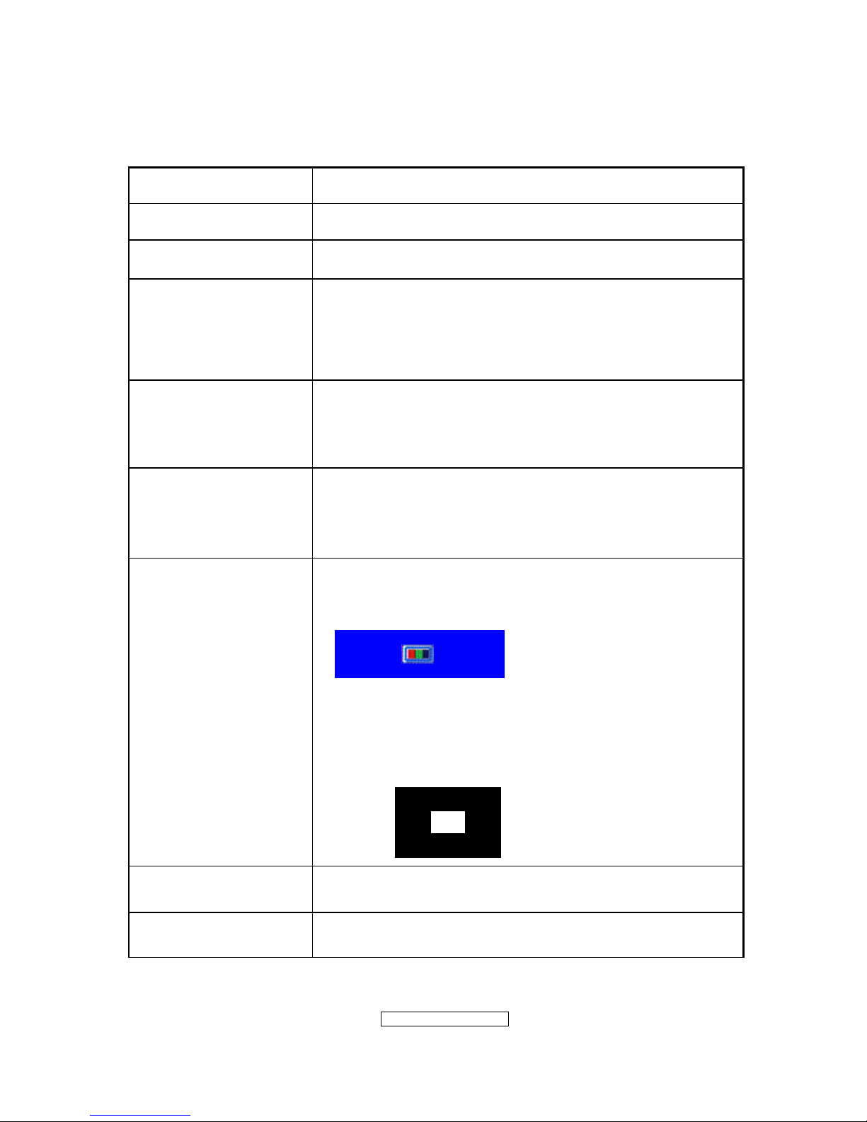
[1] + [▼] + [▲]
(Keep pushing 5 sec)
White Balance
1. It will not shown on user’s guide
2. OSD message as below,
(Image = no blanking)
3. Recommend environment
3.1. Optical (Best) input timing = 640 x 480 @ 60Hz;
Following timing modes also recommended,
800 x 600 @ 60 Hz
1024 X 768 @ 60 Hz
3.2. Pattern as below,
[1] + [▲]
OSD Lock / Unlock
[1] + [▼] Power Lock / Unlock
- 16 –
ViewSonic Corporation
Confidential - Do Not Cop VX2262wm/wmp
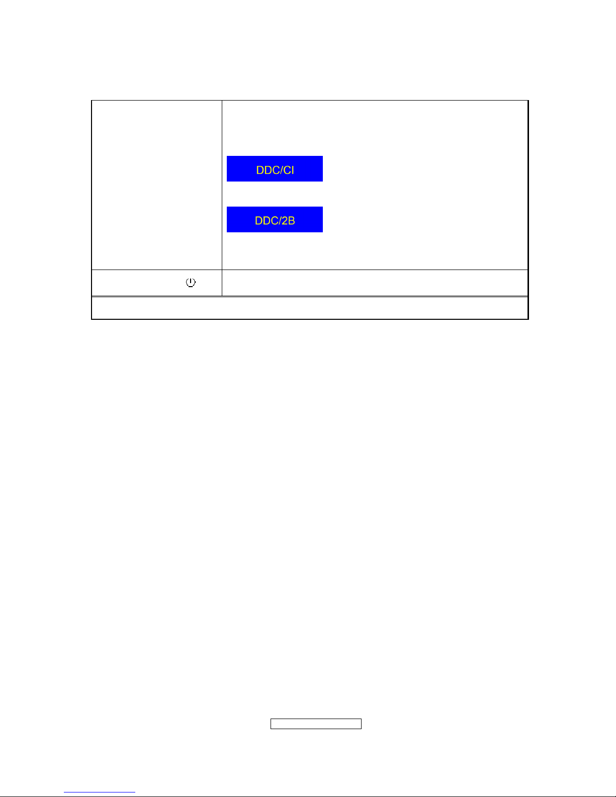
[2] + [▼]
Toggle DDC/CI and DDC/2B (DDC/CI enable/disable) and
show following message for 3 seconds,
When switch to DDC/CI
When switch to DDC/2B
Default = DDC/CI
Signal + [2] + [ ] Factory Mode
Remark : All the short cuts function are only available while OSD off
- 17 –
ViewSonic Corporation
Confidential - Do Not Cop VX2262wm/wmp
4. Circuit Description
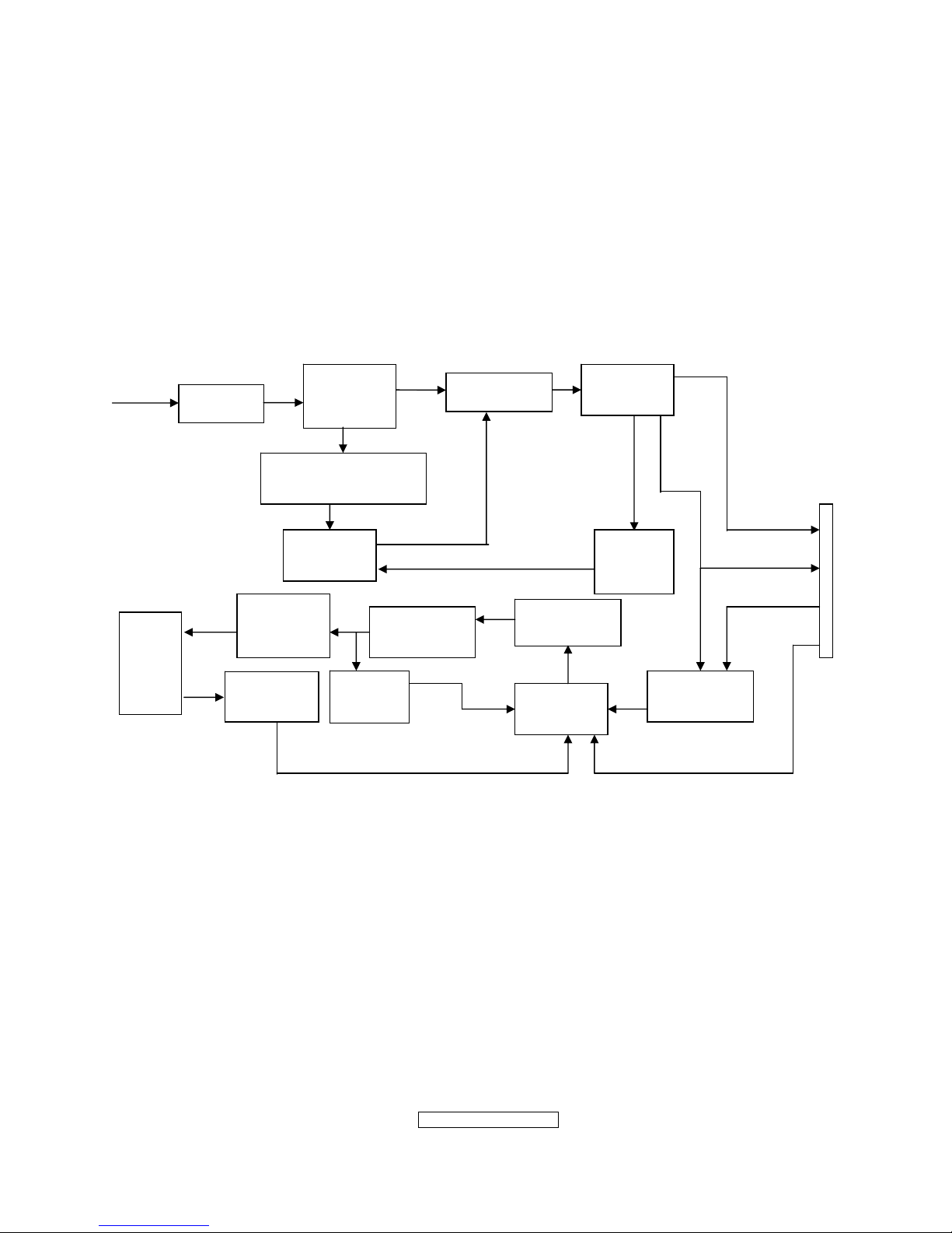
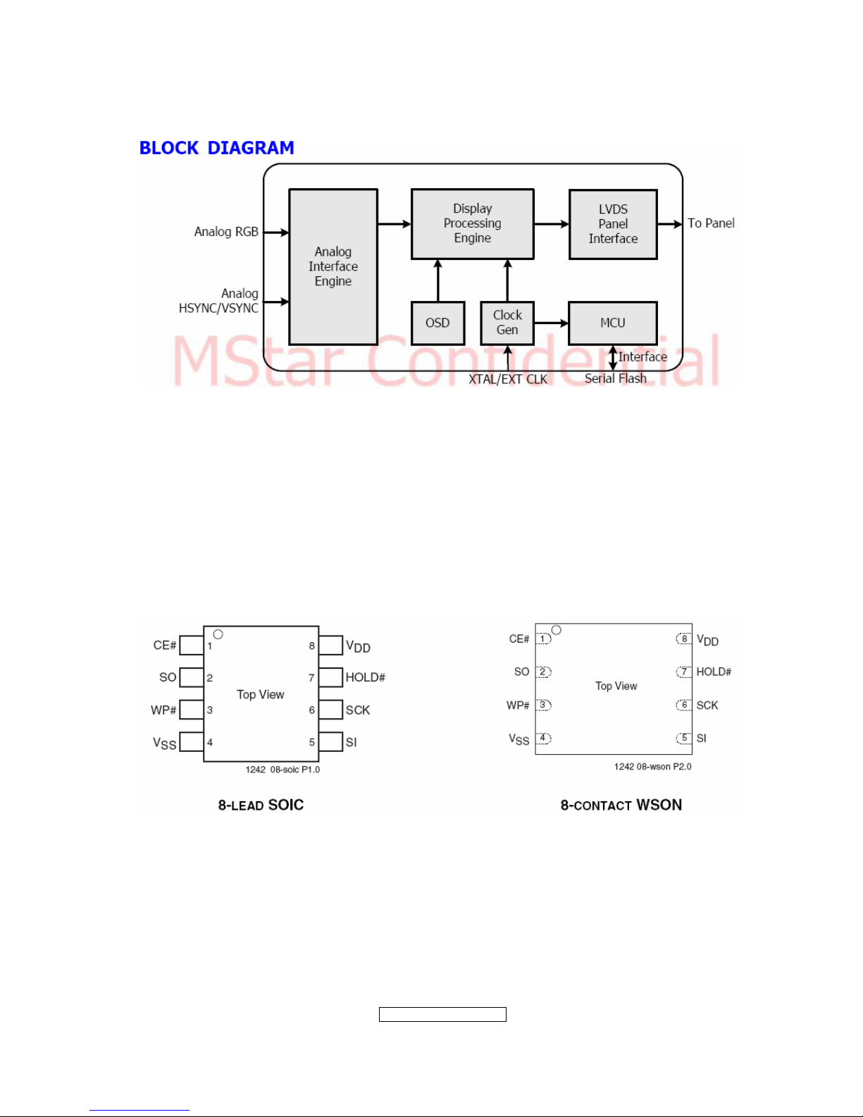
4.1 LCD MONITOR DESCRIPTION
The LCD MONITOR will contain a Main Board, an Power Board, Key Board which
house the flat panel control logic, brightness control logic and DDC.
4.2 MAIN BOARD BLOCK FUNCTION DESCRIPTION
The main board contains panel control logic, brightness control logic, DDC and DC
convert DC circuit and so on.
Power Board
(Include: adapter, inverter)
Flat Panel and
CCFL backlight
Main Board
Key Board
RS232 Connector
For white balance
adjustment in factory
mode
HOST Computer
CCFL Drive.
AC-IN
100V-240V
Video signal, DDC
Monitor Block Diagram
R
G
B
H
V
SDA
SCL
OSC
Backlight and Panel
PWPC board
Flash memory
Keyboard
TSUMO58CWHL-LF
- 18 –
ViewSonic Corporation
Confidential - Do Not Cop VX2262wm/wmp
4.3 PWPC BOARD BLOCK FUNCTION DESCRIPTION
PWPC board combines to adapter and inverter, Adapter which commonly consists
of bridge rectifier and filter, start circuit, PWM control circuit, protection circuits and
convert to 16V, 5V,5.1V DC voltage by input 90V-240V AC voltage that provide power
supply for each chips in the main board and inverter. Inverter is DC TO AC circuit. It
changes the 16v DC of power supply to about 600-800v AC that drives the backlight. It
mostly consists of starting circuit, PWM controller, DC changing circuit, LC surging
circuit, output circuit and protection circuit etc.
AC input
EMI filter
Bridge
Rectifier
and Filter
Start Circuit
R904, R905, R906
PWM
Control IC
Over
Voltage
Protect
Rectifier
CMOS
ON/OFF
Control
PWM
Control IC
Feedback
Circuit
OSC and
Output
Circuit
DC Convert
Circuit
MOSFET
Q804,Q809
Over
Voltage
CN902
Transformer
Lamp
5V
5.1V
ON/OF
DIM
16V
- 19 –
ViewSonic Corporation
Confidential - Do Not Cop VX2262wm/wmp
4.4 INTRODUCTION OF IC
TSUMO58CWHL-LF(U401): integrate ADC, OSD, SCALER, MCU, LVDS, convert
analog RGB into digital and room and shrink scaling output to LCD panel.
PIN Function:
Pin Symbol Description
41 SDO SPI flash serial data output
42 CSZ SPI flash chip select
43 SCK SPI flash serial select
44 SDI SPI flash serial data input
34 DDCA_SDA/RS232_TX DDC Data for analog interface/
UART Ttransmitter /
General Purpose Input/Output;
4mA driving strength
35 DDCA_SCL/RS232_RX DDC Clock for analog interface/
UART Receiver /
General Purpose Input/Output;
4mA driving strength
5 DDCD_SDA DDC Data and HDCP Slave Serial
Port Data for DVI/HDMI Interface;
4mA driving strength
6 DDCD_SCL DDC Clock and HDCP Slave
Serial Port Data for DVI/HDMI
Interface
102 BYPASS For External Bypass Capacitor
108 RST Chip reset; High reset
103 VCTRL Regulator control
32 HSYNCO Analog HSYNC input
33 VSYNCO Analog VSYNC input
31 REFP Internal ADC top de-coupling pin
30 REFM Internal ADC bottom de-coupling
pin
7 REXT External resistor 390 ohm to
AVDD_33
37 MODE Chip Configuration Input; 10K
ohm pull-low for normal operation
128 XIN Xin; Crystal Oscillator Input
127 XOUT Xout; Crystal Oscillator Output
8,12,20
AVDD_33
ADC Analog Power 3.3V
21
AVDD_18
ADC Analog Power 1.8V
40,54,58-60,65,66,71,87,107
112,114
VDDP Digital Output Power 3.3V
53,74,104,126 VDDC Digital Core Power 1.8V
1,11,17,29,52,62,63,68,69,72,
88,101,105,106,113
GND Ground
- 20 –
ViewSonic Corporation
Confidential - Do Not Cop VX2262wm/wmp
- 21 –
ViewSonic Corporation
Confidential - Do Not Cop VX2262wm/wmp
AP1117D33LA(701): DC power convert, convert to 3.3v.
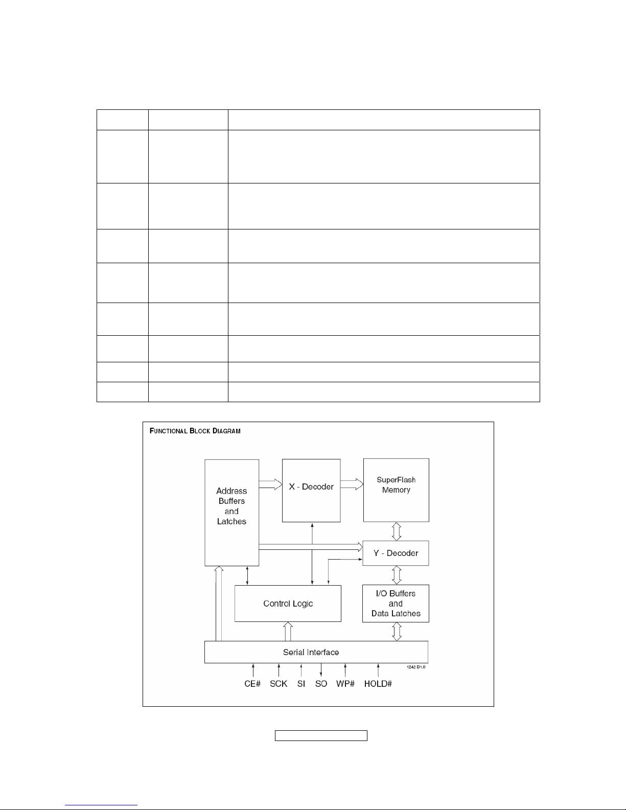
SST25LF020A-33-4C-SAE(U402): SST’s serial flash family features a four-wire,
SPI-com-patible interface that allows for a low pin-count package occupying less board
space and ultimately lowering total system costs. The SST25LF020A/040A devices
significantly improve performance, while lowering power consumption. The total energy
consumed is a function of the applied voltage, current, and time of application. The
SST25LF020A/040A devices operate with a single 3.0-3.6V power supply. The
SST25LF020A devices are offered in an 8-lead SOIC 150 mil body width (SA) package.
Pin Diagram:
PIN Descriptions:
- 22 –
ViewSonic Corporation
Confidential - Do Not Cop VX2262wm/wmp
Circuit Diagram
Symbol Pin Name Functions
SCK Serial Clock
To provide the timing of the serial interface.
Commands, addresses, or input data are latched on the
rising edge of the clock input, while output data is shifted out
on the falling edge of the clock input.
SI
Serial Data
Input
To transfer commands, addresses, or data serially into the
device.
Inputs are latched on the rising edge of the serial clock.
SO
Serial Data
Output
To transfer data serially out of the device.
Data is shifted out on the falling edge of the serial clock.
CE# Chip Enable
The device is enabled by a high to low transition on CE#.
CE# must remain low for the duration of any command
sequence.
WP# Write Protect
The Write Protect (WP#) pin is used to enable/disable BPL
bit in the status register.
HOLD# Hold
To temporarily stop serial communication with SPI flash
memory without resetting the device.
VDD Power Supply To provide power supply(3.0-3.6V)
VSS Ground
- 23 –
ViewSonic Corporation
Confidential - Do Not Cop VX2262wm/wmp
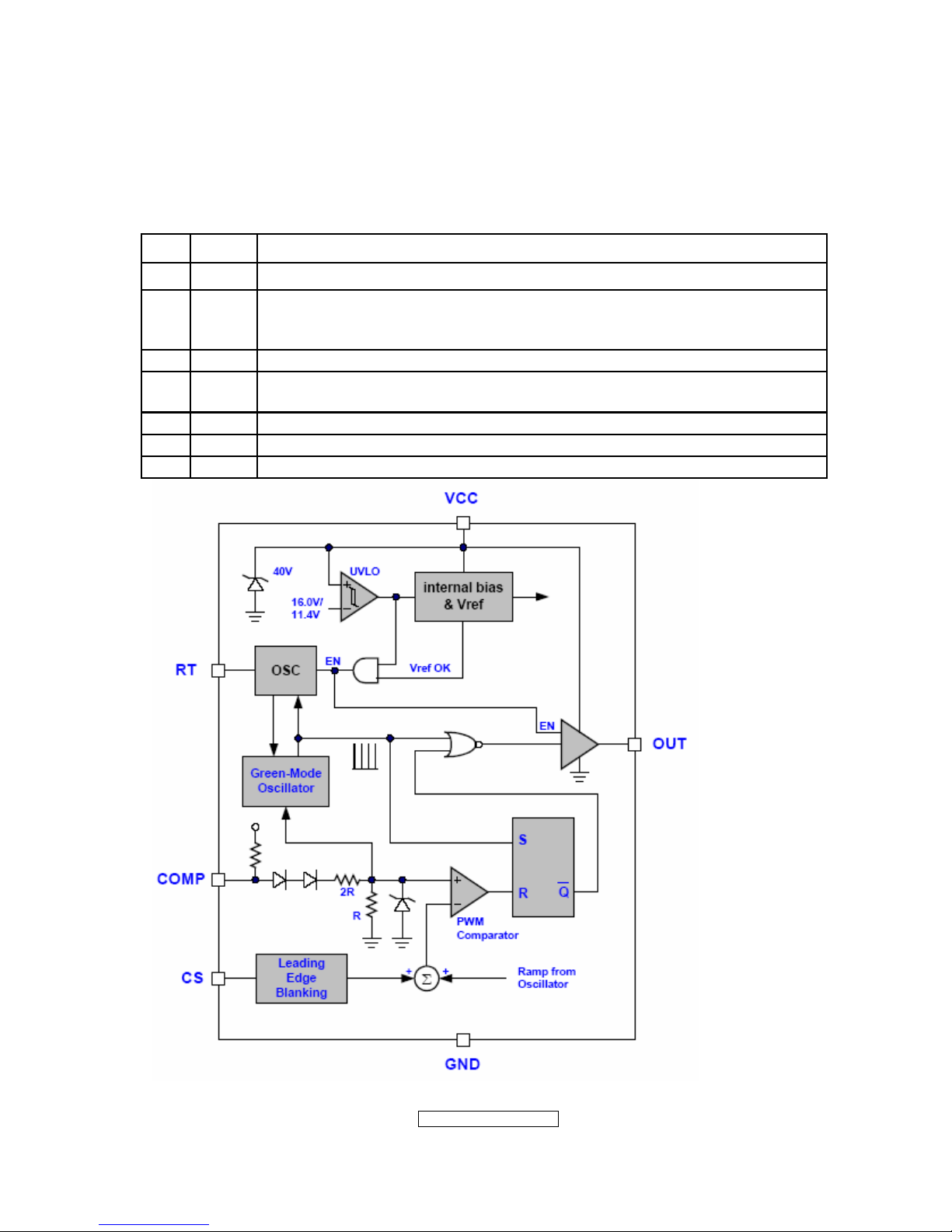
LD7552DPS (IC901): PWM control, high-voltage startup current. The circuit unit has
functions such as over-current protection, over-voltage protection, output short-circuit
protection and etc. The function of each pin and the inside circuit diagram are as
follows:
Pin Name Function
1 GND Ground
2 COMP
Voltage feedback pin (same as the COMP pin in UC384X), By
connecting a photo-coupler to close the control loop and achieve the
regulation
3 VCC Supply voltage pin
4 RT
This pin is to program the switching frequency. By connecting a resistor
to ground to set the switching frequency.
6 NC Unconnected pin
7 VCC Supply voltage pin
8 OUT Gate drive output to drive the external MOSFET
- 24 –
ViewSonic Corporation
Confidential - Do Not Cop VX2262wm/wmp
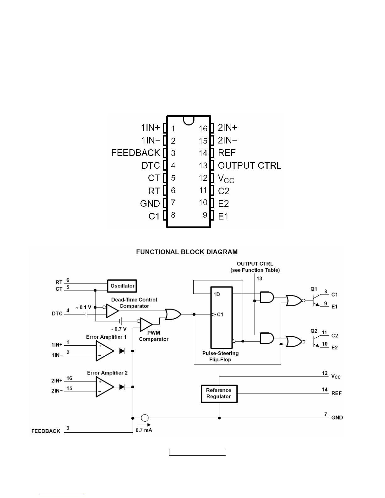
TL494IDR(IC801): The TL494 incorporates all the functions required in the construction
of a pulse-width-modulation (PWM) control circuit on a single chip. Designed
primarily for power-supply control, this device offers the flexibility to tailor the
power-supply control circuitry to a specific application.
PIN Descriptions:

- 25 –
ViewSonic Corporation
Confidential - Do Not Cop VX2262wm/wmp
5. Adjustment Procedure
5.1 ADJUSTMENT CONDITIONS AND PRECAUTIONS
1. Approximately 30 minutes should be allowed for warm up before proceeding.
2. Adjustments should be undertaken only on those necessary elements since most of them
have been carefully preset at the factory.
3. ESD protection is needed before adjustment.
5.2 MAIN ADJUSTMENTS
NO. FUNCTIONS DESIGNATION
1. White Balance Function Key
2. Geometry Function Key
5.3 ALIGNMENT PROCEDURES
Approximately 30 minutes should be allowed for warm up before proceeding
White-Balance adjustment.
1. Adjust of White Balance
1.) How to do the CA-210 MEM .Channel setting
A、Reference to CA-210 user guide
B、Use “ MODE” key to modify x、y、Lv value and use “MEMORY CH” key to modify the
TEXT description Following is the procedure to do white-balance adjust
2.) Setting the color temp. You want
A、MEM.CHANNEL1 ( 9300 color):
9300 color temp. parameter is x = 0.283 ±0.003; y = 0.298 ±0.003;
Lv ≥ 175 cd/m
2 ,
B、MEM.CHANNEL 1 ( 7500 color):
7500 color temp. parameter is x = 0.299±0.003; y = 0.315 ±0.003;
Lv ≥ 188cd/m
2,
C、MEM.CHANNEL1 ( 6500 color):
6500 color temp. parameter is x = 0.313±0.003; y = 0.329 ±0.003;
Lv ≥ 213cd/m
2,
D、MEM.CHANNEL 1 ( 5000 color):
5400 color temp. parameter is x = 0.346±0.003; y = 0.359 ±0.003;
Lv ≥ 175cd/m
2,
E、MEM.CHANNEL1 ( SRGB color):
SRGB color temp. parameter is x=0.313±0.003; y=0.329±0.003; Lv≥85cd/m2,
3.) Into factory mode of VX2262wm/wmp:
First Power off, then press Switch 1 button along with press Power button will activate
the factory mode, then MCU will do AUTO LEVEL automatically. Meanwhile press
MENU the OSD screen will located at LEFT TOP OF PANEL.
 Loading...