

Page 1

Service Manual
ViewSonic VX2240W-4
Model No. VS11985
22” Color TFT LCD Display
(Manufacture date: NOV. 2008)
VX2240W-4
Page 2
1
Copyright
Copyright © 2008 by ViewSonic Corporation. All rights reserved. No part of this publication
may be reproduced, transmitted, transcribed, stored in a retrieval system, or translated into any
language or computer language, in any form or by any means, electronic, mechanical, magnetic,
optical, chemical, manual or otherwise, without the prior written permission of ViewSonic
Corporation.
Disclaimer
ViewSonic makes no representations or warranties, either expressed or implied, with respect to
the contents hereof and specifically disclaims any warranty of merchantability or fitness for any
particular purpose. Further, ViewSonic reserves the right to revise this publication and to make
changes from time to time in the contents hereof without obligation of ViewSonic to notify any
person of such revision or changes.
Trademarks
Optiquest is a registered trademark of ViewSonic Corporation.
ViewSonic is a registered trademark of ViewSonic Corporation.
All other trademarks used within this document are the property of their respective owners.
Product disposal at end of product life
The lamp in this product contains mercury. Please dispose of in accordance with local, state or
federal laws.
Revision History
Revision SM Editing Date ECR Number Description of Changes Editor
Initial Release
TC6MNBDTNWVWN
TC6MNBDTNWVWNND
A01 NOV. 08
TC6MNBHKNWVSN
TC6MNBHKNWVSNND
TC6MNBDDNWVSNNN
TC6MNBDDNWVSNND
Page 3

2
TABLE OF CONTENTS
1. Precautions and Safety Notices..........................................................................................1
2. Specification .......................................................................................................................2
3. Front Panel Function Control Description .......................................................................4
4. Circuit Description .............................................................................................................9
5. Adjusting Procedure..........................................................................................................16
6. Trouble Shooting Flow Chart............................................................................................21
7. Block Diagrams .................................................................................................................22
8. Schematic Diagrams ........................................................................................................23
9. PCB Layout Diagrams ......................................................................................................31
10. Exploded Diagram and Spare Parts List.........................................................................33
11. Recommended Spare Parts List ....................................................................................34
12. Different parts list ...........................................................................................................45
Page 4

1
1. Precautions and Safety Notices
1.1 safety precautions
This monitor is manufactured and tested on a ground principle that a user’s safety comes first. However,
improper use or installation may cause damage to the monitor as well as the user. Carefully go over the
following WARNINGS before installing and keep this guide handy.
WARNINGS
This monitor should be operated only at the correct power sources indicated on the label on the rear end
of the monitor. If you’re unsure of the power supply in your residence, consult you local dealer or power
company.
.Use only the special power adapter that comes with this monitor for power input.
. Do not try to repair the monitor your self as it contains no user-serviceable parts. This monitor should only
be repaired by a qualified technician.
. Do not remove the monitor cabinet. There is high-voltage parts inside that may cause electric shock to
human bodies, even when the power cord is unplugged.
. Stop using the monitor if the cabinet is damaged. Have it checked by a service technician.
. Put your monitor only in a clean, dry environment. If it gets wet, unplug the power cableimmediately and
consult your service technician.
. Always unplug the monitor before cleaning it .Clean the cabinet with a clean, dry cloth. Apply
non-ammonia based cleaner onto the cloth, not directly onto the glass screen.
. Keep the monitor away from magnetic objects, motors, TV sets, and transformer.
. Do not place heavy objects on the monitor or power cord.
1.2 Product safety notice
Many electrical and mechanical parts in this chassis have special safety visual inspections and the
protection afforded by them cannot necessarily be obtained by using replacement components rated for
higher voltages, wattage, etc. Before replacing any of these components read the parts list in this manual
carefully. The use of substitute replacement parts which do not have the same safety characteristics as
specified in the parts list may create shock, fire ,or other hazards.
1.3 Service notes
When replacing parts or circuit boards, clamp the lead wires around terminals before soldering.
When replacing a high wattage resistor(more than 1W of metal oxide film resistor) in circuit board, keep
the resistor about 5mm away from circuit board.
Keep wires away from high voltage, high temperature components and sharp edges.
Keep wires in their original position so as to reduce interference.
Usage of this product please refer to also user’s manual.
Page 5
2
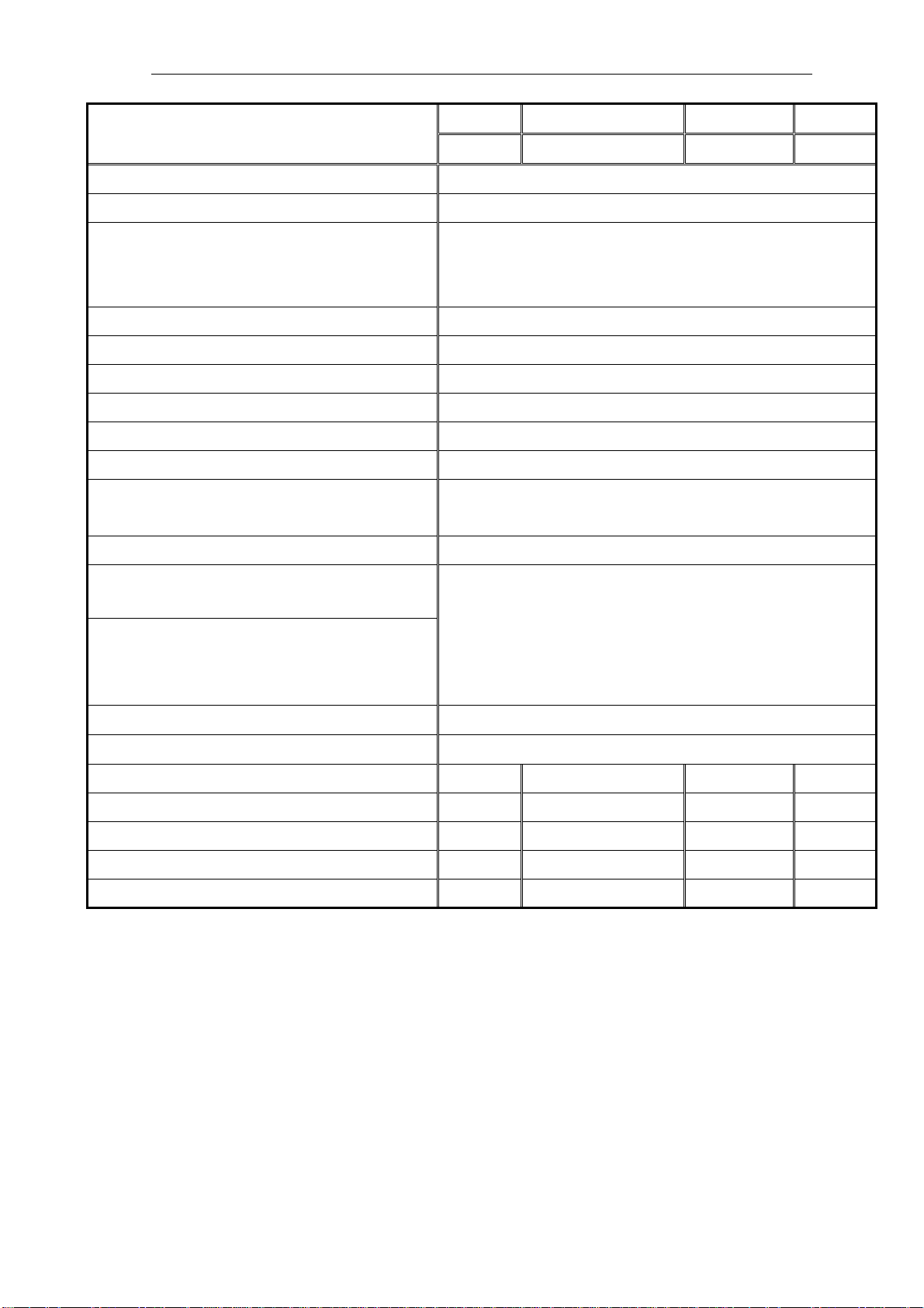
2. Specification
2.1 Product specifications
Region
Product Name VX2240w
Model Number VS11985
OSD Languages
TFT LCD Panel and Model # CMO A220Z5
Scalar Model # : Novatek NT68670HTFG
Input Signal D-Sub / DVI-D
Sync Compatibility Separate / Composite / SOG
Power Consumption Built-in/ under 55W (max) / 45W(typ)
Power Cable Refer to Appendix G
Analog Cable (1.8 m, color : black), with
PC 2001 and Hot Plug Detect &DDC
DVI-D Cable / 1.8m YES
VSA VSAP VSE VSCN
(M) (A) & (K) (EU) (G)
English, French, German, Italian, Spanish, Finnish,
Russian, Korean, Japanese, Traditional Chinese,
Simplified Chinese
YES
ViewSonic CD Wizard
ViewSonic Quick Start Guide
Screen Protector Mylar YES
Extrme Label (up to 2ms) YES
Service Insert (new version) YES NO NO NO
Warranty Sticker NO NO NO NO
Warranty Card NO NO NO YES
Carton Sticker NO NO NO YES
PE bag of Carton NO NO NO YES
Arabic, English, Finnish, Spanish, German,
Italian, Japanese, Swedish, Polish, Korean
Portuguese, Russian, French, Greek, Dutch,
Turkish, Simplified Chinese, Traditional Chinese,
Czech, Hungarian
Page 6
3
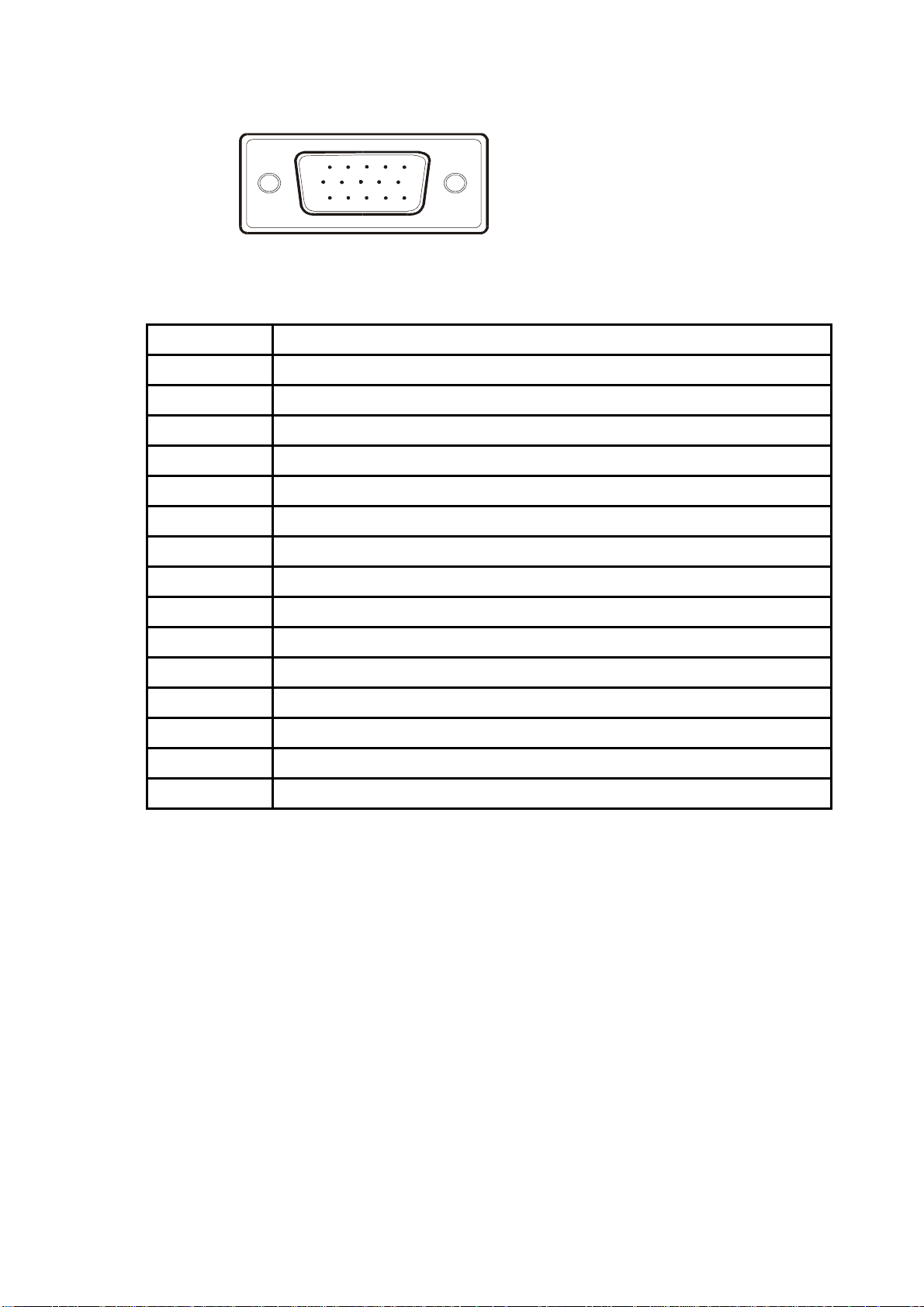
2.2 Interface description
15 pin D-sub connector pin assignment
1 5
6
11 15
10
Pin Number
1 Red video input
2 Green video input
3 Blue video input
4 No Connection
5 Ground
6 Red video ground
7 Green video ground
8 Blue video ground
9 +5V
10 H/V sync ground
11 No connection
12 (SDA)
13 Horizontal sync (Composite sync)
14 Vertical sync
Pin Function
15 (SCL)
Page 7
4
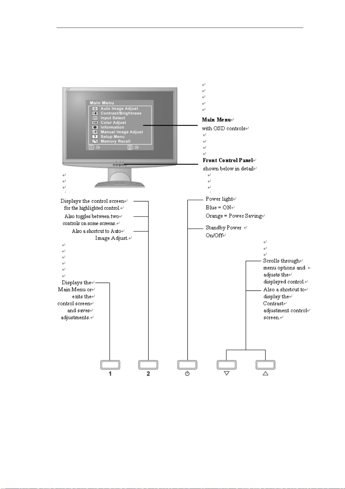
3. Front Panel Function Control Description
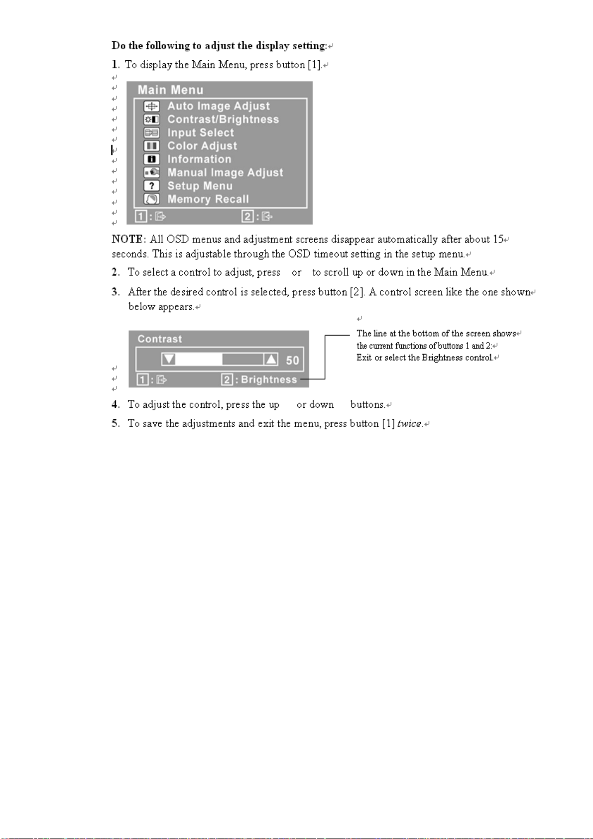
Use the buttons on the front control panel to display and adjust the OSD controls which
display on the screen. The OSD controls are explained at the top of the next page and
are defined in
“Main Menu Controls”
Page 8
5 6
Page 9
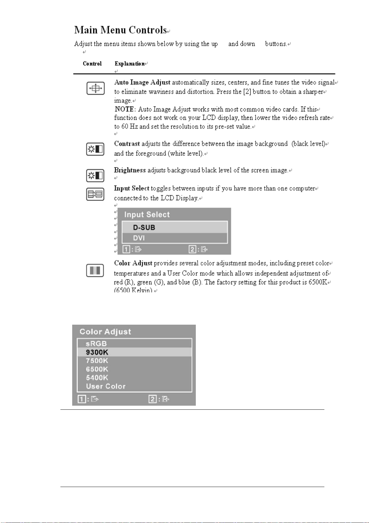
sRGB-This is quickly becoming the industry standard for color management,
with support being included in many of the latest applications. Enabling this
setting allows the LCD display to more accurately display colors the way they
were originally intended. Enabling the sRGB setting will cause the Contrast and
Brightness adjustments to be disabled.
9300K-Adds blue to the screen image for cooler white (used in most office
settings with fluorescent lighting).
Page 10
7
7500K - Adds blue to the screen image for cooler white (used in most office
settings with fluorescent lighting).
6500K-Adds red to the screen image for warmer white and richer red.
5400K-Adds green to the screen image for a darker color.
User Color Individual adjustments for red (R), green (G),and blue (B).
1. To select color (R, G or B) press button [2].
2. To adjust selected color, pressand.
Important: If you select RECALL from the Main Menu when the product is
set to a Preset Timing Mode, colors return to the 6500K factory
preset.
Information displays the timing mode (video signal input) coming from the
graphics card in the computer, the LCD model number, the serial number, and
the ViewSonic® website URL. See your graphics card’s user guide for
instructions on changing the resolution and refresh rate (vertical frequency).
NOTE: VESA 1680 x 1050 @ 60Hz (recommended) means that the resolution
is 1680 x 1050 and the refresh rate is 60 Hertz.
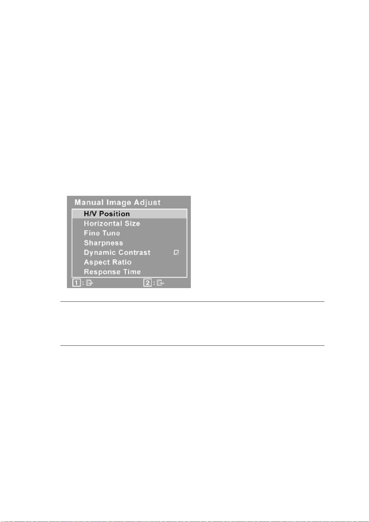
H./V. Position (Horizontal/Vertical Position) moves the screen
image left or
right and up or down.
H. Size (Horizontal Size) adjusts the width of the screen image.
Fine Tune sharpens the focus by aligning text and/or graphics
with pixel
boundaries.
NOTE: Try Auto Image Adjust first.
Sharpness adjusts the clarity and focus of the screen image.
Dynamic Contrast allows the user to turn the contrast ratio
enhancement on or
off.
Aspect ratio Selects the image size for 4:3 & full screen.
Response Time adjusts the response time of liquid-crystal display
for image
quality enhancement.
Page 11

8
Setup Menu displays the menu shown below:
Language Select allows the user to choose the language used in
the menus and
control screens.
Resolution Notice advises the optimal resolution to use.
OSD Position allows the user to move the OSD menus and
control screens.
OSD Timeout sets the length of time the OSD screen is displayed. For
example,
with a “15 second” setting, if a control is not pushed within 15
seconds, the
display screen disappears.
OSD Background allows the user to turn the OSD background
On or Off.
Memory Recall returns the adjustments back to factory settings
if the display is
operating in a factory Preset Timing Mode listed in the
Specifications of this
manual.
Exception: This control does not affect changes made with the
User Color control, Language Select or Power Lock setting.
Page 12
9
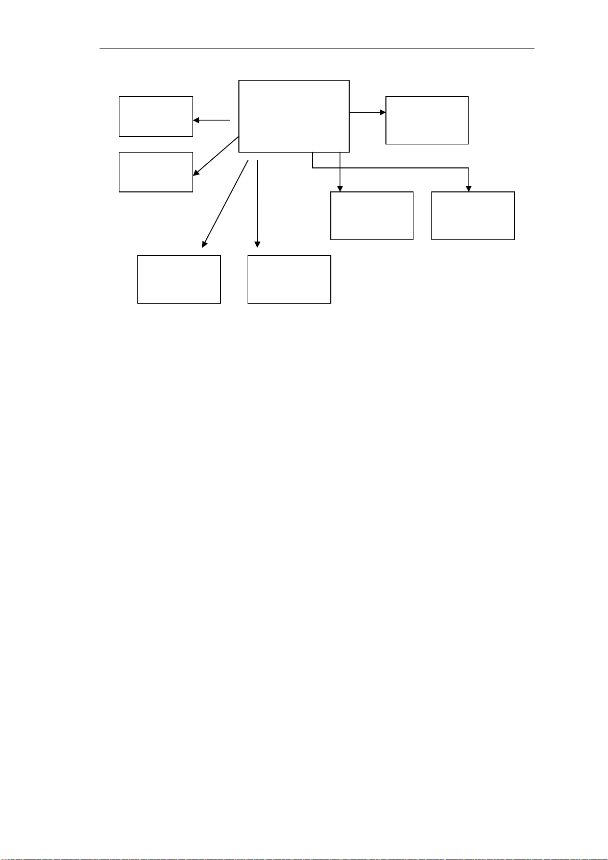
4. Circuit Description
EEprom
EEprom
Scaler
NT68670HTFG
EEprom
24C16
OSD control
D _SUB
LCD panel
DVI
board
The NT68670 is a highly integrated flat panel display controller that interfaces analog, digital,
and video inputs. It combines a triple ADC, a DVI compliant TMDS receiver, a digital YUV
receiver, a high quality zoom and shrink engine , a multi-color on screen display (OSD)
controller , an advanced color engine ,an liquid crystal display accelerator over – driving that
embedded 1Mx16 SDRAM and many other functions in a single chip. It provides the user with a
simple, flexible and cost-effective solution for various flat panel display products.
The NT68670 operates at frequencies up to 170MHz, suitable for LCD monitor up to UXGA
resolution.The NT68670 also has a built-in noise reduction function to provide more stable video
quality, spread spectrum to provide low EMI solution, sRGB for video color space convert and
post pattern for manufacture test.
The display provided multi-interface with timing controller or without timing controller. With
timing controller provided single/double pixel clock RSDS interface; without timing controller
provide single/double pixel clock LVDS interface.
In addition, NT68670 includes an integrated 8-Bit Microcontroller (MCU). It contains an
8-bit 8031 micro-controller, 1,280-bytes internal data memory, four 7-bit resolution A/D
Converter, 10-channel
8-bit resolution PWM DAC, two16-bit timer/counters, and a UART. Except those, it has
two-channel hardware DDC solution, and VESA 2Bi/2B+ master/slave I2C bus interface.
Page 13
10
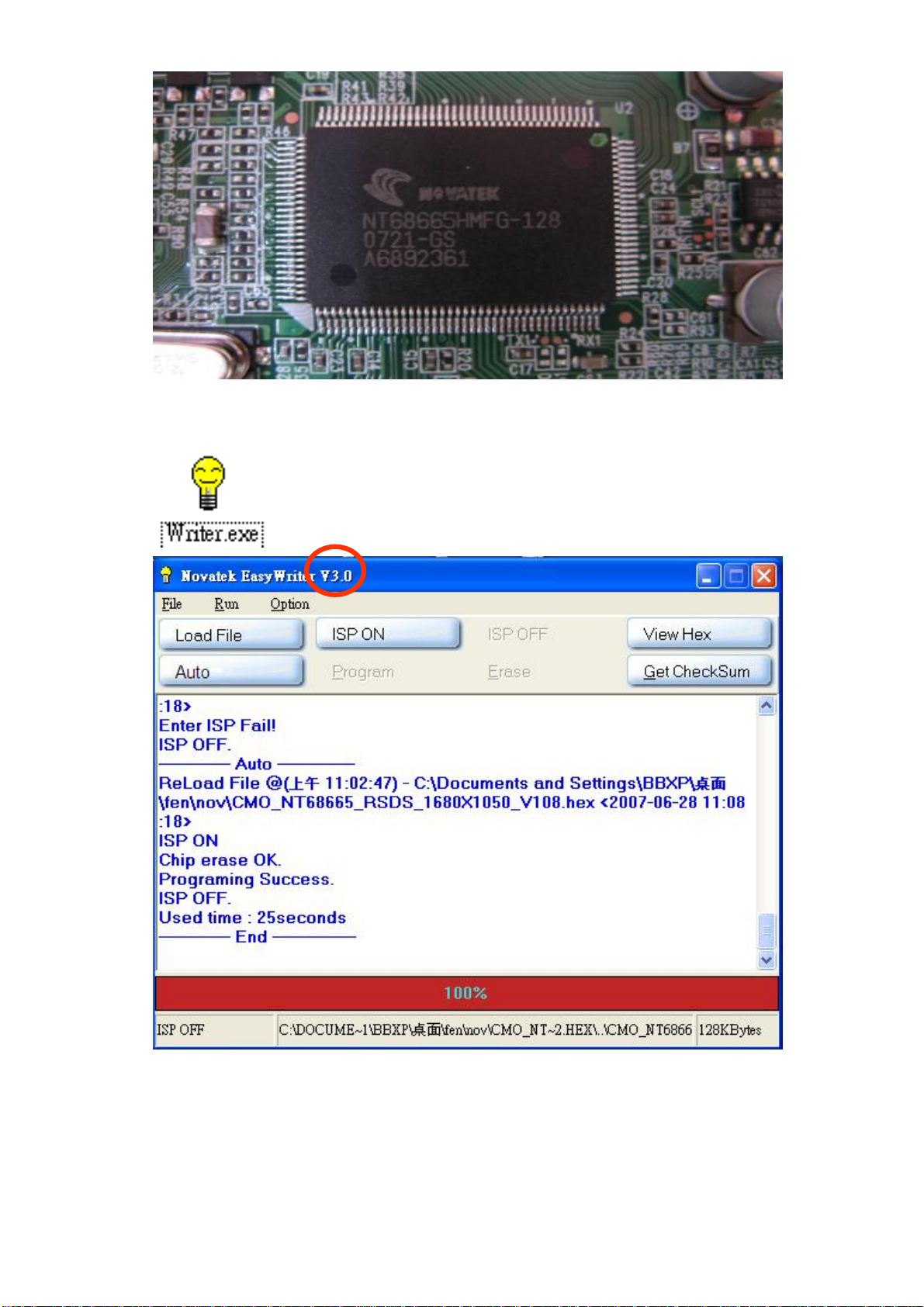
Writer Ver 3.0
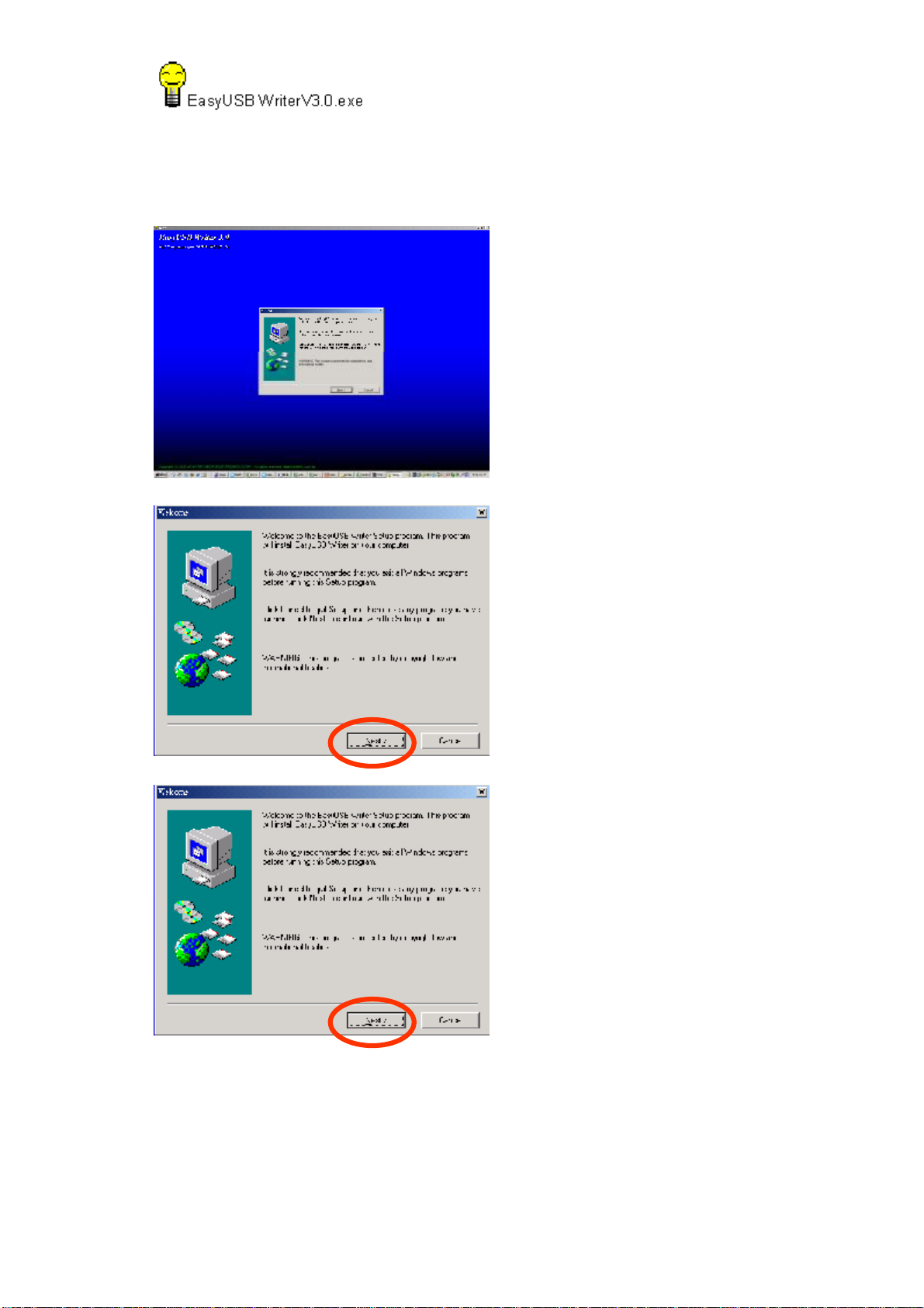
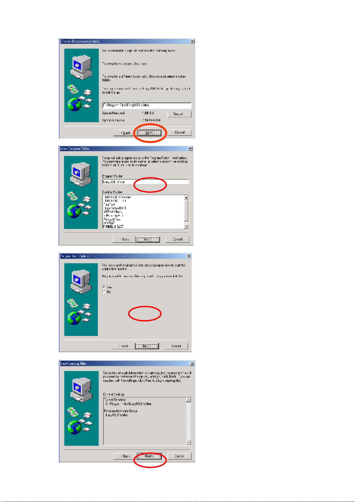
Setp1:
Setup EasyUSB WriterV3.0.exe
Page 14
11
Setp2:
Enter :
Page 15
12
Page 16
13
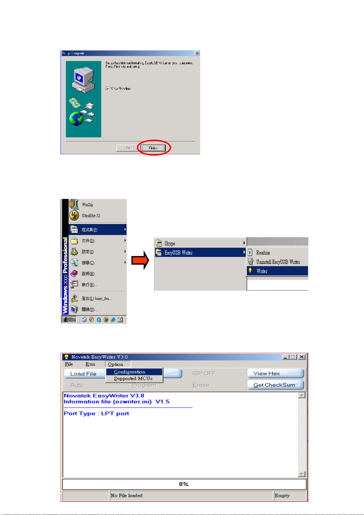
Step 3 :
Find Writer in this program.
Step 4 :
OptionàConfigurationàCHIMEIàConfirm change
Page 17

14
The IIC speed catches by
program.
Choose tools for CMO
Step 5 :
Print to D-Sub and DVI-D
Link Monitor which is update
Link PC
Step 6 :
BIOS update:
Load FileàAutoàFinish
Page 18

15
Page 19

16
5. Adjustment Procedure
1. All Modes Reset
You should do “All Model Reset” (Refer to Chap 3. Hot Keys for
Function Controls) first. This action will allow you to erase all
end-user’s settings and restore the factory defaults.
2. Auto Image Adjust
The Auto Adjust is aimed to offer a best screen quality by built-in
ASIC. For optimum screen quality, the user has to adjust each
function manually.
A.Turn the computer and LCD monitor on.
B. Press the ‘Auto’ button on monitor keypad to Auto Adjust.
C. The LCD monitor will start the Auto Adjust process automatically and
run for 10 consecutive seconds, during which time you will notice the
image change.
3. Firmware
Test Patten: Burn in Model (Refer to Chap3. Hot Keys for Function
Control)
-Make sure the F/W is the latest version.
4. DCC
Test Patten: EDID program
-Make sure it can pass test program.
5. Window Shut Down
Test Signal: 1280*1024@60Hz
Test Pattern:
Checkered Pattern Every One Pixel (50%Green & 50%Blue)
Inspection Item: Flicker, Mura
6. Window BG
Test Signal: 1280*1024@60Hz
Test Pattern:
Window standard pattern
Inspection Item: Line Defect, Function Defect & Mura
Page 20

17
7. 25 Gray
8. 50 Gray
Test Signal: 1280*1024@60Hz
Test Pattern:
Full Screen 25% White (Gray)
Inspection Item: Particle, Line Defect & Mura
Test Signal: 1280*1024@60Hz
Test Pattern:
Full Screen 50% White (Gray)
Inspection Item: Bright Dot, Particle, Line Defect & Mura
9. White Box
Test Signal: 1280*1024@60Hz
Test Pattern:
Window standard pattern
Inspection Item: Particle, Line Defect, Power, Image Remain & Mura
10. Black Box
Test Signal: 1280*1024@60Hz
Test Pattern:
Window standard pattern
Inspection Item: Bright Dot, Line Defect & Power
Page 21

18
11. RED
Test Signal: 1280*1024@60Hz
Test Pattern:
Full Screen Red
Inspection Item: Bright Dot, Partial & Line Defect
12. Green
Test Signal: 1280*1024@60Hz
Test Pattern:
Full Screen Green
Inspection Item: Bright Dot, Partial & Line Defect
13. Blue
Test Signal: 1280*1024@60Hz
Test Pattern:
Full Screen Green
Inspection Item: Bright Dot, Partial & Line Defect
14. Gray_Scale_0-100_V64
Test Signal: 1280*1024@60Hz
Test Pattern:
Vertical 64 (256) Gray Scale (Right → Left,From 0 to 100% White)
Inspection Item: Line Defect & Function Defect
Function Test Display pattern
Page 22

19
From 0 to
From
Item
1
2
3
4
5
6
7
8
Pattern Description Remark
Vertical 64 (256) Gray Scale (右→左,
Gray_Scale_0-100_V
100% White)
Horizontal 64 (256) Gray Scale (上→下,
Gray_Scale_0-100_H
0 to 100% White)
Black Full Screen Black Figure 3
Red Full Screen 50% Red Figure 4
Green Full Screen 50% Green Figure 5
Blue Full Screen 50% Blue Figure6
White Full Screen White Figure7
Black_Tile Black Tile Under White Background Figure 8
Figure 1
Figure 2
Figure 1
Figure 3 Figure 4
Figure 2
Page 23

20
Figure 5
Figure 6
Figure 7
Figure 8
Page 24

21
6. Troubleshooting
No power
• Make sure power button (or switch) is ON.
• Make sure A/C power cord is securely connected to the LCD display.
• Plug another electrical device (like a radio) into the power outlet to verify
that the outlet is
supplying proper voltage.
Power is ON but no screen image
• Make sure the video cable supplied with the LCD display is tightly secured to the
video
output port on the back of the computer. If the other end of the video cable is
not attached
permanently to the LCD display, tightly secure it to the LCD display.
• Adjust brightness and contrast.
• If you are using an Macintosh older than G3, you need a Macintosh adapter.
Wrong or abnormal colors
• If any colors (red, green, or blue) are missing, check the video cable to make
sure it is
securely connected. Loose or broken pins in the cable connector could cause an
improper
connection.
• Connect the LCD display to another computer.
• If you have an older graphics card, contact ViewSonic® for a non-DDC
adapter.
Control buttons do not work
• Press only one button at a time.
Page 25

22
7. Block Diagram
System
for HDCP
Power
Inveter
24C16
24C04
24C02
24C02
Audio
APA2068
MCU + Scaler
NT68665
KBoard
VGA
DVI
LVDS
Out
Page 26

23
8. Schematic Diagrams
Main board
TOP
+5V
ADC_VAA
ADC_VAA
B4
04_INTERFACE
ADC_VAA
INV_ADJ
DVDD
VGA_3V3
V33S
INV_ON/OFF
INV_ADJ
DVDD
VGA_3V3
V33S
V33S
DVDD
INV_ADJ
VGA_3V3
INV_ON/OFF
INV_ON/OFF
LED_ORG
LED_ORG
LED_ORG
LED_GRN
LED_GRN
LED_GRN
PWR_SW
PWR_SW
PWR_SW
MENU
MENU
MENU
KEY_UP
KEY_UP
KEY_UP
KEY_DOWN
KEY_DOWN
AUTO_ADJ
KEY_DOWN
AUTO_ADJ
AUTO_ADJ
SOURCE_SELECT
SOURCE_SELECT
SOURCE_SELECT
B5
MCU_VDD
MCU_VDD
MCU_VDD
LIPS_5V
SPK_R+
SPK_RSPK_L+
SPK_L-
CVDD1V8
CVDD1V8
CVDD1V8
LIPS_5V
SPK_R+
SPK_RSPK_L+
SPK_L-
05_AUDIO
MUTE
AMP_SHDN
VOL_PWM
MUTE
AMP_SHDN
VOL_PWM
MUTE
VOL_PWM
AMP_SHDN
OE
OE
VCM_PWM
VCM_PWM
GVON
GVON
GVON
VCM_PWM
LIPS_5V
SPK_R+
SPK_RSPK_L+
SPK_L-
PANEL_ON
PANEL_ON
PANEL_ON
+5V
STV
CKV
STB
POL
FSTHI
F_D[0..19]
B_D[0..19]
BSTHI
F_D[0..19]
B_D[0..19]
STB
POL
STVOECKV
FSTHI
BSTHI
POL
STV
STB
CKV
BSTHI
FSTHI
B_D[0..19]
F_D[0..19]
B1
+5V
02_VGA
SOGI
VGA_SDA
VGA_SCL
BI1
VGA_SDA
SOGI
VGA_SCL
B3
SOGI
VGA_SCL
VGA_SDA
ADC_VAA
RI1
RI1-
GI1-
BI1
BI1-
GI1
RI1
GI1
BI1-
BI1
GI1
RI1
HSIN
VSIN
RI1-
HSIN
VSIN
GI1-
BI1-
GI1-
RI1-
VSIN
HSIN
B6
+5V
ADC_VAA
03_SCALER
RX2-
RX2+
RX1-
RX1+
RX0-
RX0+
RXC-
RXC+
DVI_SCL
DVI_SDA
RX2-
RX2+
RX1-
RX1+
RX0-
RX0+
RXC-
RXC+
DVI_SCL
DVI_SDA
RX2-
RX1-
RX0-
RX2+
RX1+
RX0+
RXC-
RXC+
DVI_SCL
DVI_SDA
DVI_HPD
DVI_HPD
CVDD1V8
DVI_HPD
06_DVI
Page 27

24
VGA
GND_POWER
VGA_5V
1
2
3
U1
NC
VCC
NC
WP
NC
SCL
GND4SDA
AT24C02B-10TU-1.8/RoHS
VGA_SDA
VGA_SCL
+5V
1
2
D1
BAV70W/RoHS
3
8
VGA_5V
7
6
5
11
12
HSI
13
VSI
14
15
MLX89263-6762/RoHS
R2
0402/3.9K/5%
CN1
VGA_VDD
+5V 4,5
C3
0402/100n/16V/Y
GND_POWER
1
6
2
7
3
8
4
9
5
10
RAI+
GAI+
BAI+
VGA_SCL
VGA_SDA
VGA_SCL
VGA_SDA
RAIGAIBAI-
VSCL
1
TP
VSDA
1
TP
GND_POWER
RAI+
GAI+
1
GND_POWER
1
32
D2
NC/BAV99/RoHS
C4
NC/0402/100n/16V/Y
32
D3
NC/BAV99/RoHS
C7
NC/0402/100n/16V/Y
RAI-
B1
1 2
BK1608HS330
R3
0402/75R/1%
B2
1 2
BK1608HS330
R8
0402/75R/1%
100M/33ohm
R1 0402/56R/1%
R4 0402/100R/1%
R5 0402/470R/1%
R6 0402/56R/1%
R9 0402/100R/1%
C1 0402/47n/16V/Y
C2 0402/47n/16V/Y
C5 0402/47n/16V/Y
C6 0402/47n/16V/Y
RI1-
GI1
GI1-GAI-
RI1
RI1 3
RI1- 3
GI1 3
GI1- 3
CA1
0402/1n/16V/7
SOGI
R7
NC/0402/1M/1%
GND_POWER
SOGI 3
GND_POWER
VGA_5V
Z1
NC/UDZSF-5.6B/RoHS
1 2
GND_POWER
VSI
NC/UDZSF-5.6B/RoHS
Z3
1 2
GND_POWER
GND_POWER
1
GND_POWER
NC/UDZSF-1.9V
R15 0402/100R/5%
R14
0402/2.2K/5%
GND_POWER GND_POWER
32
D4
NC/BAV99/RoHS
C10
NC/0402/100n/16V/Y
GND_POWER
C12
0402/100p/50V/N
B3
1 2
BK1608HS330
R11
0402/75R/1%
ADC_VAA
R13 NC/0402/0R/5%
Z2
1 2
C11
NC/0603/10u/6.3V/5/B
GND_POWER
VSIN 3
HSI
NC/UDZSF-5.6B/RoHS
1 2
R10 0402/56R/1%
R12 0402/100R/1%
ADC_VAA3,4,5
Z4
GND_POWER
R17
0402/2.2K/5%
R16 0402/100R/5%
C13
0402/22p/50V/N
GND_POWER GND_POWER
C8 0402/47n/16V/Y
C9 0402/47n/16V/Y
HSIN 3
BI1BAI+
BI1 3
BI1-BAI-
BI1- 3
NC/UDZSF-5.6B/RoHS
VGA_VDD
R18
Z5
1 2
0402/4.7K/5%
VGA_SCL3
VGA_SDAVGA_SCL
NC/UDZSF-5.6B/RoHS
GND_POWERGND_POWER
VGA_VDD
R19
0402/4.7K/5%
VGA_SDA3
Z6
1 2
Page 28

25
scaler
DVDD
90
53
GND_POWER
115
52
GND_POWER
115
C19
0402/100n/16V/Y
CVDD1V8
C21
0402/100n/16V/Y
CVDD1V8
0402/0R/5%
R93
0402/100n/16V/Y
0402/100n/16V/Y
1206/10u/6.3V/5/RoHS
C18
C24
CVDD1V8
C22
GND_POWER
Pin51 to DVDD For NT68670 w/ 100nF
Pin51 to Pin33 For non-OD w/o 100nF
C61
0402/100n/16V/Y
GND_POWER
MCU_VDD
R30
R31NC/0402/10K/5%
NC/0402/10K/5%
TX
RX
SCL
SDA
For Debug Use
TX1
1
TP
RX1
1
TP
SCL1
1
TP
SDA1
1
TP
C14
0402/100n/16V/Y
DVDD
IRQn
0402/22p/50V/N
GND_POWER
VGA_3V3
15
C15
0402/100n/16V/Y
GND_POWER
VGA_3V3
RX2+5
RX2-5
RX1+5
RX1-5
RX0+5
RX0-5
RXC+5
RXC-5
HSIN2
VSIN2
BI12
BI1-2
SOGI2
GI12
GI1-2
RI12
RI1-2
VGA_SDA2
VGA_SCL2
DVI_SDA5
DVI_SCL5
AUTO_ADJ
SOURCE_SELECT
RSTN1
R34 0402/1M/5%
Y1
RSTn
1
TP
SDA
SCL
R33 0402/100R/5%
REFCLKI for NT68625/65
12 MHz
0402/22p/50V/N
GND_POWER
C26
C27
VGA_3V32,4,5
R20 0402/470R/1%
R22 0402/100R/5%
R24 0402/100R/5%
R25 0402/100R/5%
R26 0402/100R/5%
R28 NC/0402/100R/5%
MCU_VDD
C65
NC/0402/33p/50V/N
GND_POWER
GND_POWER
Option for NT68670
MCU_VDD
C23
0402/100n/16V/Y
GND_POWER
REFCLKI
TX
RX
R35
0402/100K/5%
C28
0402/100n/16V/Y
MCB1608S601EA
RX2+
RX2RX1+
RX1RX0+
RX0RXC+
RXC-
HSIN
VSIN
BI1
BI1-
SOGI
GI1
GI1-
RI1
RI1-
CVDD1V8
B14
0402/100n/16V/Y
U2
16
REXT
4
RX2+
5
RX2-
7
RX1+
8
RX1-
10
RX0+
11
RX0-
13
RXC+
14
RXC-
41
HSYNCI1
42
TOUTP/VSYNCI1
19
BIN1+
20
BIN1-
21
SOG1I
22
GIN1+
23
GIN1-
24
RIN1+
25
RIN1-
2
MCU_VCC
3
MCU_GND
34
PB7/DDC_SDA1
35
PB6/DDC_SCL1
46
PB5/DVI_SDA0
47
PB4/DVI_SCL0
30
PB3/ADC3/INTE1
33
PB2/ADC2/INTE0
125
PB1/ADC1
126
PB0/ADC0
48
RSTn/PD5
49
SDA/P35
50
SCL/P34
51
IRQn
44
TCLK
128
OSCO
127
OSCI
31
P31/TXD
32
P30/RXD
1
RSTB
NT68665
PWR_SW
MENU
KEY_UP
KEY_DOWN
AUDIO_FUNCTION
VGA_3V3
12
C20
DPLL
45
+
PLL_VDD
ADC_VAA
GND_POWER
C62
UWT1C221MCL1GS
43
52
115
CVDD
CVDD
PLL_GND
1 2
PVCCPVCC
6
15
17
26
AVCC
AVCC
PVCC
ADC_VAA
NT68625 for 19W DUSB only
NT68665 for 19W Dual
NT68665H for 22 wide Dual
NT68670TFG for 19 wide OD
NT68670HTFG for 22 wide OD
* => open drain(High Pulse)
** => initial low(initial low)
PD6
PD4
PD3
PD2
PD1
PD0
29
108
107
106
105
104
GND_POWER
Option for NT68670
NC(HSYNCI/GND)
119
109
CVDD1V8
NC(VSNCI/CVDD)
R91
0402/0R/5%
DVDDCVDD1V8
B4
0603/0R/RoHS
53
90
DVDD
DVDD
R92
0402/0R/5%
DVDD 2,4,5
9
12
18
27
101
78
AGND
AGND
PGND
ADC_GNDA
DGND/CGND
RSRA3M/T4M/G1/RSRB0M
RSRA3P/T4P/G0/RSRB0P
RSRA2M/T5M/B7/GSGB0M
RSRA2P/T5P/B6/RSGB0P
RSRA1M/T6M/B5/RSGB0M
RSRA1P/T6P/B4/RSBB0P
PA3/PWM536PA4/PWM6*37PA5/PWM7*38PA6/PWM8*39PA7/PWM9*
PA1/PWM367PA2/PWM466PA0/PWM2
65
0402/100n/16V/Y
GND_POWER
64
RSRB3M/DHS
RSRB3P/DVS
RSRB2M/DDE
RSRB2P/DCLK
RSRB1M/TTL_POL
DGND/CGND
DGND/CGND
RSGB3M/R7
RSGB3P/R6
RSGB2M/R5
RSGB2P/R4
RSGB1M/T0M/R3
RSGB1P/T0P/R2
RSBB3M/T2M/G7
RSBB3P/T2P/G6
RSBB2M/TCLK1M/G5
RSBB2P/TCLK1P/G4
RSBB1M/T3M/G3
RSBB1P/T3P/G2
RSCLKBM/T1M/R1
RSCLKBP/T1P/R0
RSGA3M/TCLK2M/B3
RSGA3P/TCLK2P/B2
RSGA2M/T7M/B1
RSGA2P/T7P/B0
RSGA1P/VCKI
RSCLKAM/V7
RSCLKAP/V6
RSBA3M/V5
RSBA3P/V4
RSBA2M/V3
RSBA2P/V2
RSBA1M/V1
RSBA1P/V0
GPO2/AD0
GPO3/AD1
INT_VSO/GPO4
INT_HSO/GPO5
*PWMA/GPO7
*PWMB/GPO8
PC3/PWM0
PC4/PWM1
40
LED_ORG
VCM_PWM
LED_GRN
PVCC
176
C16
RSRB1P
RSGA1M
SP
GPO1
GPO6
**PC0
**PC1
PC2
PC5
PC6
PC7
24C04_SDA
24C04_SCL
24C04_WP
0402/100n/16V/Y
GND_POWER
100
99
98
97
96
95
94
93
92
91
88
87
84
83
82
81
80
79
86
85
77
76
75
74
73
72
71
70
69
68
63
62
61
60
59
58
57
56
55
54
89
110
111
112
113
114
116
117
118
120
121
28
122
123
124
102
103
DVI_HPD5
LED_ORG4
VCM_PWM4
LED_GRN4
ADC_VAA
26
B_D17
B_D16
B_D15
B_D14
B_D13
B_D12
B_D11
B_D10
B_D9
B_D8
B_D7
B_D6
B_D5
B_D4
B_D3
B_D2
B_D1
B_D0
B_D19
B_D18
F_D17
F_D16
F_D15
F_D14
F_D13
F_D12
F_D11
F_D10
F_D9
F_D8
F_D7
F_D6
F_D19
F_D18
F_D5
F_D4
F_D3
F_D2
F_D1
F_D0
C17
B_D[0..19]
F_D[0..19]
R29
ADC_VAA2,4,5
C63
0603/10u/6.3V/5/B
GND_POWER
R27
0402/10K/5%
0402/10K/5%
B_D[0..19]4
F_D[0..19]4
V33S
MUTE
MUTE
VOL_ADJ
HSO
WP
FSTHI
V33S
R36
R90
0402/4.7K/5%
0402/10K/5%
0402/10K/5%
R38 0402/4.7K/5%
R96 0402/1K/5%
C66
0402/1u/6.3V/5
GND_POWER
R37
BSTHIBSTHIBSTHIBSTHI
FSTHIFSTHIFSTHIFSTHI
OEOEOEOEOE
POLPOLPOLPOLPOLPOLPOLPOLPOLPOLPOLPOLPOLPOLPOLPOLPOLPOLPOLPOLPOLPOLPOLPOLPOLPOLPOLPOLPOLPOLPOLPOLPOLPOLPOL
STV
GVON
HSO
CKV
STB
R40
NC/0402/10K/5%
GND_POWER
GND_POWER
BSTHI 4
FSTHI 4
OE 4
POL 4
STV 4
GVON 4
CKV 4
STB 4
INV_ON/OFF4
PANEL_ON4
MUTE 6
U3
1
A0
2
A1
3
A2
4
SEEPROM
GND
24LC16BT-I/SNG/RoHS
V33S
R32
0402/4.7K/5%
V33S
R39
0402/10K/5%
R41
NC/0402/10K/5%
GND_POWER
MCU_VDD
R21
8
VCC
7
TEST
6
SCL
5
SDA
C25
0402/100n/16V/Y
GND_POWER
INV_ADJ 4
Pin123 High-->Dual
Pin123 Low-->Analog only
MCU_VDD2,4,5
R23
0402/3.3K/5%
0402/3.3K/5%
WPWPWPWPWPWPWPWPWPWPWPWPWPWPWPWPWPWPWPWP
SCL
SDASDA
8
7
6
5
0402/100n/16V/Y
GND_POWER
MCU_VDD
R51
R53 0402/3.3K/5%
R50
24C04_WP
C30
24C04_SCL
24C04_SDA
0402/3.3K/5%
0402/3.3K/5%
24C04_WP
24C04_SCL
24C04_SDA
1
TP
1
TP
1
TP
MUTE
HWP
HSCL
HSDA
MCU_VDD
R42
0402/10K/5%
0402/10K/5%
0402/10K/5%
0402/10K/5%
0402/10K/5%
0402/10K/5%
SOURCE_SELECT4
AUTO_ADJ4
KEY_DOWN4
KEY_UP4
MENU4
PWR_SW4
SOURCE_SELECT
AUTO_ADJ
KEY_DOWN
KEY_UP
MENU
PWR_SWPWR_SW
R46
R43
R47
R44
R45
High w/o Audio
Low with Audio
AUDIO_FUNCTION
V33S
GND_POWER
R52
NC/0402/10K/5%
R55
0402/10K/5%
VOL_ADJ
V33S
R48
0402/1K/5%
R49 0402/10K/5%
V33S 2,4,5
C29
0805/1u/25V/7
GND_POWER
VOL_PWM6
GND_POWER
HDCP
OPTION
U4
1
A0
2
A1
3
A2
4
SEEPROM
GND
AT24C04N-10S1-2.7/RoHS
VCC
TEST
SCL
SDA
R54
0402/10K/5%
Q1
1
GND_POWER
V33S
AMP_SHDN6
32
2N7002/RoHS
Page 29

26
interface
HEADER2X4FR2.54/RoHS
8
7
6
5
4
3
2
1
CN2
B8 0603/0R/RoHS12
B9 0603/0R/RoHS12
B10 0603/0R/RoHS12
[INV_GND]
INV_ADJ 3
INV_ON/OFF3
GND_POWER
LIPS Interface
LIPS_5V
LIPS_5V6
B5 0805/0R/5%1 2
0402/100n/16V/Y
C31
+5V
GND_POWER
+5V
1
TP
C33
1206/10u/10V/Y/E
+5V1
+5V 2,5
VGA_3V3
+5V
D5
1 2
EC31QS03L/RoHS
1 2
0805/0R/5%
B6
EC50117KAG/3.3V/1A
U5
3
VOUT
VIN
VOUT
GND
1
C32
1206/10u/10V/Y/E
1206/10u/6.3V/5/RoHS
2
4
C34
0805/0R/5%
+
C64
LV101M016E055R
1 2
V33S
B7
V33S 2,3,5
DVDD
ADC_VAA
MCU_VDD
VGA_3V32,3,5
DVDD 2,3,5
ADC_VAA2,3,5
MCU_VDD2,3,5
(SCALER VCC)
V33S
C57
1206/10u/10V/Y
3
C58
0402/100n/16V/Y
GND_POWER
U8
L1117LG-1.8
VOUT
VIN
VOUT
GND
1
2
4
1206/10u/6.3V/5
C59
V18C1
TP
1
Option for NT68670
C60
0402/100n/16V/Y
Scaler Core
B13
Bead/220R/2A/0603/RoHS
12
CVDD1V8
GND
OSD Interface
SOURCE_SELECT3
AUTO_ADJ3
KEY_DOWN3
KEY_UP3
MENU3
PWR_SW3
SPK_R-6
SPK_R+6
SPK_L-6
SPK_L+6
LED_ORG3
R56 0402/33R/5%
R63 0402/33R/5%
R57 0402/33R/5%
R58 0402/33R/5%
R59 0402/33R/5%
LED_O
R60 0402/33R/5%
LED_G
R62 0402/33R/5%
R61 0402/33R/5%
L1 MPZ1608S221ATA00/RoHS
L2 MPZ1608S221ATA00/RoHS
L4 MPZ1608S221ATA00/RoHS
L3 MPZ1608S221ATA00/RoHS
C35
R64
0402/10K/5%
R66 0402/4.7K/5%
C39
C40
C36
C37
NC/0402/100n/16V/Y
NC/0402/100n/16V/Y
NC/0402/100n/16V/Y
NC/0402/100n/16V/Y
NC/0402/100n/16V/Y
NC/0402/100n/16V/Y
V33S
23
Q2
1
SST3906F
V33S
C38
R65
0402/240R/1%
LED_O
GND_POWER
GND_POWER
CN4
15
14
13
12
11
10
9
8
7
6
5
4
3
2
1
7101N-E015-NNN/RoHS
+5V
R67
0402/33K/5%
B_D[0..19]3
F_D[0..19]3
AP2305GN
1
VCM_PWM3
Q3
32
0402/10M/5%
X Board Interface
BB2PB_D17
BB2NB_D16
BB1PB_D15
BB1NB_D14
BB0PB_D13
BB0NB_D12
BG2PB_D11
BG2NB_D10
BG1PB_D9
BG1NB_D8
BG0PB_D7
BG0NB_D6
BCKPB_D19
BCKNB_D18
BR2PB_D5
BR2NB_D4
BR1PB_D3
BR1NB_D2
BR0PB_D1
BR0NB_D0
FB2PF_D17
FB2NF_D16
FB1PF_D15
FB1NF_D14
FB0PF_D13
FB0NF_D12
FG2PF_D11
FG2NF_D10
FG1PF_D9
FG1NF_D8
FG0PF_D7
FG0NF_D6
FCKPF_D19
FCKNF_D18
FR2PF_D5
FR2NF_D4
FR1PF_D3
FR1NF_D2
FR0PF_D1
FR0NF_D0
BSTHI
FSTHI
POL
STB
STV
CKV
OE
GVON
VCM_PWM
C41
1206/10u/10V/Y/E
R68
BSTHI3
FSTHI3
POL3
STB3
STV3
CKV3
OE3
GVON3
V5P
CN3
55
55
54
54
53
53
52
52
51
51
50
50
49
49
48
48
47
47
46
46
45
45
44
44
43
43
42
42
41
41
40
40
39
39
38
38
37
37
36
36
35
35
34
34
33
33
32
32
31
31
30
30
29
29
28
28
27
27
26
26
25
25
24
24
23
23
22
22
21
21
20
20
19
19
18
18
17
17
16
16
15
15
14
14
13
13
12
12
11
11
10
10
9
9
8
8
7
7
6
6
5
5
4
4
3
3
2
2
1
1
089H55-000000-G2
R69
R70
0402/10K/5%
LED_GRN3
R72 0402/4.7K/5%
SST3906F
R71
0402/240R/1%
Q4
23
Q5
1
LED_G
PANEL_ON3
PANEL_ON
32
1
2N7002/RoHS
GND_POWER
0402/1K/5%
GND_POWER
Page 30

27
DVI
DVI_SCL
DVI_SDA
DVI_5V
U6
1
NC
2
3
CN5
SYNC GND
2DS-0342-S01/RoHS
VCC
NC
VCLK
NC
SCL
GND4SDA
AT24C02B-10TU-1.8/RoHS
25
R
26
G
27
B
HSYNC
VSYNC
+5V
HPD
DAT0+
DAT0-
DAT1+
DAT1-
DAT2+
DAT2-
DAT3+
DAT3-
DAT4+
DAT4-
DAT5+
DAT5-
clk+
clk-
DVI_5V
29
28
8
15
6
7
14
16
11
3
19
22
18
17
10
9
2
1
13
12
5
4
21
20
23
24
RGB GND
DDC SCL
DDC SDA
1/3shield
2/4shield
0/5shield
clk shield
R73 0402/100R/5%
R75 0402/100R/5%
+5V
1
2
D6
BAV70W/RoHS
3
8
7
6
5
GND_POWER
+5V2,4
R78 0402/3.9K/5%
DVI_5V
DVI_SCL
DVI_SDA
DATA0+
DATA0DATA1+
DATA1DATA2+
DATA2-
CLK+
CLK-
DVI_VDD
0402/47K/5%
CVDD1V8
R82
0402/1K/5%
For 686x5 series DVI Read EDID Fail
CVDD1V8
R95
NC/0402/2.2K/5%
R80
R81 0402/10K/5%
DVI_HPD 3
C42
R79
R77
NC/0402/10K/5%
NC/0402/10K/5%
0402/100n/16V/Y
GND_POWERGND_POWER
DATA0+DATA0+
DATA1+ RX1+ DATA1- RX1-
DATA2+DATA2+DATA2+
CLK+ RXC-RXC-
DVI_SCL
1
DVI_SDA
1
32
NC/0402/100n/16V/Y
32
NC/0402/100n/16V/Y
32
NC/0402/100n/16V/Y
32
DSCL
TP
DSDA
TP
D7
NC/BAV99/RoHS
1
C43
D9
NC/BAV99/RoHS
1
C45
D11
NC/BAV99/RoHS
1
C47
D13
NC/BAV99/RoHS
1
0402/4.7K/5%
DVI_SCL
DVI_VDD
R74
1 2
GND_POWER
DVI_VDD
R76
0402/4.7K/5%
DVI_SCL 3
Z7
NC/UDZSF-5.6B/RoHS
RX0+RX0+ RX0-
RX2+RX2+
RXC+
DVI_SDA
Z8
NC/UDZSF-5.6B/RoHS
1 2
GND_POWER
RX0+ 3
RX1+ 3 RX1- 3
RXC+ 3
DATA0-
DATA2- RX2-
CLK-CLK-CLK-
DVI_SDA 3
D8
32
NC/BAV99/RoHS
1
C44
NC/0402/100n/16V/Y
D10
32
NC/BAV99/RoHS
1
C46
NC/0402/100n/16V/Y
D12
32
NC/BAV99/RoHS
1
C48
NC/0402/100n/16V/Y
D14
32
NC/BAV99/RoHS
1
RX0- 3
RX2- 3RX2+ 3
RXC- 3
Z9
1 2
NC/UDZSF-5.6B/RoHS
GND_POWER
C49
NC/0402/100n/16V/Y
GND_POWER
ADC_VAA
ADC_VAA2,3,4
Z10
NC/UDZSF-3.6B/RoHS
GND_POWER
C50
NC/0402/100n/16V/Y
Page 31

28
Audio
J1
2SJ-05101NC3
1
3
11
10
2
GND
D15 NC/VPORT0603470KV05T
GND_AUDIO
GND_AUDIO
GND_AUDIO
R84 0402/0R/5%
RIN
1 2
R85 0402/0R/5%
LIN
12
D16
NC/VPORT0603470KV05T
GND
LIPS_5V4
C54 0402/1u/10V/Y
RIN-
C56 0402/1u/10V/Y
LIN-
R86 NC/0402/0R/5%
RIN
R87 NC/0402/0R/5%
LIN
LIPS_5V
LV101M016E055R
C51
LIN-
RIN-
5V_AMP
R83 0603/0R/5%
+
GND
C52
1206/10u/10V/Y
GND
C53
1206/10u/10V/Y
U7
VDD
GND
VDD
16
15
14
13
GND
12
11
10
9
MUTE3 SPK_R- 4
AMP_SHDN3
C55 0805/2.2u/16V/Y
GND
GND GND
VOL_PWM3
1
MUTE
2
/SHDN
3
RIN-
4
BYPASS
5
GND
6
LIN-
7
VOL
VOLMAX8LOUT-
ROUT-
ROUT+
SE/BTL
LOUT+
APA2068
R88 NC/0402/0R/5%
5V_AMP
R89 0402/0R/5%
GND
5V_AMP
SPK_R+ 4
SPK_L+ 4
5V_AMP
SPK_L- 4
Power Board
GND_AUDIO
GND GND_POWER
Page 32

7654321
DELTA DOC CENTER
29
8
R116
C104
R117
D
D110
3
3
1
2
D
F100
CN100
1
2
3
C
B
CY100
CY101
R107
R108
CE
R100
3
1
LF100
VCC
R101
A K
ZD103
C110
CX100
2
4
1
2
3
4
R102
VAR100
EC
B
Q102
R109
B
Q103
R115
D109
CX101
U100
D101
D103
D100
R103
NTC100
D102
8
7
6
5
+
CE100
R105
R110
R111
R112
R129
C101
R104
C102
R138
R139
D105
R113
R106
1
2
Q100
2
1
R114
C100
D104
VCC
C100_1
L100
D106
R120
+
CE101
ZD102
R131
T101
1 10
3
4
5
U101
C103
5V19V
A K
A K
9
8
7
6
GND
ZD101
C109
B
A K
A K
3
1
R118
R119
CY102
CE
GND
3
Q101
D108
D107
C105
U102
2
D112
R122
GND
GND
R121
R123
+
+
C107
CE102
CE105
C106
L102
L101
CE106
+
+
CE104
R135
R136
R137
A K
R130
R124
R125
R126
ZD100
R127
R128
ZD104
5V
C111
A K
R132
B
R133
5V
F101
C108
GND
ON/OFF
ADJ
DAC-19M020 AF-INV-R0C3X03.SCH
DAC-19M020 AF-INV-R0C3X03.SCH
19V
R134
CE
Q104
GND
C
CN5
1
2
3
4
5
6
7
8
B
A
THESE DRAWINGS AND SPECIFICATIONS ARE THE PROPERTY OF DELTA ELECTRONICS, INC.
AND SHALL NOT BE REPRODUCED OR USED AS THE BASIS FOR THE MANUFACTURE OR
SELL OF APPARATUSES OR DEVICES WITHOUT PERMISSION.
Frame Name:FR9-1R00.DOT
DELTA ELECTRONICS, INC.
1 2 3 4 5 6 78
DAC-19M020 AF
PCB:
DESCRIPTION:
SCHEMATIC OF TELECOM POWER
LY.REV:Date:
DAC-19M020 AF-ADP-R0C3X03.SCH
FILE NAME:
Drawn:
GND
GND
A
CHIAO06/25'07
Checked Approved PART NO:
呂昭賢
李文中
REV.
SHEET
OF
210
Page 33

DELTA DOC CENTER
7654321
DELTA DOC CENTER
30
CN200
1
R244
C239
K
R245
C240
K
R246
C241
K
R247
C242
K
2
D209
D211
D213
K
D215
R213
R214
K
R215
R216
K
R217
R218
K
R219
R220
A
CN201
1
2
A
CN202
1
2
A
CN203
1
2
A
R
R
R
R
R211
VIN
R212
D201
DS
Q205
G
C209
(00A-7037 A,漏感220mH)
2 4
R248
C205
7
3 8
6
R253
DS
C206
Q208
R229
C226
R230
C227
R231
C228
R232
C229
C214
D208
R
C210
C235
C234
C216-1
C211
C213
C215-1
C212
NC
C219
C237
C218
A
C215
D210
R
C236
A
C216
D212
R
A
C217
D214
R
A
T200
5
1
OP1
OP2
OP3
OP4
C204
G
D203
D204
D205
R222
D200
C224
R200
F200
R201
R224
R202
5V
R204
R233
D216
R255
Q200
B
CE
Q201
B
R203
16
OPOUT
INN1CMP2LOAD3CTOSC4TIMER5SST6GND7OUT1
C225
R225
C E
ZD200
SEN1
15
14
OPIN
SEN213SEN1
R226
C230
C233
S1
R242
S1
JP201
R241
R250
R243
R234
12
C202
S3
ONOFF
C221
IC_VCC
JP202
R228
R256
R257
11
S4
MODE
C201
R236
9
10
IC200
VDD
OUT2
8
C238
C223
IC_VCC
R237
D202
R223
+19V
ON/OFF
ADJ
D
C220
R221
C
C222
B
8
OP1
R207
OP2
R208
OP3
R209
OP4
R210
D
C
B
A
DELTA ELECTRONICS, INC.
THESE DRAWINGS AND SPECIFICATIONS ARE THE PROPERTY OF DELTA ELECTRONICS, INC.
THESE DRAWINGS AND SPECIFICATIONS ARE THE PROPERTY OF DELTA ELECTRONICS, INC.
AND SHALL NOT BE REPRODUCED OR USED AS THE BASIS FOR THE MANUFACTURE OR
AND SHALL NOT BE REPRODUCED OR USED AS THE BASIS FOR THE MANUFACTURE OR
SELL OF APPARATUSES OR DEVICES WITHOUT PERMISSION.
SELL OF APPARATUSES OR DEVICES WITHOUT PERMISSION.
Frame Name:FR9-1R00.DOT
Frame Name:FR9-1R00.DOT
DELTA ELECTRONICS, INC.
1 2 3 4 5 6 78
C231
R227
SEN1
DS
Q203
G
R238
05/22'07
PCB:
PCB:
DESCRIPTION:
DESCRIPTION:
SCHEMATIC OF TELECOM POWER
SCHEMATIC OF TELECOM POWER
ZD202
C232
LY.REV:Date:
LY.REV:Date:
FILE NAME:
FILE NAME:
D206
1
3
R240
D207
3
R239
CHIAO
Drawn:
DAC-19M020 AF-INV-R0C3X03.SCHDAC-19M020 AF
Drawn:
OP1
2
OP2
1
OP3
2
OP4
Checked Approved PART NO:
Checked Approved PART NO:
蔡志弘
李文中
REV.
REV.
SHEET
SHEET
OF
OF
A
220
Page 34

31
9. PCB Layout Diagrams
Page 35

Page 36

33
10. Exploded Diagram and Exploded Parts List
Page 37

34
Page 38

33
TC6MNBHKNWVSN
ViewSonic Model Number:VX2240W-4
Rev:
ViewSonic
Item
1 750GLMC0KZ512C000Q PANEL A220Z5 VSC CMO/SM0Z131D01 1
2 0M1G 330 4120 SCREW 42A9930008 4
3 N52G 1VSC010 HB
4 N52G 1211001 HB
5 089G176C 55N04 FFC Cable 55P 155MM/32-D019364 1
6 N52G 1VSC011 ISOLATED TAPE 73-D018291 1
7 0M1G1740 8120
8 002G6008 2 SCREW 42-D015647 4
9 017G MBN1IUSIC000 MB 35-D019445/10-D024286/001071227_2 1
P/N Ref. P/N Description Q'ty
Conductive Tape 277mm *15mm *0.06mm (单
导) 2
Conductive Tape 155mm *15mm *0.06mm(单
导) 2
SCREW FOR STD/MF
42-D020715/42-D000649 1
10 089G176C 15N17 FFC CABLE 15P 248.7mm/32-D021932 1
11 80GL22708DE POWER BOARD/27-D018867 1
12 N85G0011 1 WQ COVER AD 41-D022926 1
13 705GN734132 ZY BEZEL ASSY 40-D021924 1
14 705GN734133 ZY REAR ASSY 40-D021927 1
15 705GN734134 ZY STAND ASS'Y 40-D021930 1
16 705GN734130 ZY COVER HINGE ASS'Y40-D021919 1
17 0M1G1740 10120 SCREW 42A9940008 4
18 0Q1G 330 5120 SCREW 42-D003574 2
19 705GN734131 ZY SEAT ASS'Y 40-D021922 1
Page 39

34
11. Recommended Spare Parts List
TC6MNBDTNWVWN
Location Part No. Description Remark
705GN734132 ZY BEZEL ASSY 40-D021924
N44GC010968 1B CARTON- 78-D023666
N40G000196855A CARTON LABEL
EDIDVSC22D001 CHECKSUM 0X09
EDIDVSC22A001 CHECKSUM 0XB4
N52G 1VSC006 HB Conductive Tape 60mm *24mm *0.06mm main source
N52G 1211001 Conductive Tape 155mm *15mm *0.06mm
N52G 1211001 HB Conductive Tape 155mm *15mm *0.06mm main source
N52G 1VSC010 HB Conductive Tape 277mm *15mm *0.06mm main source
N52G 1VSC010 Conductive Tape 277mm *15mm *0.06mm
N52G 1VSC006 Conductive Tape 60mm *24mm *0.06mm
N44G9003185 CORNER PAPER 7841595111/78-D004862
N44G9003 80 CORNER PAPER 78-D004868
N85G0011 1 WQ COVER AD 41-D022926
705GN734130 ZY COVER HINGE ASS'Y40-D021919
N44GC010 1 MZ CUSHION LEFT 78-D022378
N44GC010 2 MZ CUSHION RIGHT 78-D022387
089G 728HAA DB D-SUB CABLE
089G1738SAA600 D-SUB CABLE 1800mm 32-D002132
089G1738JAA 23 D-SUB CABLE 1800mm 32F3018003
089G 728CAAN00 D-SUB CANBLE 1800MM 32-D002132 main source
089G1748HAA AC DVI CABLE
089G1748JAA600 DVI Cable 1800mm / 32F0000004
089G1748SAAA01 DVI CORD 32-D013540
089G176C 15N17 FFC CABLE 15P 248.7mm/32-D021932
089G176C 55N04 FFC Cable 55P 155MM/32-D019364 main source
089G176J 55N01 FFC CABLE 55P 155MM/32-D019364
N52G 1VSC011 ISOLATED TAPE 73-D018291
KEPC7NC3 KEY BOARD/35-D023591
N41G220296832A MANUAL 76-D022380
017G MBN1IUSIC000 MB 35-D019445/10-D024286/001071227_2
N07G0006 1 HW PALLET- 78-D020542
750GLMC0KZ512C000Q PANEL A220Z5 VSC CMO/SM0Z131D01
N52G6020001 HB panel protector film
N45G 88607004 HQ PE BAG FOR SKD 78-D019961
N45G 52001 PE SHEET
N40G000296824A POP LABEL- 77-D022273
Page 40

35
80GL22708DE POWER BOARD/27-D018867 main source
80GL22700YY POWER BOARD/27-D018868
089G412A18NISC POWER CORD 32E1818058
POWER CORD
089G415A18NISC
089G404A18N YH POWER CORD(32E1818018/32-D022217) main source
089G421A18N IS POWER CORD/32-D022217
089G412A18NIS3 POWER CORD/32E1818058 main source
705GN734133 ZY REAR ASSY 40-D021927
N40G0001968 2A S/N LABEL 7741513161
N40G000196831A S/N LABEL- 77-D022381
N40G 22N96821C SAFETY LABEL
002G6008 2 SCREW 42-D015647
0M1G 330 4120 SCREW 42A9930008
0M1G1740 10120 SCREW 42A9940008
0Q1G 330 5120 SCREW 42-D003574
0M1G1740 8120
705GN734131 ZY SEAT ASS'Y 40-D021922
N52G 1VSC002 HY Security Tape- 7345511002
I-SHENG(KR&EU)/32-D022217
SCREW FOR STD/MF
42-D020715/42-D000649
N44GC010VSC 1A Shipping Draw- 79-D022372
089G1748CAA AC SIGNAL CABLE DVI COMLINK main source
705GN734134 ZY STAND ASS'Y 40-D021930
N52G 2191 01 TAPE /7345911004
050G 600 1 W WHITE STRAP
095G8014 2N00 WIRE HARNESS 2P-2P 20MM/32-D016783
095G8014 2N01 WIRE HARNESS 2P-2P 40MM/32-D015712
P45G 77001 enlace film
TC6MNBDTNWVWNND
Location Part No. Description Remark
705GN734132 ZY BEZEL ASSY 40-D021924
N44GC010968 1B CARTON- 78-D023666
N40G000196855A CARTON LABEL
EDIDVSC22D001 CHECKSUM 0X09
EDIDVSC22A001 CHECKSUM 0XB4
N52G 1VSC006 HB Conductive Tape 60mm *24mm *0.06mm main source
N52G 1211001 Conductive Tape 155mm *15mm *0.06mm
N52G 1211001 HB Conductive Tape 155mm *15mm *0.06mm main source
N52G 1VSC010 HB Conductive Tape 277mm *15mm *0.06mm main source
N52G 1VSC010 Conductive Tape 277mm *15mm *0.06mm
Page 41

36
N52G 1VSC006 Conductive Tape 60mm *24mm *0.06mm
N44G9003185 CORNER PAPER 7841595111/78-D004862
N44G9003 80 CORNER PAPER 78-D004868
N85G0011 1 WQ COVER AD 41-D022926
705GN734130 ZY COVER HINGE ASS'Y40-D021919
N44GC010 1 MZ CUSHION LEFT 78-D022378
N44GC010 2 MZ CUSHION RIGHT 78-D022387
089G1738SAA600 D-SUB CABLE 1800mm 32-D002132
089G1738JAA 23 D-SUB CABLE 1800mm 32F3018003
089G 728CAAN00 D-SUB CANBLE 1800MM 32-D002132 main source
089G1748HAA AC DVI CABLE main source
089G1748JAA600 DVI Cable 1800mm / 32F0000004
089G1748SAAA01 DVI CORD 32-D013540
089G176C 15N17 FFC CABLE 15P 248.7mm/32-D021932
089G176C 55N04 FFC Cable 55P 155MM/32-D019364
N52G 1VSC011 ISOLATED TAPE 73-D018291
KEPC7NC1 KEY BOARD/35-D021770
KEPC7NC3 KEY BOARD/35-D023591 main source
N41G220296832A MANUAL 76-D022380
017G MBN1IUSIC000 MB 35-D019445/10-D024286/001071227_2
N07G0006 1 HW PALLET- 78-D020542
750GLMC0KZ512C000Q PANEL A220Z5 VSC CMO/SM0Z131D01
N52G6020001 HB panel protector film
N45G 88607004 HQ PE BAG FOR SKD 78-D019961
N45G 52001 PE SHEET
N40G000296824A POP LABEL- 77-D022273
80GL22708DE POWER BOARD/27-D018867 main source
80GL22700YY POWER BOARD/27-D018868
089G412A18NISC POWER CORD 32E1818058
POWER CORD
089G415A18NISC
089G404A18N YH POWER CORD(32E1818018/32-D022217) main source
I-SHENG(KR&EU)/32-D022217
089G421A18N IS POWER CORD/32-D022217
089G412A18NIS3 POWER CORD/32E1818058 main source
705GN734133 ZY REAR ASSY 40-D021927
N40G0001968 2A S/N LABEL 7741513161
N40G000196831A S/N LABEL- 77-D022381
F40G 22N96821B SAFETY LABEL
002G6008 2 SCREW 42-D015647
0M1G 330 4120 SCREW 42A9930008
Page 42

37
0M1G1740 10120 SCREW 42A9940008
0Q1G 330 5120 SCREW 42-D003574
SCREW FOR STD/MF
0M1G1740 8120
705GN734131 ZY SEAT ASS'Y 40-D021922
N52G 1VSC002 HY Security Tape- 7345511002
N44GC010VSC 1A Shipping Draw- 79-D022372
705GN734134 ZY STAND ASS'Y 40-D021930
N52G 2191 01 TAPE /7345911004
050G 600 1 W WHITE STRAP
095G8014 2N00 WIRE HARNESS 2P-2P 20MM/32-D016783
095G8014 2N01 WIRE HARNESS 2P-2P 40MM/32-D015712
P45G 77001 enlace film
42-D020715/42-D000649
TC6MNBHKNWVSN
Location Part No. Description Remark
705GN734132 ZY BEZEL ASSY 40-D021924
N44GC010968 1B CARTON- 78-D023666
N40G000196855A CARTON LABEL
EDIDVSC22D001 CHECKSUM 0X09
EDIDVSC22A001 CHECKSUM 0XB4
N52G 1VSC006 HB Conductive Tape 60mm *24mm *0.06mm main source
N52G 1211001 Conductive Tape 155mm *15mm *0.06mm
N52G 1211001 HB Conductive Tape 155mm *15mm *0.06mm main source
N52G 1VSC010 HB Conductive Tape 277mm *15mm *0.06mm main source
N52G 1VSC010 Conductive Tape 277mm *15mm *0.06mm
N52G 1VSC006 Conductive Tape 60mm *24mm *0.06mm
N44G9003185 CORNER PAPER 7841595111/78-D004862
N44G9003 80 CORNER PAPER 78-D004868
N85G0011 1 WQ COVER AD 41-D022926
705GN734130 ZY COVER HINGE ASS'Y40-D021919
N44GC010 1 MZ CUSHION LEFT 78-D022378
N44GC010 2 MZ CUSHION RIGHT 78-D022387
089G 728HAA DB D-SUB CABLE
089G1738SAA600 D-SUB CABLE 1800mm 32-D002132
089G1738JAA 23 D-SUB CABLE 1800mm 32F3018003
089G 728CAAN00 D-SUB CANBLE 1800MM 32-D002132 main source
089G1748HAA AC DVI CABLE
089G1748JAA600 DVI Cable 1800mm / 32F0000004
089G1748SAAA01 DVI CORD 32-D013540
089G176C 15N17 FFC CABLE 15P 248.7mm/32-D021932
Page 43

38
089G176C 55N04 FFC Cable 55P 155MM/32-D019364 main source
089G176J 55N01 FFC CABLE 55P 155MM/32-D019364
N52G 1VSC011 ISOLATED TAPE 73-D018291
KEPC7NC3 KEY BOARD/35-D023591
N41G220296821A MANUAL 76-D022374
017G MBN1IUSIC000 MB 35-D019445/10-D024286/001071227_2
N07G0006 1 HW PALLET- 78-D020542
750GLMC0KZ512C000Q PANEL A220Z5 VSC CMO/SM0Z131D01
N52G6020001 HB panel protector film
N45G 88607004 HQ PE BAG FOR SKD 78-D019961
N45G 52001 PE SHEET
N40G000296824A POP LABEL- 77-D022273
80GL22708DE POWER BOARD/27-D018867 main source
80GL22700YY POWER BOARD/27-D018868
089G402A18N YH POWER CORD(32-D022438)
089G402A18N IS POWER CORD/(TPV 共用)32-D022438 main source
089G402A18NISC POWER CORD/32-D022438
705GN734133 ZY REAR ASSY 40-D021927
N40G0001968 2A S/N LABEL 7741513161
N40G000196831A S/N LABEL- 77-D022381
N40G 22N96821C SAFETY LABEL
002G6008 2 SCREW 42-D015647
0M1G 330 4120 SCREW 42A9930008
0M1G1740 10120 SCREW 42A9940008
0Q1G 330 5120 SCREW 42-D003574
SCREW FOR STD/MF
0M1G1740 8120
705GN734131 ZY SEAT ASS'Y 40-D021922
N52G 1VSC002 HY Security Tape- 7345511002
N44GC010VSC 1A Shipping Draw- 79-D022372
089G1748CAA AC SIGNAL CABLE DVI COMLINK main source
705GN734134 ZY STAND ASS'Y 40-D021930
42-D020715/42-D000649
N52G 2191 01 TAPE /7345911004
050G 600 1 W WHITE STRAP
095G8014 2N00 WIRE HARNESS 2P-2P 20MM/32-D016783
095G8014 2N01 WIRE HARNESS 2P-2P 40MM/32-D015712
P45G 77001 enlace film
TC6MNBHKNWVSNND
Location Part No. Description Remark
705GN734132 ZY BEZEL ASSY 40-D021924
Page 44

39
N44GC010968 1B CARTON- 78-D023666
N40G000196855A CARTON LABEL
EDIDVSC22D001 CHECKSUM 0X09
EDIDVSC22A001 CHECKSUM 0XB4
main
N52G 1VSC006 HB Conductive Tape 60mm *24mm *0.06mm
N52G 1211001 Conductive Tape 155mm *15mm *0.06mm
N52G 1211001 HB Conductive Tape 155mm *15mm *0.06mm
N52G 1VSC010 HB Conductive Tape 277mm *15mm *0.06mm
N52G 1VSC010 Conductive Tape 277mm *15mm *0.06mm
N52G 1VSC006 Conductive Tape 60mm *24mm *0.06mm
N44G9003185 CORNER PAPER 7841595111/78-D004862
N44G9003 80 CORNER PAPER 78-D004868
N85G0011 1 WQ COVER AD 41-D022926
705GN734130 ZY COVER HINGE ASS'Y40-D021919
N44GC010 1 MZ CUSHION LEFT 78-D022378
N44GC010 2 MZ CUSHION RIGHT 78-D022387
089G1738SAA600 D-SUB CABLE 1800mm 32-D002132
089G1738JAA 23 D-SUB CABLE 1800mm 32F3018003
source
main
source
main
source
main
089G 728CAAN00 D-SUB CANBLE 1800MM 32-D002132
089G1748HAA AC DVI CABLE
089G1748JAA600 DVI Cable 1800mm / 32F0000004
089G1748SAAA01 DVI CORD 32-D013540
089G176C 15N17 FFC CABLE 15P 248.7mm/32-D021932
089G176C 55N04 FFC Cable 55P 155MM/32-D019364
N52G 1VSC011 ISOLATED TAPE 73-D018291
KEPC7NC1 KEY BOARD/35-D021770
KEPC7NC3 KEY BOARD/35-D023591
N41G220296821A MANUAL 76-D022374
017G MBN1IUSIC000 MB 35-D019445/10-D024286/001071227_2
N07G0006 1 HW PALLET- 78-D020542
750GLMC0KZ512C000Q PANEL A220Z5 VSC CMO/SM0Z131D01
source
main
source
main
source
N52G6020001 HB panel protector film
N45G 88607004 HQ PE BAG FOR SKD 78-D019961
N45G 52001 PE SHEET
N40G000296824A POP LABEL- 77-D022273
Page 45

40
main
80GL22708DE POWER BOARD/27-D018867
80GL22700YY POWER BOARD/27-D018868
089G402A18N YH POWER CORD(32-D022438)
089G402A18N IS POWER CORD/(TPV 共用)32-D022438
089G402A18NISC POWER CORD/32-D022438
705GN734133 ZY REAR ASSY 40-D021927
N40G0001968 2A S/N LABEL 7741513161
N40G000196831A S/N LABEL- 77-D022381
F40G 22N96821B SAFETY LABEL
002G6008 2 SCREW 42-D015647
0M1G 330 4120 SCREW 42A9930008
0M1G1740 10120 SCREW 42A9940008
0Q1G 330 5120 SCREW 42-D003574
SCREW FOR STD/MF
0M1G1740 8120
42-D020715/42-D000649
source
main
source
705GN734131 ZY SEAT ASS'Y 40-D021922
N52G 1VSC002 HY Security Tape- 7345511002
N44GC010VSC 1A Shipping Draw- 79-D022372
705GN734134 ZY STAND ASS'Y 40-D021930
N52G 2191 01 TAPE /7345911004
050G 600 1 W WHITE STRAP
095G8014 2N00 WIRE HARNESS 2P-2P 20MM/32-D016783
095G8014 2N01 WIRE HARNESS 2P-2P 40MM/32-D015712
P45G 77001 enlace film
TC6MNBDDNWVSNNN
Location Part No. Description Remark
705GN734132 ZY BEZEL ASSY 40-D021924
N44GC010968 1B CARTON- 78-D023666
N40G000196855A CARTON LABEL
EDIDVSC22D001 CHECKSUM 0X09
EDIDVSC22A001 CHECKSUM 0XB4
N52G 1VSC006 HB Conductive Tape 60mm *24mm *0.06mm main source
N52G 1211001 Conductive Tape 155mm *15mm *0.06mm
N52G 1211001 HB Conductive Tape 155mm *15mm *0.06mm main source
N52G 1VSC010 HB Conductive Tape 277mm *15mm *0.06mm main source
N52G 1VSC010 Conductive Tape 277mm *15mm *0.06mm
N52G 1VSC006 Conductive Tape 60mm *24mm *0.06mm
N44G9003185 CORNER PAPER 7841595111/78-D004862
Page 46

41
N44G9003 80 CORNER PAPER 78-D004868
N85G0011 1 WQ COVER AD 41-D022926
705GN734130 ZY COVER HINGE ASS'Y40-D021919
N44GC010 1 MZ CUSHION LEFT 78-D022378
N44GC010 2 MZ CUSHION RIGHT 78-D022387
N40G000296811C ZA Customer label on Carton
089G 728HAA DB D-SUB CABLE
089G1738SAA600 D-SUB CABLE 1800mm 32-D002132
089G1738JAA 23 D-SUB CABLE 1800mm 32F3018003
089G 728CAAN00 D-SUB CANBLE 1800MM 32-D002132 main source
089G1748HAA AC DVI CABLE
089G1748JAA600 DVI Cable 1800mm / 32F0000004
089G1748SAAA01 DVI CORD 32-D013540
089G176C 15N17 FFC CABLE 15P 248.7mm/32-D021932
089G176C 55N04 FFC Cable 55P 155MM/32-D019364 main source
089G176J 55N01 FFC CABLE 55P 155MM/32-D019364
N52G 1VSC011 ISOLATED TAPE 73-D018291
KEPC7NC3 KEY BOARD/35-D023591
N41G220296832A MANUAL 76-D022380
017G MBN1IUSIC000 MB 35-D019445/10-D024286/001071227_2
N07G0006 1 HW PALLET- 78-D020542
750GLMC0KZ512C000Q PANEL A220Z5 VSC CMO/SM0Z131D01
N52G6020001 HB panel protector film
N45G 88607004 HQ PE BAG FOR SKD 78-D019961
N45G 52001 PE SHEET
N40G000296824A POP LABEL- 77-D022273
80GL22708DE POWER BOARD/27-D018867 main source
80GL22700YY POWER BOARD/27-D018868
089G414A18NIS6 POWER CORD 32E1818021
089G414A18NISC POWER CORD 32E1818021
089G414A18N YH POWER CORD(32E1818021) main source
N40G000296813B ZA QC PASS LABEL
705GN734133 ZY REAR ASSY 40-D021927
N40G0001968 2A S/N LABEL 7741513161
N40G000196858A S/N LABEL- 77-D022383
N40G 22N96821C SAFETY LABEL
002G6008 2 SCREW 42-D015647
0M1G 330 4120 SCREW 42A9930008
0M1G1740 10120 SCREW 42A9940008
0Q1G 330 5120 SCREW 42-D003574
Page 47

42
SCREW FOR STD/MF
0M1G1740 8120
705GN734131 ZY SEAT ASS'Y 40-D021922
N52G 1VSC002 HY Security Tape- 7345511002
N44GC010VSC 1A Shipping Draw- 79-D022372
089G1748CAA AC SIGNAL CABLE DVI COMLINK main source
705GN734134 ZY STAND ASS'Y 40-D021930
N40G000296822B ZA Supplier label
N52G 2191 01 TAPE /7345911004
N41G780P968 1A WARRANTY CARD- 78-D021250
050G 600 1 W WHITE STRAP
095G8014 2N00 WIRE HARNESS 2P-2P 20MM/32-D016783
095G8014 2N01 WIRE HARNESS 2P-2P 40MM/32-D015712
P45G 77001 enlace film
42-D020715/42-D000649
TC6MNBDDNWVSNND
Location Part No. Description Remark
705GN734132 ZY BEZEL ASSY 40-D021924
N44GC010968 1B CARTON- 78-D023666
N40G000196855A CARTON LABEL
EDIDVSC22D001 CHECKSUM 0X09
EDIDVSC22A001 CHECKSUM 0XB4
main
N52G 1VSC006 HB Conductive Tape 60mm *24mm *0.06mm
N52G 1211001 Conductive Tape 155mm *15mm *0.06mm
N52G 1211001 HB Conductive Tape 155mm *15mm *0.06mm
N52G 1VSC010 HB Conductive Tape 277mm *15mm *0.06mm
N52G 1VSC010 Conductive Tape 277mm *15mm *0.06mm
N52G 1VSC006 Conductive Tape 60mm *24mm *0.06mm
N44G9003185 CORNER PAPER 7841595111/78-D004862
N44G9003 80 CORNER PAPER 78-D004868
N85G0011 1 WQ COVER AD 41-D022926
source
main
source
main
source
705GN734130 ZY COVER HINGE ASS'Y40-D021919
N44GC010 1 MZ CUSHION LEFT 78-D022378
N44GC010 2 MZ CUSHION RIGHT 78-D022387
N40G000296811C ZA Customer label on Carton
089G1738SAA600 D-SUB CABLE 1800mm 32-D002132
089G1738JAA 23 D-SUB CABLE 1800mm 32F3018003
main
089G 728CAAN00 D-SUB CANBLE 1800MM 32-D002132
source
Page 48

43
main
089G1748HAA AC DVI CABLE
089G1748JAA600 DVI Cable 1800mm / 32F0000004
089G1748SAAA01 DVI CORD 32-D013540
089G176C 15N17 FFC CABLE 15P 248.7mm/32-D021932
089G176C 55N04 FFC Cable 55P 155MM/32-D019364
N52G 1VSC011 ISOLATED TAPE 73-D018291
KEPC7NC1 KEY BOARD/35-D021770
KEPC7NC3 KEY BOARD/35-D023591
N41G220296832A MANUAL 76-D022380
017G MBN1IUSIC000 MB 35-D019445/10-D024286/001071227_2
N07G0006 1 HW PALLET- 78-D020542
750GLMC0KZ512C000Q PANEL A220Z5 VSC CMO/SM0Z131D01
N52G6020001 HB panel protector film
N45G 88607004 HQ PE BAG FOR SKD 78-D019961
N45G 52001 PE SHEET
source
main
source
N40G000296824A POP LABEL- 77-D022273
main
80GL22708DE POWER BOARD/27-D018867
80GL22700YY POWER BOARD/27-D018868
089G414A18NIS6 POWER CORD 32E1818021
089G414A18NISC POWER CORD 32E1818021
089G414A18N YH POWER CORD(32E1818021)
N40G000296813B ZA QC PASS LABEL
705GN734133 ZY REAR ASSY 40-D021927
N40G0001968 2A S/N LABEL 7741513161
N40G000196858A S/N LABEL- 77-D022383
F40G 22N96821B SAFETY LABEL
002G6008 2 SCREW 42-D015647
0M1G 330 4120 SCREW 42A9930008
0M1G1740 10120 SCREW 42A9940008
source
main
source
0Q1G 330 5120 SCREW 42-D003574
SCREW FOR STD/MF
0M1G1740 8120
705GN734131 ZY SEAT ASS'Y 40-D021922
N52G 1VSC002 HY Security Tape- 7345511002
N44GC010VSC 1A Shipping Draw- 79-D022372
705GN734134 ZY STAND ASS'Y 40-D021930
F40G000296822B ZA Supplier label
42-D020715/42-D000649
Page 49

44
N52G 2191 01 TAPE /7345911004
N41G780P968 1A WARRANTY CARD- 78-D021250
050G 600 1 W WHITE STRAP
095G8014 2N00 WIRE HARNESS 2P-2P 20MM/32-D016783
095G8014 2N01 WIRE HARNESS 2P-2P 40MM/32-D015712
P45G 77001 enlace film
Page 50

45
12. Different parts list
Diversity of TC6MNBDTNWVWNND compared with TC6MNBDTNWVWN
Location Part No. Description Remark
KEPC7NC1 KEY BOARD/35-D021770
F40G 22N96821B SAFETY LABEL
Diversity of TC6MNBHKNWVSN compared with TC6MNBDTNWVWN
Location Part No. Description Remark
N41G220296821A MANUAL 76-D022374
089G402A18N YH POWER CORD(32-D022438)(美規)
089G402A18N IS POWER CORD/(TPV 共用)32-D022438
089G402A18NISC POWER CORD/32-D022438
Diversity of TC6MNBHKNWVSNND compared with TC6MNBDTNWVWN
Location Part No. Description Remark
KEPC7NC1 KEY BOARD/35-D021770
N41G220296821A MANUAL 76-D022374
089G402A18N YH POWER CORD(32-D022438)(美規)
089G402A18N IS POWER CORD/(TPV 共用)32-D022438
089G402A18NISC POWER CORD/32-D022438
F40G 22N96821B SAFETY LABEL
Diversity of TC6MNBDDNWVSNNN compared with TC6MNBDTNWVWN
Location Part No. Description Remark
N40G000296811C ZA Customer label on Carton
089G414A18NIS6 POWER CORD 32E1818021
089G414A18NISC POWER CORD 32E1818021
089G414A18N YH POWER CORD(32E1818021)(中規)
N40G000296813B ZA QC PASS LABEL
N40G000196858A S/N LABEL- 77-D022383
N40G000296822B ZA Supplier label
N41G780P968 1A WARRANTY CARD- 78-D021250
Diversity of TC6MNBDDNWVSNNDcompared with TC6MNBDTNWVWN
Location Part No. Description Remark
N40G000296811C ZA Customer label on Carton
KEPC7NC1 KEY BOARD/35-D021770
089G414A18NIS6 POWER CORD 32E1818021
089G414A18NISC POWER CORD 32E1818021
Page 51

46
089G414A18N YH POWER CORD(32E1818021)(中規)
N40G000296813B ZA QC PASS LABEL
N40G000196858A S/N LABEL- 77-D022383
F40G 22N96821B SAFETY LABEL
F40G000296822B ZA Supplier label
N41G780P968 1A WARRANTY CARD- 78-D021250
Page 52

47
* Reader’s Response*
Dear Readers:
Thank you in advance for your feedback on our Service Manual, which allows continuous improvement
of our products. We would appreciate your completion of the Assessment Matrix below, for return to
ViewSonic Corporation.
Assessment
A. What do you think about the content of this Service Manual?
Unit Excellent
1. Precautions and Safety Notices
2. Specification
3. Front Panel Function Control Description
4. Circuit Description
5. Adjustment Procedure
6. Troubleshooting Flow Chart
7. Block Diagrams
8. Schematic Diagrams
9.PCB Layout Diagrams
10. Exploded Diagram and Exploded Parts List
11. Recommended Spare Parts List
Good Fair Bad
B. Are you satisfied with this Service Manual?
Item Excellent Good Fair Bad
1. Service Manual Content
2. Service Manual Layout
3. The form and listing
C. Do you have any other opinions or suggestions regarding this service manual?
Reader’s basic dada:
Name:
Title:
Company:
Add:
Tel:
Fax:
E-mail:
After completing this form, please return it to ViewSonic Quality Assurance in the USA at facsimile
1-909-839-7943. You may also e-mail any suggestions to the Director, Quality Systems & Processes
(marc.maupin@viewsonic.com)
Page 53

 Loading...