

ViewSonic VX2235wm-4 Service manual

Service Manual
ViewSonic VX2235wm-4
Model No. VS11446
22” Color TFT LCD Display
(VX2235wm-4_SM Rev. 1a Dec. 2006)
ViewSonic 381 Brea Canyon Road, Walnut, California 91789 USA - (800) 888-8583
Copyright
Copyright © 2006 by ViewSonic Corporation. All rights reserved. No part of this publication
may be reproduced, transmitted, transcribed, stored in a retrieval system, or translated into any
language or computer language, in any form or by any means, electronic, mechanical, magnetic,
optical, chemical, manual or otherwise, without the prior written permission of ViewSonic
Corporation.
Disclaimer
ViewSonic makes no representations or warranties, either expressed or implied, with respect to
the contents hereof and specifically disclaims any warranty of merchantability or fitness for any
particular purpose. Further, ViewSonic reserves the right to revise this publication and to make
changes from time to time in the contents hereof without obligation of ViewSonic to notify any
person of such revision or changes.
Trademarks
Optiquest is a registered trademark of ViewSonic Corporation.
ViewSonic is a registered trademark of ViewSonic Corporation.
All other trademarks used within this document are the property of their respective owners.
Revision History
Revision SM Editing Date ECR Number Description of Changes Editor
1a 12/14/2006 Initial Release Jamie Chang
i
ViewSonic Corporation Confidential - Do Not Copy VX2235wm-4
TABLE OF CONTENTS
1. Precautions and Safety Notices 1
2. Specification 3
3. Front Panel Function Control Description 8
4. Circuit Description 14
5. Adjustment Procedure 18
6. Troubleshooting Flow Chart 34
7. Block Diagram 37
8. Schematic Diagrams 38
9. PCB Layout Diagrams 47
10. Exploded Diagram and Exploded Parts List 52
11. Recommended Spare Parts List 56
ii
ViewSonic Corporation Confidential - Do Not Copy VX2235wm-4

1. Precautions and Safety Notices
1. Appropriate Operation
(1) Turn off the product before cleaning.
(2) Use only a dry soft cloth when cleaning the LCD panel surface.
(3) Use a soft cloth soaked with mild detergent to clean the display housing.
(4) Disconnect the power plug from AC outlet if the product is not used for a long period of
time.
(5) If smoke, abnormal noise, or strange odor is present, immediately switch the LCD display
off.
(6) Do not touch the LCD panel surface with sharp or hard objects.
(7) Do not place heavy objects on the LCD display, video cable, or power cord.
(8) Do not use abrasive cleaners, waxes or solvents for your cleaning.
(9) Do not operate the product under the following conditions:
- Extremely hot, cold or humid environment.
- Areas susceptible to excessive dust and dirt.
- Near any appliance generating a strong magnetic field.
- Place in direct sunlight.
2. Caution
No modification of any circuit should be attempted. Service work should only be performed after
you are thoroughly familiar with all of the following safety checks and servicing guidelines.
3. Safety Check
Care should be taken while servicing this LCD display. Because of the high voltage used in the
inverter circuit, the voltage is exposed in such areas as the associated transformer circuits.
4. Power Supply Requirements
The external AC power operating range shall be from 90 to 264Vac
5. LCD Module Handling Precautions
5.1. Handling Precautions
(1) Since front polarizer is easily damaged, pay attention not to scratch it.
(2) Be sure to turn off power supply when inserting or disconnecting from input connector.
(3) Wipe off water drop immediately. Long contact with water may cause discoloration or
spots.
(4) When the panel surface is soiled, wipe it with absorbent cotton or other soft cloth.
(5) Since the panel is made of glass, it may break or crack if dropped or bumped on hard
surface.
(6) Since CMOS LSI is used in this module, take care of static electricity and insure human
earth when handling.
(7) Do not open nor modify the Module Assembly.
(8) Do not press the reflector sheet at the back of the module to any directions.
(9) In case if a Module has to be put back into the packing container slot after once it was
taken out from the container, do not press the center of the CCFL Reflector edge.
Instead, press at the far ends of the CFL Reflector edge softly. Otherwise the TFT
Module may be damaged.
(10) At the insertion or removal of the Signal Interface Connector, be sure not to rotate nor
tilt the Interface Connector of the TFT Module.
(11) After installation of the TFT Module into an enclosure (LCD monitor housing, for
example), do not twist nor bend the TFT Module even momentary. At designing the
enclosure, it should be taken into consideration that no bending/twisting forces are
applied to the TFT Module from outside. Otherwise the TFT Module may be damaged.
(12) Cold cathode fluorescent lamp in LCD contains a small amount of mercury. Please
follow local ordinances or regulations for disposal.
(13) Small amount of materials having no flammability grade is used in the LCD module.
The LCD module should be supplied by power complied with requirements of Limited
Power Source (IEC60950 or UL1950), or be applied exemption.
(14) The LCD module is designed so that the CFL in it is supplied by Limited Current
Circuit (IEC60950 or UL1950). Do not connect the CFL in Hazardous Voltage Circuit.
1
ViewSonic Corporation Confidential - Do Not Copy VX2235wm-4
5.2. Handling and Placing Methods
Correct Methods: Incorrect Methods:
Only touch the metal frame of the LCD panel
or the front cover of the monitor. Do not
touch the surface of the polarizer.
Surface of the LCD panel is pressed by fingers and
that may cause “Mura”
Place the monitor on a clean and soft foam
pad.
Placing the monitor on foreign objects. That could
scratch the surface of the panel or cause “Mura”
The panel is placed facedown on the lap. That may
cause “Mura”
2
ViewSonic Corporation Confidential - Do Not Copy VX2235wm-4
2. Specification
1. LCD PANEL
st
panel source
1
2. INPUT SIGNAL Video
3. COMPATIBILITY PC
4. RESOLUTION Max
5. CONNECTOR Signal
6. POWER Voltage
7. SPEAKER Stereo
8. ERGONOMICS Tilt
9. CONTROLS Physical
Type:
Pixel Pitch
Color Filter
Glass
Viewing Angle
Contrast Ratio
Brightness
Response
Time
Color Depth
Backlight Life
Sync
Mac
Power
Consumption
OSD
AUO
CR > 10
22” wide Color TFT Active Matrix WSXGA+ LCD. (M220EW01 V0)
0.282mm (H) x0.282mm(V)
RGB Vertical Stripe
Anti-Glare treatment and hard-coating 3H
Horizontal = 160 Degrees (Min), Vertical = 150 Degrees (Min)
Horizontal = 170 Degrees (Typ), Vertical = 160 Degrees (Min)
900:1 (Typ), 700:1 (Min)
300 cd/m2 (Typ), 250 cd/m2 (Min),
Tr = 3.6ms (Typ), Tf =1.4ms (Typ). Tr+Tf = Total = 5ms (Typ)
Tr = 5.7ms (Max), Tf = 2.3ms (Max) Tr+Tf = Total = 8ms (Max)
16.7 million colors (6 bits + HiFRC)
40,000 Hrs (Min)
RGB Analog (75 ohms, 0.7 Vp-p)
H/V Separated (TTL), Composite, SOG
:30~82kHz, FV:50~85Hz
F
H
VGA up to 1680 x 1050 non-interlaced
Power Macintosh up to 1680 x 1050
1680 x 1050 @ 60 Hz NI
1600 x 1200 @ 60 Hz NI
1440 x 900 @ 60, 75 Hz NI
1400 x 1050 @ 60, 75 Hz NI
1280 x 1024 @ 60, 75,85 Hz NI
1024 x768 @ 60, 75,85 Hz NI
800 x 600 @ 60, 75 ,85Hz NI
640 x 480 @ 60, 75 , 85 Hz NI
Head
Head
AC/DC
Internal
15 pin mini D-sub
Audio in stereo Jack
3 Pin AC Plug, (CEE22)
AC 100 – 240 VAC 50-60 Hz (auto switch)
48W (Typ)
Power
2.5w x2 ,
Down
Up
LCD
Head
Main
Menu
5 Degrees
20 Degrees
[1], [2] , Power (Soft) , Down[▼], Up[▲]
Auto Image Adjust*
Contrast/Brightness*
Audio Adjust
Volume*
4
, Mute*4
1
2*4
Color Adjust
SRGB, 9300K,7500K, 6500K(default), 5400k,User Color [R, G,
B]
Information [H Frequency, V Frequency, Resolution, Pixel
Clock, Serial Number ,
Model Number, [“www.ViewSonic.com
Manual Image Adjust
Horizontal Size*
1
, H/V. Position*1, Fine Tune*1, Sharpness*
Opticolor [Standard, Text , Cinema, Game, Portrait, Scenery,
” ]
3 ,
3
ViewSonic Corporation Confidential - Do Not Copy VX2235wm-4
(
)
Short
Cut
Setup Menu
Language [English, French, German, Italian, Spanish,
Finnish, Japanese,
Simplified Chinese, Traditional Chinese], Resolution Notice,
OSD Position,
OSD Timeout, OSD Background
Memory Recall
Vivid ]
,
Opticolor Skin Tone[Nature, reddish ,yellowish]
[1]: Main Menu
[2]: Input Select
[▼]: Brightness/Contrast
[▲]: Opticolor
[2]+ [▲]: Opticolor skin tone
[▲] + [▼]: Recall Contrast and Brightness
[1] and [▼]: Power lock/unlock
[1] and [▲]: OSD lock/unlock
1
These functions are not available in Digital Mode
*
2
These functions are not available under SRGB Mode,
*
Opticolor On, and Opticolor Skin Tone On
3
These functions are not available under Native Resolution
*
Mode
4
These functions setting can be recalled to default value by
*
pressing [▼]+[▲]
10. BANDWIDTH Pixel Clock Analog 170 Mhz (Max)
11. DISPLAY AREA 473.76 (H) x 296.1 (V)
12. OPERATING
CONDITION
Temperature
Humidity
32℉-104℉(0℃-40℃)
20% to 90% (no condensation)
13. STORAGE /
SHIPPING
CONDITION
14. DIMENSIONS Physical
15. WEIGHT Net
Temperature
Humidity
Panel Only
Packaging
w/o stand
Net
Gross
-4°F to 140°F (-20°C to60°C)°
10% to 90% (no condensation)
W/o
base
528 mm (W) x 483 mm (H) x 244 mm (D)
20.8” (W) x 19” (H) x9.6” (D)
524 mm (W) x 483 mm (H) x 65 mm (D)
20.6” (W) x 19” (H) x2.6” (D)
575 mm (W) x 172 mm (H) x 535 mm (D) ; Horizontal-Flat type
22.6 " (W) x 6.8 " (H) x 21.1 " (D)
6.8 Kg (15 lbs)
5.8 Kg (12.8 lbs)
9.2 Kg (20.3 lbs)
16. REGULATIONS Global: CB, MPR II, WEEE,ROHS , ISO13406-2
VSA:UL, cUL, FCC-B, TUV-S, NOM, Energy Star
VSE:TUV/ERGO,CE ,GOST-R+Hygienic ,SASO , ENERGY
VSI: BSMI, CCC, PSB, C-TICK, MIC
VSCN:CCC
17. RELIABILITY MTBF
18. POWER SAVING
FUNCTION
"On"
"Sleep"
"Off"
19. LOGISTICS Container
Load
Pallet Load
100,000hrs (demonstrated) excluding Light source
Light Source MTBF: 40K hrs (Min)
Green
Amber
20’/40’
Sea
Normal
<2W
<1W
480/1008pcs (Palletized)
48 pcs
7 66907 25142 5
4
ViewSonic Corporation Confidential - Do Not Copy VX2235wm-4
UPC-A Code
ITF-14 Code
Serial Format
0 07 66907 25142 5
QJQyywwxxxxx
China
Country of
Origin
20. SECURITY Kennsington lock on the bottom right side
21. Wall Mount VESA 100mm x 100mm
22. ACCESSORIES Power Cable
15 Pin VGA Video Cable
Audio Cable
Quick Start Guide
ViewSonic Wizard CD-ROM w/ 17 Language User Guide
23. EU Packaging
Information
1. Weight of the individual (empty) shipping carton. ---------- Weight =1.3 Kg/box
2. Weight and materials of the poly foam ------ Weight = 217 g/piece, 2 pieces per box,
Material = EPS
3. Weight and material of the empty accessory plastic bags --------- Weight = 4g/bag,
Material= PE
4. Weight and material of the plastic handle ------- Weight = 10g/piece, Material=PE
Plastic
5. Weight and material of the PE bag that covers the monitor -------- Weight = 35g/bag,
Material=PE
6. Weight / Material of Pallets:
(a) A/E/M/U model -Weight =15.1kg, Material= Solid Wood (Fumigation)
(b) S/G/J//K/P model-Weight=15.1kg, Material= Poly wood
5
ViewSonic Corporation Confidential - Do Not Copy VX2235wm-4
g
Electrical Requirements
Horizontal / Vertical Frequency
Horizontal Frequency 24 – 82 KHZ
Vertical Refresh Rate 50 – 85 HZ
Maximum Pixel Clock 165 MHz
Sync Polarity Independent of sync polarity
Timing Table
Digital - TMDS
SOG
Item
Timing
Analog
Separated
Composite
Remark
640 x 350 @ 70 Hz, 31.5 KHz
1
640 x 400 @ 60 Hz, 31.5 KHz
2
640 x 400 @ 70 Hz, 31.5 KHz
3
640 x 480 @ 50 Hz, 24.7 KHz
4
640 x 480 @ 60 Hz, 31.5 KHz
5
640 x 480 @ 67 Hz, 35 KHz
6
640 x 480 @ 72 Hz, 37.9 KHz
7
640 x 480 @ 75 Hz, 37.5 KHz
8
640 x 480 @ 85 Hz, 43.3 KHz
9
720 x 400 @ 70 Hz, 31.5 KHz
10
720 x 480 @ 60 Hz, 31.5 KHz
11
720 x 576 @ 50 Hz, 31.3 KHz
12
800 x 600 @ 50 Hz, 24.7 KHz
13
800 x 600 @ 56 Hz, 35.1 KHz
14
800 x 600 @ 60 Hz, 37.9 KHz
15
800 x 600 @ 70 Hz, 43 KHz
16
800 x 600 @ 72 Hz, 48.1 KHz
17
800 x 600 @ 75 Hz, 46.9 KHz
18
800 x 600 @ 85 Hz, 53.7 KHz
19
832 x 624 @ 75 Hz, 49.7 KHz
20
1024 x 768 @ 50 Hz, 39.6 KHz
21
For SOG sync, OSD will be
720x400@70Hz.
For SOG sync, switch
640x400@60Hz and
640x480@60Hz by [1]+[2] short
cut key
(primary=640x480@60Hz)
For Analog sync, OSD will be
640x400@70Hz/720x400@70Hz
.
(Promary=720x400@70Hz)
For SOG sync, switch
640x400@60Hz and
640x480@60Hz by [1]+[2] short
cut key
(primary=640x480@60Hz)
For Analog sync, OSD will be
640x400@70Hz/720x400@70Hz
.
(Promary=720x400@70Hz)
For SOG sync, the Information
OSD will be 1024x768@50Hz,
the OSD content also can be
ed to 1280x768@50Hz by
chan
6
ViewSonic Corporation Confidential - Do Not Copy VX2235wm-4
[1]+[2] short cut key.
1024 x 768 @ 60 Hz, 48.4 KHz
22
1024 x 768 @ 70 Hz, 56.5 KHz
23
1024 x 768 @ 72 Hz, 58.1 KHz
24
1024 x 768 @ 75 Hz, 60 KHz
25
1024 x 768 @ 85 Hz, 68.7 KHz
26
1152 x 864 @ 75 Hz, 67.5 KHz
27
1152 x 870 @ 75 Hz, 68.7 KHz
28
1280 x 720 @ 50 Hz, 37.5 KHz
29
1280 x 720 @ 60 Hz, 45 KHz
30
1280 x 768 @ 50 Hz, 39.6 KHz
31
1280 x 768 @ 60 Hz, 47.8 KHz
32
1280 x 768 @ 75 Hz, 60.3 KHz
33
1280 x 960 @ 50 Hz, 49.4 KHz
34
1280 x 960 @ 60 Hz, 59.7 KHz
35
1280 x 960 @ 75 Hz, 75.2 KHz
36
1280 x 1024 @ 60 Hz, 64 KHz
37
1280 x 1024 @ 75 Hz, 80 KHz
38
1400 x 1050 @ 60 Hz, 65.3 KHz
39
1440 x 900 @ 60 Hz, 55.5 KHz
40
1440 x 900 @ 75 Hz, 75 KHz
41
1600 x 1200 @ 60 Hz, 75 KHz
42
1680 x 1050 @ 60 Hz, 64.7 KHz
43
*1. Tolerance ≥ ±2KHz.
*2. Any timing not in the list, it should display as normal or show on “OUT OF RANGE” OSD
message without blanking.
*3. The image quality of 85Hz mode might be worse than 75Hz.
For SOG sync, the Information
OSD will be 1024x768@60Hz,
the OSD content also can be
changed to 1280x768@60Hz by
[1]+[2] short cut key.
For SOG sync, the Information
OSD will be 1024x768@75Hz,
the OSD content also can be
changed to 1280x768@75Hz by
[1]+[2] short cut key.
For SOG sync, the Information
OSD will be 1024x768@50Hz,
the OSD content also can be
changed to 1280x768@50Hz by
[1]+[2] short cut key.
For SOG sync, the Information
OSD will be 1024x768@60Hz,
the OSD content also can be
changed to 1280x768@60Hz by
[1]+[2] short cut key.
For SOG sync, the Information
OSD will be 1024x768@75Hz,
the OSD content also can be
changed to 1280x768@75Hz by
[1]+[2] short cut key.
For Analog sync, switch
1680x1050@60Hz and
1400x1050@60Hz by [1]+[2]
short cut key
(primary=1680x1050@60Hz)
7
ViewSonic Corporation Confidential - Do Not Copy VX2235wm-4
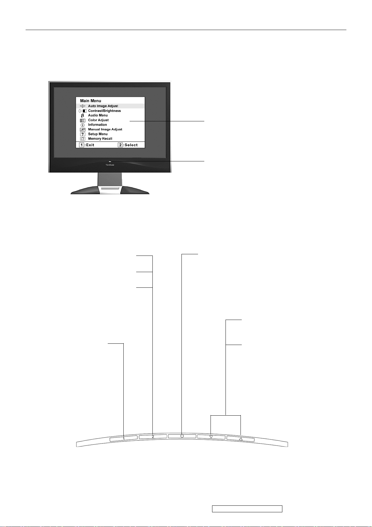
3. Front Panel Function Control Description
Main Menu
with OSD controls
Front Control Panel
shown below in detail
Displays the control screen for
the highlighted control.
Also toggles between two
controls on some screens.
Also a shortcut to Auto Image
Adjust.
Displays the Main
Menu or exits the
control screen and
saves adjustments.
Standby Power On/Off
Power light
Blue = ON
Orange = Power Saving
Scrolls through menu
options and adjusts the
displayed control.
Also a shortcut to display
the Contrast adjustment
control screen (T) /
OptiColor (S)
8
ViewSonic Corporation Confidential - Do Not Copy VX2235wm-4
Do the following to adjust the display setting:
1. To display the Main Menu, press button [1].
NOTE: All OSD menus and adjustment screens disappear automatically after about 15
seconds. This is adjustable through the OSD timeout setting in the setup menu.
2. To select a control to adjust, pressSorTto scroll up or down in the Main Menu.
3. After the desired control is selected, press button [2]. A control screen like the one shown
below appears.
The command line at the bottom of the
control screen tells what to do next from
this screen. You can toggle between control
screens, adjust the selected option, or exit
the screen.
4. To adjust the setting, press the up S or down T buttons.
5. To save the adjustments and exit the menu, press button [1] twice.
The following tips may help you optimize your display:
• Adjust the computer's graphics card so that it outputs a 1680 x 1050 @ 60Hz video signal to
the LCD display. (Look for instructions on “changing the refresh rate” in the graphics card's
user guide.)
• If necessary, make small adjustments using H. POSITION and V. POSITION until the
screen image is completely visible. (The black border around the edge of the screen should
barely touch the illuminated “active area” of the LCD display.)
9
ViewSonic Corporation Confidential - Do Not Copy VX2235wm-4
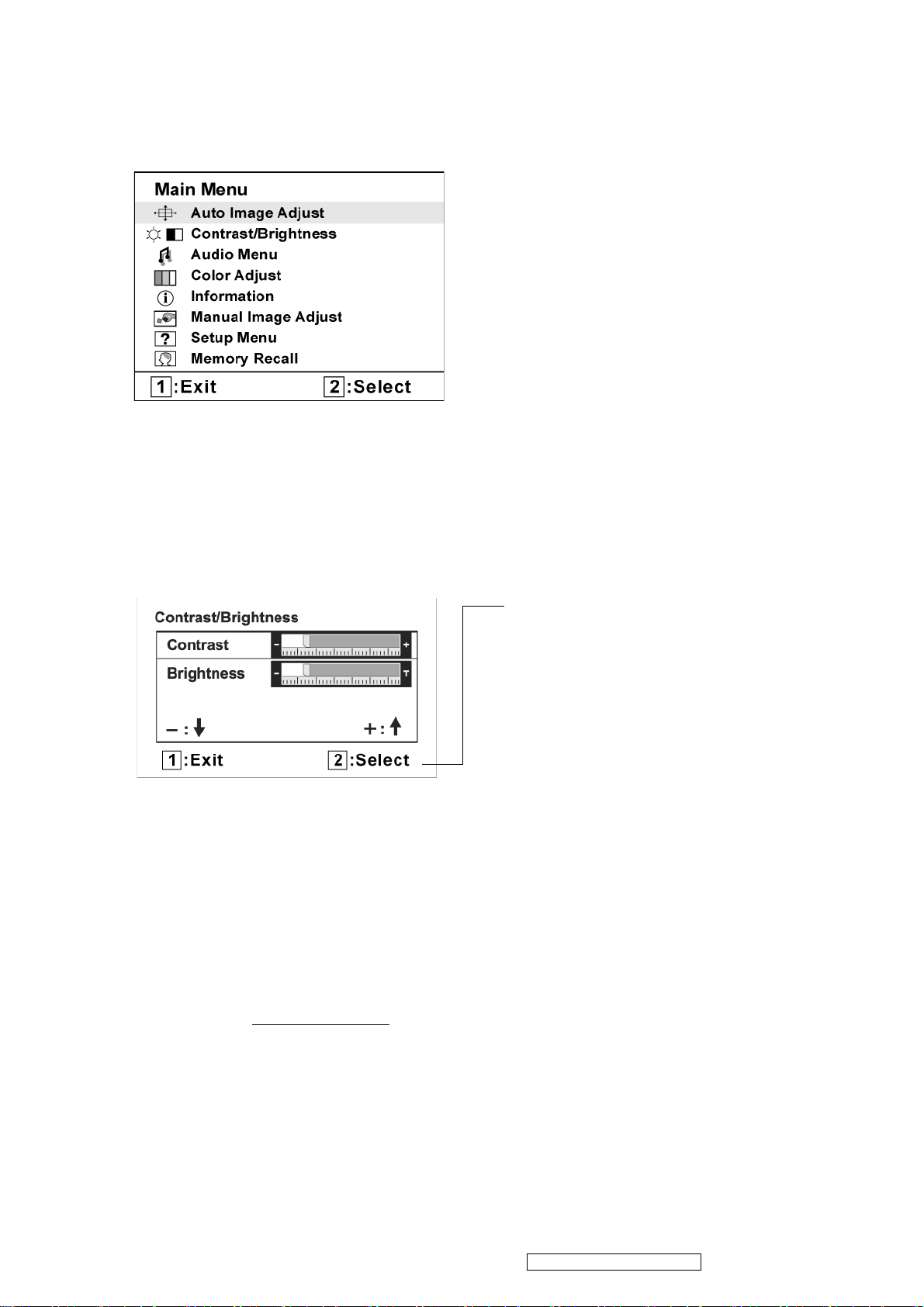
Main Menu Controls
Adjust the menu items shown below by using the up S and down T buttons.
Control Explanation
Auto Image Adjust sizes and centers the screen image automatically.
Contrast adjusts the difference between the image background (black level)
and the foreground (white level).
Brightness adjusts background black level of the screen image.
Audio Adjust
Vol ume increases the volume, decreases the volume, and mutes the audio.
Mute temporarily silences audio output.
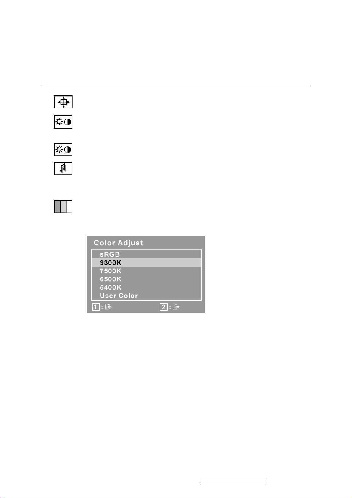
Color Adjust provides several color adjustment modes, including preset color
temperatures and a User Color mode which allows independent adjustment of
red (R), green (G), and blue (B). The factory setting for this product is 6500K
(6500 Kelvin).
sRGB-This is quickly becoming the industry standard for color management,
with support being included in many of the latest applications. Enabling this
setting allows the LCD display to more accurately display colors the way they
were originally intended. Enabling the sRGB setting will cause the Contrast and
Brightness adjustments to be disabled.
9300K-Adds blue to the screen image for cooler white (used in most office
settings with fluorescent lighting).
7500K - Adds blue to the screen image for cooler white (used in most office
settings with fluorescent lighting).
6500K-Adds red to the screen image for warmer white and richer red.
5400K-Adds green to the screen image for a darker color.
10
ViewSonic Corporation Confidential - Do Not Copy VX2235wm-4
Control Explanation
User Color Individual adjustments for red (R), green (G), and blue (B).
1. To select color (R, G or B) press button [2].
2. To adjust selected color, pressSandT.
Important: If you select RECALL from the Main Menu when the product is
set to a Preset Timing Mode, colors return to the 6500K factory preset.
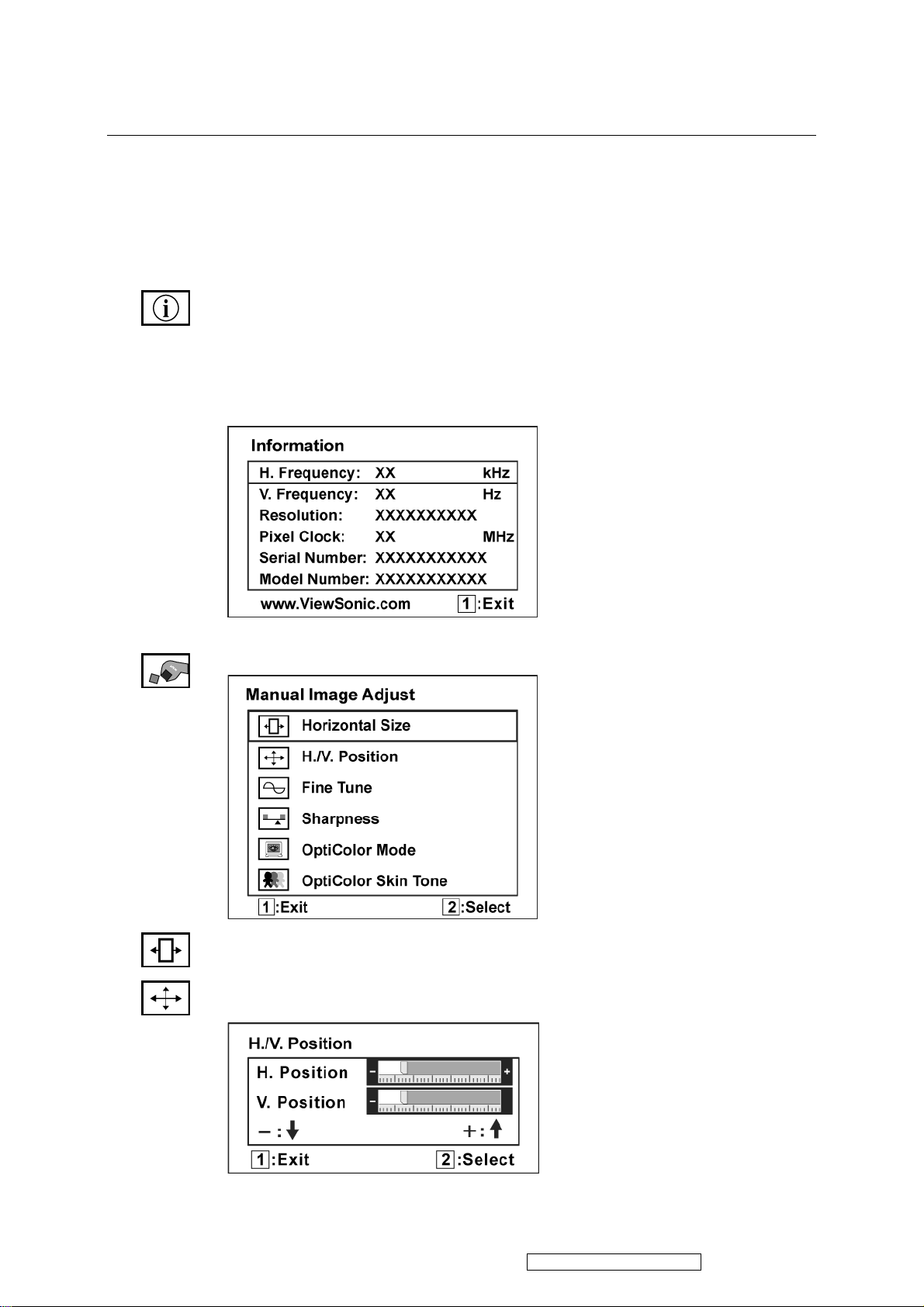
Information displays the timing mode (video signal input) coming from the
graphics card in the computer, the LCD model number, the serial number, and
the ViewSonic® website URL. See your graphics card’s user guide for
instructions on changing the resolution and refresh rate (vertical frequency).
NOTE: VESA 1680 x 1050 @ 60Hz (recommended) means that the resolution
is 1680 x 1050 and the refresh rate is 60 Hertz.
Manual Image Adjust
Horizontal Size adjusts the width of the screen image.
H./V. Position (Horizontal/Vertical Position) moves the screen image left or
right and up or down.
11
ViewSonic Corporation Confidential - Do Not Copy VX2235wm-4
Control Explanation
Fine Tune sharpens the focus by aligning text and/or graphics with pixel
boundaries.
NOTE: Try Auto Image Adjust first.
Sharpness adjusts the clarity and focus of the screen image.
OptiColor Mode provides an optimum display environment depending on the
contents displayed. It contains 7 user-selectable presets. These 7 presets are
easily accessible from the short cut keys.
Standard is for general windows environment and monitor default setting.
Tex t optimized for text editing and viewing in a word processing environment.
Cinema optimized for movie and video environment.
Game optimized for PC/TV game environment.
Portrait optimized for displaying indoor portraits and enhancing pictures.
Scenery optimized for displaying outdoor scenery images.
Vivid optimized for color luster and sharpness.
These 7 presets are carefully chosen by Viewsonic, but may not suit all users'
tastes. In that case, the user can either return to the Standard setting and
manually adjust the brightness and contrast as desired.
OptiColor Skin Tone includes 3 presets (Natural / Red Tone / Yellow Tone)
which user can select according to user's preference.
12
ViewSonic Corporation Confidential - Do Not Copy VX2235wm-4
Control Explanation
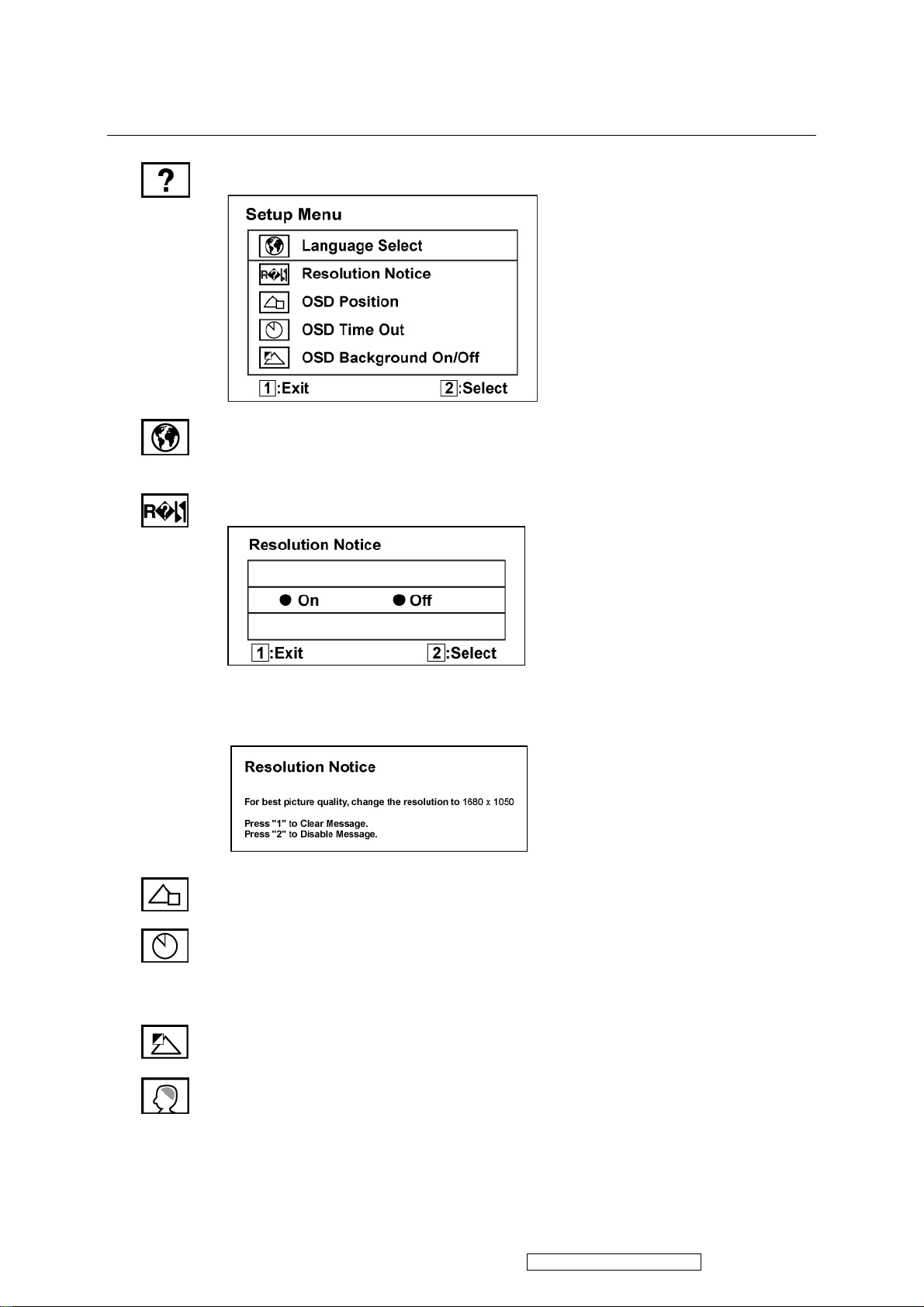
Setup Menu displays the menu shown below:
Language Select allows the user to choose the language used in the menus and
control screens.
Resolution Notice allows the user to enable or disable this notice.
If you enable the Resolution Notice shown above and your computer is set at a
resolution other than 1680 x 1050, the following screen appears.
OSD Position allows the user to move the OSD menus and control screens.
OSD Timeout sets the length of time the OSD screen is displayed. For example,
with a “30 second” setting, if a control is not pushed within 30 seconds, the
display screen disappears.
OSD Background allows the user to turn the OSD background On or Off.
Memory Recall returns the adjustments back to factory settings if the display is
operating in a factory Preset Timing Mode listed in the Specifications of this
manual.
13
ViewSonic Corporation Confidential - Do Not Copy VX2235wm-4

4. Circuit Description
RTD2553V
LCD Monitor/MFM Controller
General
Embedded dual DDC with DDC1/2B/CI
Zoom scaling up and down
No external memory required.
Require only one crystal to generate all timing.
Programmable 3.3V/5V detection reset output.
Embedded crystal output to micro -controller.
3 channels 8 bits PWM output, and wide range selectable PWM frequency.
Analog RGB Input Interface
Integrated 8 -bit triple-channel 210/165 (optional) MHz ADC/PLL
Embedded programmable Schmitt trigger of HSYNC
Support Sync On Green (SOG) and various kinds of composite sync modes
On -chip high-performance hybrid PLLs
High resolution true 64 phase ADC PLL
Y/Pb/Pr support up to HDTV 1080i resolution
Support 2/1 Analog input (optional )
Digital Video Input Interface
Support 8 -bit video (ITU 656) format input
Support 16 -bit video (ITU 601) format input (optional)
Built -in YUV to RGB color space converter & de-interlace
DVI Compliant Digital Input Interface (optional)
Single l ink on-chip TMDS receiver
Support to 165Mhz with long cable
Adaptive algorithm for TMDS capability
Data enable only mode support
High -Bandwidth Digital Content Protection (HDCP 1.1) (optional only in H version)
Enhanced protection of HDCP se cret key (optional only in H version)
Auto Detection /Auto Calibration
Input format detection
Compatibility with standard VESA mode and support user-defined mode
Smart engine for Phase/Image position/Color calibration
Scaling
Fully programmable zoom ratios
Independent horizontal/vertical scaling
Advanced zoom algorithm provides high image quality
Sharpness/Smooth filter enhancement
Support non -linear scaling from 4:3 to 16:9 or 16:9 to 4:3
Vivid Color.
Dynamic Contrast Control (DC C)
Independent Color Management (ICM)
True 10 bits color processing engine
sRGB compliance
Advanced Dithering logic for 18 -bit panel color depth enhancement
Dynamic overshoot -smear canceling engine
Brightness and contrast control
Progr ammable 10-bit gamma support
Output Interface
Fully programmable display timing generator
Flexible data pair swapping for easier system design.
Programmable TCON function support
Multi -output interface (RSDS/LVDS/TTL)on single PCB
Spread -Spectrum DPLL to reduce EMI
Fixed Last Line output for perfect panel capability
Host Interface
Support MCU serial/parallel bus interface.
Support MCU dual edge data latch.
14
ViewSonic Corporation Confidential - Do Not Copy VX2235wm-4

Embedded OSD
Embedded 12K SRAM dynamically stores OSD command and fonts
Supp ort multi-color RAM font, 1, 2 and 4-bit per pixel
16 color palette with 24bit true color selection
Maximum 8 window with alpha -blending/gradient/dynamic fade-in/fade-out, bordering/shadow/3D
window type
Rotary 90,180,270 degree
Independent r ow shadowing/bordering
Programmable blinking effects for each character
OSD -made internal pattern generator for factory mode
Support 12x18~4x18 proportional font
Decompress OSD font
Power & Technology
3.3V power supplier
0.18um CMOS process, 12 8-pin QFP package
Embedded 3.3V to 1.8V voltage regulator
Analog Input
RTD integrates three ADC's (analog-to-digital converters), one for each color (red, green, and blue).
The sync-processor can deal with Separate-Sync, Composite-Sync, and Sync-On-Green. And the PLL
can generate very low jitter clock from HS to sample the analog signal to digital data. Input data is
latched within a capture window defined in registers refer to VS and HS leading edge. RTD also has 2
ADC input, we can switch these 2 input to choose which input we want to present on RTD embedded
LCD monitor.
RTD has a YPbPr input, we can connect DVD or some devices that has YPbPr input, YPbPr input can
be 1st or 2nd ADC pins.
TMDS Input
RTD integrates high-speed single link receiver function. It can operate up to 165 M at long cable. RTD
integrates an equalizer to enhance the cable loss weakness in long cable application and the advanced
tracking algorithm to have better performance in DVI RX.
Display Output Timing
The display output port sends single/double pixel data transfer and synchronized display timing to an
external device. The display port also support display panel with 6-bit per color, turn on the dithering
function to enhance color depth. In single pixel output mode, single pixel data (24-bit RGB) is
transferred to display port A on each active edge of DCLK, the rate of DCLK is also equal to display
pixel clock. The sync & enable signals are also sent to display port on each active edge of DCLK. In
double pixel output mode, double pixel data (48-bit RGB) is transferred to display port A & B on each
active edge of DCLK and the rate of DCLK is equal to half display pixel clock at this moment.
The sync & enable signals are also sent to display port on each active edge of DCLK.
Color Processing
Digital color R & G & B independent channel sRGB, contrast, brightness, gamma, dithering controls
are built in RTD. sRGB compliance function is provided with 9 multipliers. The contrast control is
performed a multiply value from 0 to 2 for each R/G/B channel. The brightness control is used to set an
offset value from –512 to +511 also for each R/G/B channel. Also RTD provided 10 bit gamma and a
high performance dithering function.
Build-In OSD
The detailed function-description of build-in OSD, please refer to the application note for RTD
embedded OSD.
Color LUT & Overlay Port
The following diagram presents the data flow among the gamma correction, dithering, overlay MUX,
OSD LUT and output format conversion blocks.
Auto-Adjustment
There are two main independent auto-adjustment functions supported by RTD, including
auto-position & auto-tracking. The operation procedure is as following;
15
ViewSonic Corporation Confidential - Do Not Copy VX2235wm-4

Auto-Position
1. Define the RGB color noise margin: When the value of color channel R or G or B is greater than
these noise margins, a valid pixel is found.
2. Define the threshold-pixel for vertical boundary search
3. Define the boundary window of searching for horizontal boundary search.
4. Start auto-function.
5. The result can be read from register.
Auto-Tracking
1. Setting the control-registers for the function (auto-phase, auto-balance) according to the
Control-Table.
2. Define the Threshold
3. Define the boundary window of searching for tracking window.
4. Start auto-function.
5. The result can be read from register
PLL System
Inside the RTD, there are four PLL systems for display clock and ADC sample clock (PLL1,
PLL2,M2PLL, DPLL ).
DCLK PLL
DPLL frequency = F_IN * DPM / DPN * Divider.
F_IN is input crystal frequency. DPM and DPN is in DPLL_M and DPLL_N.
DPLL_N, and it divide PLL frequency by 1, 2, 4 or 8.
According to parameter DPN, you must set LPF Mode in DPLL_WD. If LPF Mode is 1, the charge
pump current, Ich, must be DPM/17.6, while Ich must be DPM/1.67 if LPF Mode is 0. The charge
pump current Ich is in DPLL_CRNT.
Spread-Spectrum function is also build in DCLK to reduce EMI. You can control the SSP_I, SSP_W,
and FMDIV to fine-tune the EMI.
M2PLL is a PLL used to power-on reset, FIFO clock and Internal crystal clock. After power-on reset,
M2PLL output 10 times frequency of crystal clock. According to crystal frequency, set M2PLL to keep
FIFO clock frequency between 240MHz and 250MHz.
ADC Pixel Sampling PLL
The input pixel sampling PLL of RTD compose of PLL1 and PLL2 and DDS, the hybrid PLL system
inherently has a process-independent advantages comparing with pure analog PLL, DDS synthesizer is
in charge of the phase-frequency control, PLL1 provided a high frequency to get a larger bandwidth
letting the system fast locking, PLL2 finally synthesize the desired pixel sampling clock. The block
diagram shown below describes our high-performance tracking system.
Host Interface
Parallel/Serial Port Determination:
After RESET end, the status of pin 5 (TMDS_TST) can be sensed to determine the interface mode:
high for parallel port, low, low for serial port.
Host Interface Location Determination:
After the falling edge of RESET signal, the status of pin 3 can be sensed to determine the host interface
location: high for 112-115,118,119, and low for 52-57
Reset Output
We have the RESET_OUT function, and also reserve the RESET_IN function. By the bounding of
internal pins we can select two kinds of reset function. First of all is only reset-out, we can output the
reset signal to MCU, and the MCU can reset the RTD by firmware. The second is RTD output reset and
also reset itself. Notice that the reset output is positive polarity, besides, the reset output is open-drain
pin, please don’t forget to attach a pull-up resistor (10K). The reset function for 3.3V operating
voltage detection is determined by 33VRST_REF voltage, No matter 5V or 3.3V MCU is been used,
divider the input voltage on 33VRST_REF to 2.2V for internal power sensing circuit detecting, the
divider resistor should be 10K level avoiding current leakage.
The Programmable Schmitt Trigger of HSYNC
To get better waveform of the input HSYNC, we have a programmable Schmitt Trigger circuit. For
different HSYNC amplitude and polarity, we can select different setting of the threshold voltage. The
Vt + and the Vt - can be selected by register CR97 We can select the old mode or the new mode. When
using the new mode we can directly determine the positive threshold voltage (1.4V, 1.6V… 2.6V), and
we can choose the hysterias from
the Vt + to determine the Vt - (0.6V, 0.8V, 1.0V, 1.2V). We also can finely tune the voltage by minus
0.1V. For application, we can select different threshold voltage by the polarity of the HSYNC. The
control register is CR97
16
ViewSonic Corporation Confidential - Do Not Copy VX2235wm-4

Crystal Frequency Output
RTD can output crystal frequency or 1/2 crystal frequency to external MCU to save a crystal device.
Once power state is on and reset is finished, we can set crystal frequency by firmware and output to pin
48 and pin 110 simultaneously, and then can turn off them in Pin Share Part. Pin 48 and PIN 110 is
configurable, detail setting is listed in Pin-Share part
RTD2120 8051 Embedded Micro-Controller for Monitor
Overview
This chip is the micro-processor of LCD monitor. It uses the design ware DW8051 of
Synopsys as the 8051 core of this chip and is compatible with other industry 8051 series. Also,
96Kbyte FLASH with 8 bit bus is embedded in this chip which is licensed from TSMC 0.18um
e-FLASH process. Here we use the package of PLCC44/LQFP48 if we would like to have a
discrete MCU controller or we make a multi-chip package with our LCD monitor controller to
form one chip package to save the cost of package and PCB material.
Features
Operating voltage range : 3.0V to 3.6V
8051 core, CPU operating frequency up to 50MHz
4 clocks per machine cycle
256-byte internal RAM
512-byte external data RAM, including 256-byte DDC RAM(128-byte x 2) and 256-byte
general purpose RAM
96K-byte flash memory, 64k for program and 32k for saving parameter
Two DDC ports compliant with VESA DDC1/2B/2Bi/CI
Three channels of PWM DAC with programable frequency from 100K to 100Hz
Watchdog timer with programmable interval
Three 16-bit counters/timers (T0, T1, and T2)
One PLL to provide programmable operating frequency and clock output, 2 clock output ports
One full-duplex serial port
Six interrupt sources with 2 external interrupts
zFour channels of 6-bit ADC
zHardware In System Programming(ISP) capability, no boot code required
zBuilt-in Low voltage reset circuit
zEmbedded 1.8V regulator
zCode protection
zAvailable in 44-pin PLCC or 48-pin LQFP package
AUDIO STEREO CLASS-D AUDIO POWER AMPLIFIER
DESCRIPTION
The TPA2008D2 is a third generation 5-V class-D amplifier from Texas Instruments. Improvements to
previous generation devices include: dc volume con-trol, lower supply current, lower noise loor ,higher
efficiency, smaller packaging, and fewer external components. Most notably, a new filter-free class-D
modulation technique allows the TPA2008D2 to directly drive the speakers, without needing a low-pass
output filter consisting of two inductors and three capacitors per channel. Eliminating this output filter
saves approximately 30% in system cost and 75% in PCB area.
The improvements and functionality make this device ideal for LCD projectors, LCD on itors ,powered
speakers, and other applications that demand more battery life, reduced board space, and functionality
that surpasses currently available class-D devices.
A chip-level shutdown control limits total supply current to 1 µA, making the device ideal for bat-
Tery powered applications. Protection circuitry in-creases device reliability: thermal and short circuit.
Under voltage shutdown saves battery power for more essential devices when battery voltage drops to
low leve.
17
ViewSonic Corporation Confidential - Do Not Copy VX2235wm-4
5. Adjustment Procedure
1. Function Test
1.1 Product
- 22” LCD Monitor
1.2 Test Equipment
- Color Video Signal & Pattern (or PC with WSXGA+ resolution and a sound card)
1.3 Test Condition
Before function test and alignment, each LCD Monitor should be run-in and warmed up for at least
30 minutes with the following conditions:
(a) In room temperature,
(b) With full-white screen, RGB, and Black
(c) With cycled display modes,
640*480 (H=43.27kHz, V=85Hz)
800*600 (H=53.7kHz, V=85Hz)
1024*768 (H=68.67kHz, V=85Hz)
1680*1050 (H=64.7kHz, V=60Hz)
1.4 Test Display Modes & Pattern
1.4.1 Compatible Modes
Analog Digital
1. 640 x 350 @ 70Hz, 31.5kHz
2. 640 x 400 @ 60Hz, 31.5kHz
3. 640 x 400 @ 70Hz, 31.5kHz
4. 640 x 480 @ 50Hz, 24.7kHz
5. 640 x 480 @ 60Hz, 31.5kHz
6. 640 x 480 @ 67Hz, 35.0kHz
7. 640 x 480 @ 72Hz, 37.9kHz
8. 640 x 480 @ 75Hz, 37.5kHz
9. 640 x 480 @ 85Hz, 43.27kHz
10. 720 x 400 @ 70Hz, 31.5kHz
11. 720 x 480 @ 60Hz, 31.5kHz
12. 720 x 576 @ 50Hz, 31.3kHz
13. 800 x 600 @ 50Hz, 24.7kHz
14. 800 x 600 @ 56Hz, 35.1kHz
15. 800 x 600 @ 60Hz, 37.9kHz
16. 800 x 600 @ 70Hz, 43 kHz
17. 800 x 600 @ 72Hz, 48.1kHz
18. 800 x 600 @ 75Hz, 46.9kHz
19. 800 x 600 @ 85Hz, 53.7kHz
20. 832 x 624 @ 75Hz, 49.7kHz
21. 1024 x 768 @ 50Hz, 39.6kHz
22. 1024 x 768 @ 60Hz, 48.4kHz
23. 1024 x 768 @ 70Hz, 56.5kHz
24. 1024 x 768 @ 72Hz, 58.1kHz
25. 1024 x 768 @ 75Hz, 60 kHz
26. 1024 x 768 @ 85Hz, 68.7 kHz
27. 1152 x 864 @ 75Hz, 67.5 kHz
28. 1152 x 870 @ 75Hz, 68.7 kHz
640 x 350 @ 70Hz, 31.5kHz
640 x 400 @ 60Hz, 31.5kHz
640 x 400 @ 70Hz, 31.5kHz
640 x 480 @ 50Hz, 24.7kHz
640 x 480 @ 60Hz, 31.5kHz
640 x 480 @ 67Hz, 35.0kHz
640 x 480 @ 72Hz, 37.9kHz
640 x 480 @ 75Hz, 37.5kHz
640 x 480 @ 85Hz, 43.27kHz
720 x 400 @ 70Hz, 31.5kHz
720 x 480 @ 60Hz, 31.5kHz
720 x 576 @ 50Hz, 31.3kHz
800 x 600 @ 50Hz, 24.7kHz
800 x 600 @ 56Hz, 35.1kHz
800 x 600 @ 60Hz, 37.9kHz
800 x 600 @ 70Hz, 43 kHz
800 x 600 @ 72Hz, 48.1kHz
800 x 600 @ 75Hz, 46.9kHz
800 x 600 @ 85Hz, 53.7kHz
832 x 624 @ 75Hz, 49.7kHz
1024 x 768 @ 50Hz, 39.6kHz
1024 x 768 @ 60Hz, 48.4kHz
1024 x 768 @ 70Hz, 56.5kHz
1024 x 768 @ 72Hz, 58.1kHz
1024 x 768 @ 75Hz, 60 kHz
1024 x 768 @ 85Hz, 68.7 kHz
1152 x 864 @ 75Hz, 67.5 kHz
1152 x 870 @ 75Hz, 68.7 kHz
18
ViewSonic Corporation Confidential - Do Not Copy VX2235wm-4
 Loading...