

ViewSonic VX1945wm-3 Service manual

Service Manual
ViewSonic VX1945wm-3
Model No. VS11444
19” Color TFT LCD Display
(VX1945wm-3_SM Rev. 1a Nov. 2006)
ViewSonic 381 Brea Canyon Road, Walnut, California 91789 USA - (800) 888-8583
Copyright
Copyright © 2006 by ViewSonic Corporation. All rights reserved. No part of this publication
may be reproduced, transmitted, transcribed, stored in a retrieval system, or translated into any
language or computer language, in any form or by any means, electronic, mechanical, magnetic,
optical, chemical, manual or otherwise, without the prior written permission of ViewSonic
Corporation.
Disclaimer
ViewSonic makes no representations or warranties, either expressed or implied, with respect to
the contents hereof and specifically disclaims any warranty of merchantability or fitness for any
particular purpose. Further, ViewSonic reserves the right to revise this publication and to make
changes from time to time in the contents hereof without obligation of ViewSonic to notify any
person of such revision or changes.
Trademarks
Optiquest is a registered trademark of ViewSonic Corporation.
ViewSonic is a registered trademark of ViewSonic Corporation.
All other trademarks used within this document are the property of their respective owners.
Revision History
Revision SM Editing Date ECR Number Description of Changes Editor
1a 11/7/2006 Initial Release Jamie Chang
ViewSonic Corporation Confidential - Do Not Copy VX1945wm-3
i
TABLE OF CONTENTS
1. Precautions and Safety Notices 1
2. Specification 4
3. Front Panel Function Control Description 14
4. Circuit Description 26
5. Adjustment Procedure 36
6. Troubleshooting Flow Chart 45
7. Recommended Spare Parts List 53
8. Exploded Diagram and Exploded Parts List 55
9. Block Diagram 59
10. Schematic Diagrams 60
11. PCB Layout Diagrams 67
ViewSonic Corporation Confidential - Do Not Copy VX1945wm-3
ii

1. Precautions and Safety Notices
1. SAFETY PRECAUTIONS
This monitor is manufactured and tested on a ground principle that a user’s safety comes first. However,
improper used or installation may cause damage to the monitor as well as to the user.
WARNINGS:
This monitor should be operated only at the correct power sources indicated on the label on the rear
of the monitor. If you’re unsure of the power supply in you residence, consult your local dealer or
Power Company.
Use only the special power adapter that comes with this monitor for power input.
Do not try to repair the monitor by yourself, as it contains no user-serviceable parts. Only the
qualified technician can repair it.
Do not remove the monitor cabinet. There are high-voltage parts inside that may cause electric shock
to human bodies.
Stop using the monitor if the cabinet is damaged. Have it checked by a service technician.
Put your monitor only in a lean, cool, dry environment. If it gets wet, unplug the power cable
immediately and consult your closed dealer.
Always unplug the monitor before cleaning it. Clean the cabinet with a clean, dry cloth. Apply
non-ammonia based cleaner onto the cloth, not directly onto the glass screen.
Do not place heavy objects on the monitor or power cord.
2. PRODUCT SAFETY NOTICE
Many electrical and mechanical parts in this chassis have special safety visual inspections and the
protection afforded by them cannot necessarily be obtained by using replacement components rated for
higher voltage, wattage, etc. Before replacing any of these components read the parts list in this manual
carefully. The use of substitute replacement parts, which do not have the same safety characteristics as
specified in the parts list, may create shock, fire, or other hazards.
3. SERVICE NOTES
When replacing parts or circuit boards, clamp the lead wires around terminals before soldering.
Keep wires away from high voltage, high temperature components and sharp edges.
Keep wires in their original position so as to reduce interference.
Adjustment of this product please refers to the user’ manual.
ViewSonic Corporation Confidential - Do Not Copy VX1945wm-3
1
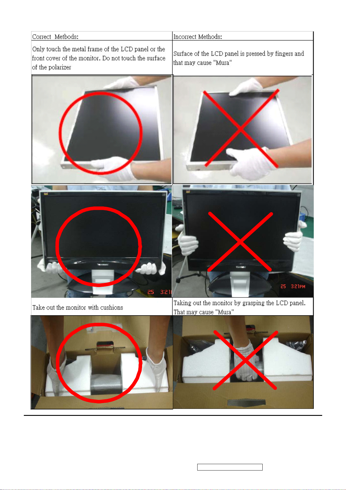
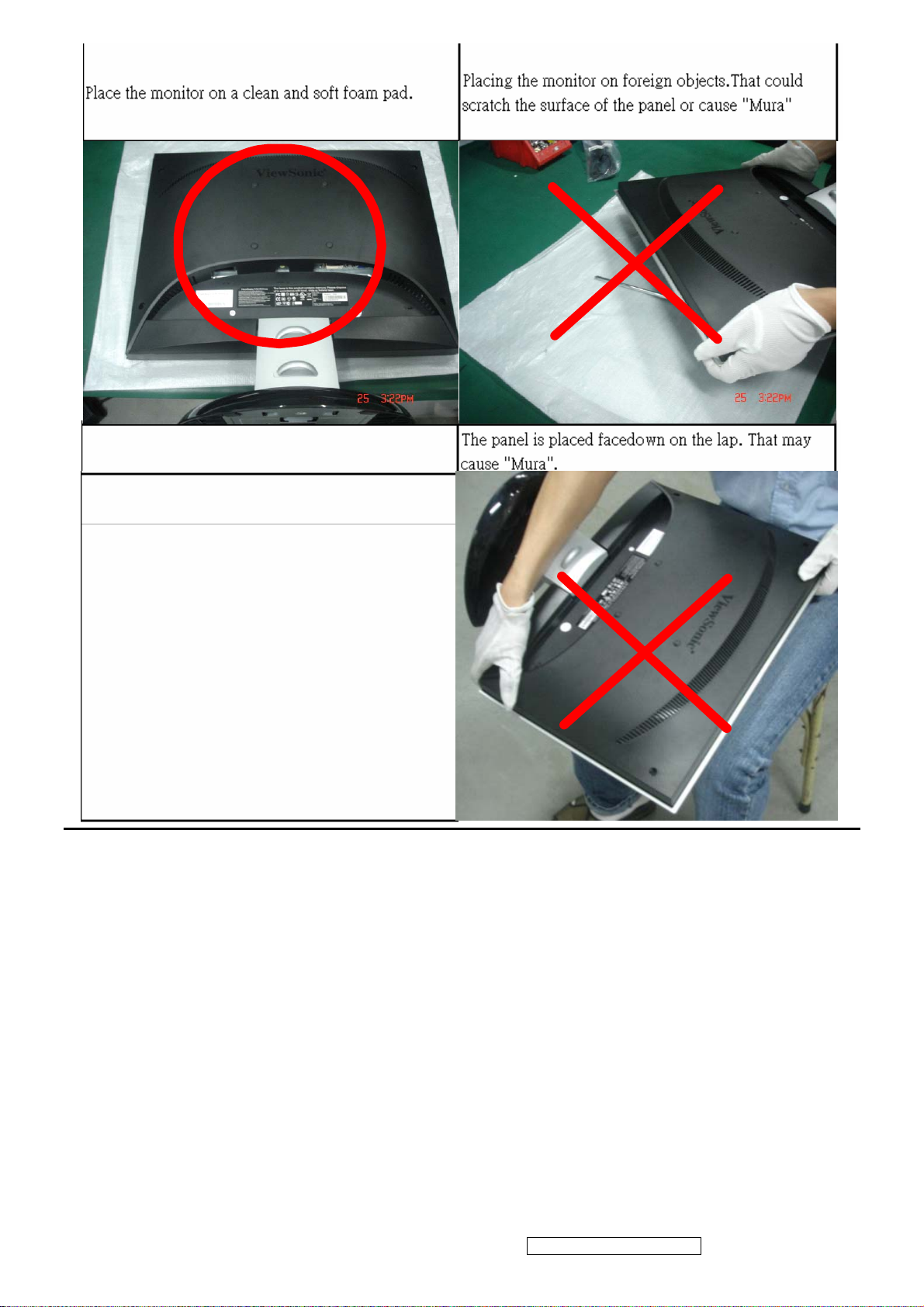
5.2 Handling and Placing Methods
ViewSonic Corporation Confidential - Do Not Copy VX1945wm-3
2
ViewSonic Corporation Confidential - Do Not Copy VX1945wm-3
3
2. Specification
2.1. INTRODUCTION
FEATURES VX1945wm-3
Size
TFTLCD PANEL
Luminance (Typ)
1st
Contrast Ratio (Typ) 700:1
Colors 16.2 M (6 bits + 2 bits FRC)
Innolux
Response Time 5 ms(on/off)
MT190AW01 V.0
Viewing Angle (H/V) 160 ° / 160 °
Recommend resolution 1440x900@60Hz
Video
Input Signal
Audio
Output Signal Audio
Separate Sync Yes
Sync Compatibility
Composite Sync Yes
Sync on Green Yes
Analog (Head)
Digital (Head)
3.5 mm Audio in (Head)
3.5mm 2 in 1 Audio in (Base)
3.5 Audio out (Base)
Headphone out (Base)
19 " wide
300 cd/㎡
Yes (75ohms, 0.7/1.0 Vp-p)
Yes
Yes
Yes
Yes
Yes
PC Yes
Compatibility
Power Mac Yes
TV Box (NextVision 6) Yes
Power Voltage AC 100-240V, 50/60Hz Yes
Power
Consumption
LCD
On Mode(Typ)
Off Mode (Max)
On Mode(Typ)
Multimedia base
On Mode (Max)
< 48 W
1 W≦
< 24 W
30 W≦
Upstream port (B type) X 1 Yes
USB
Downstream port (A type) X 4 Yes
Card reader 8 in 1 Function
Audio 2.1 CH - THD 10% (Max)
(Sat.: 2.5w x2 ; subwoofer:3w x1)
Tilt ( 20 ° - -5 °)
SD/MMC/MS/MS PRO/CF I & II /MicroDrive/SM
Yes
Yes
Swivel No
Ergonomics
Pivot No
Height Adjust No
OSD Control [ 1 ] [ 2 ] [ ][▼] [▲] Yes
Physical (W x H x D) 450 x 434 x 209mm
Dimension
Package (W x H x D) 545*515*162mm
Weight Physical (Net Weight) 5.2 Kg / 11.5 lbs
ViewSonic Corporation Confidential - Do Not Copy VX1945wm-3
4
Package (Gross Weight) 6.7 Kg / 14.8 lbs
Temperature (℉/℃) 32℉-104℉ / 0℃-40℃ Operating
Condition
Humidity (%) 20 % - 80 %
Temperature (℉/℃) -4℉-140℉ / -20℃-60℃
Storage Condition
Humidity (%) 10% - 90 %
Global: CB, MPR II, WEEE,ROHS , ISO13406-2
VSA:UL, cUL, FCC-B, TUV-S, NOM, Energy Star
Regulation
VSE:TUV/ERGO,CE ,GOST-R+Hygienic ,SASO , ENERGY
VSI: BSMI, CCC, PSB, C-TICK, MIC
VSCN:CCC
ViewDock – Multimedia base Spec.
Device prococal
USB Standards
Compatible Operating
Systems
OHCI (Open Host Controller Interface)
EHCI (Enhanced Host Controller Interface)
USB 2.0 Speed
USB 1.x Speed
Mac OS X with USB 2.0 Support
Microsoft Windows XP/Me/2000/98SE with USB 2.0 Support
Mac OS 8.6 or above with USB 1.x Support and USB Card Support
USB 2.0/1.1
USB Hub
USB Supplied Current
Card Reader
4 slots
1.4.1
Microsoft Windows XP/Me/2000/98SE with USB 1.x Support
Upstream
Downstream
Self-Powered Mode: 500mA /Port
Secure Digital (SD)
Multi Media Card (MMC)
Compact Flash (CF) Type I
Micro Drive
Smart Media (SM)
Memory Stick (MS)
Memory Stick Pro (MS Pro)
XD
1 Upstream USB Type B Receptacle
4 Downstream USB Type A Receptacles
Idle Mode : 5mA /Port
Operating Mode: 100mA/Port
Compact Flash (CF) Type II
SMC/XD and SD/MMC
CF Type I/II and MS/MS Dual/MS Pro
3.0W (typ) ; 5.0W (Max)
Φ46mm
>85dB
Audio / Speaker
Upper Slot
Lower Slot
Subwoofer
Nominal size
S/N
ViewSonic Corporation Confidential - Do Not Copy VX1945wm-3
5
THD
< 10% (Vol. Max)
MIC
VR Volume control
Audio I/O
iPOD connector
Power adapter External
Size
Connectivity
S/N
Sensitivity:
Input
Output
303mm (W) x 212mm (L)
Up to 127 Devices by Cascading Multiple Hubs
Power on
60dB (Built-in)
-38dB +- 3dB
Rotation stopper strength: 1.0Kgf.cm
Total rotational angle: 220+
2-in-1 Audio-in x 1 (Audio-in / MIC-in)
Audio-out x1 , Headphone out x1
Compatible with iPOD video/iPOD photo/iPOD nano/iPOD Mini/iPOD
U2/iPOD
Input Voltage Range: 100~240V
Input Frequency: 50/60Hz
Output Voltage: 12V
Full load: 2.0A
Peak load: 2.5A
Yellow-Green
5˚
iPod connecting
Diagnostic LEDs
Power consumption Typical
Max.
Storage Temperature
Storage Humidity
Operating Temperature
Opreating Humidity
Certifications
Accessories
iPod
connecting+Power
on
-4ºF to 140ºF (-20ºC to 60ºC)
10% to 90% (Non-Condensing)
32ºF to 104ºF (0ºC to 40ºC)
20% to 90% (Non-Condensing)
Global: CB, WEEE,ROHS
Amber
Yellow-green+Amber
24W
30W
VSA:UL, cUL, FCC-B, TUV-S, NOM
VSE:CE ,GOST-R+Hygienic ,SASO
VSI:BSMI, CCC, PSB, C-TICK, MIC
VSCN:CCC
USB A-B Cable ; 2-in-1 Cable ; Power adaptor ; iPod adapter set
(default x 1; 4 in set)
Package content
Viewdock/Quick start guide/CD(for card reader windows 98
driver)/2-in-1 Aduio cable/USB cable/Power adapter/iPod adapter set
ViewSonic Corporation Confidential - Do Not Copy VX1945wm-3
6
2.2. GENERAL specification
Test Resolution & Frequency 1440x900 @ 60Hz
Test Image Size Full Size
Contrast and Brightness Controls
Factory Default:
Contrast = 70%, Brightness = 100%
2.3. VIDEO INTERFACE
Analog Input Connector DB-15 (Analog),
Digital Input Connector DVI-D (Digital),
Default Input Connector Defaults to the first detected input
Video Cable Strain Relief
Video Cable Connector DB-15 Pin out Compliant DDC 1/2B
Video Signals
Video Impedance 75 Ohms (Analog), 100 Ohms (Digital)
Maximum PC Video Signal 950 mV with no damage to monitor
Equal to twice the weight of the monitor for five
minutes
1. Video RGB (Analog)
Separate, Composite, and Sync on Green
2. TMDS (Digital)
Maximum Mac Video Signal 1250 mV with no damage to monitor
Sync Signals TTL
DDC 1/2B Compliant with Revision 1.3
Sync Compatibility Separate Sync, Composite Sync, SOG
Video Compatibility
Resolution Compatibility
Exclusions Not compatible with interlaced video
Shall be compatible with all PC type computers,
Macintosh computers, and after market video cards
640 x 350*, 640 x 480, 720 x 400* (640 x 400*), 800 x
600, 832 x 624, 1024 x 768, 1152 x 864, 1152 x 870,
1280 x 720, 1280 x 960, 1280 x 1024 , 1400 x 1050 ,
1440 x 900
* The image vertical size might not be full screen.
But the image vertical position should be at the center.
2.4. POWER SUPPLY
Internal Power Supply Part Number:ILPI-024
Input Voltage Range 90 to 264 VAC (100~240VAC ±10%)
Input Frequency Range 47 to 63 Hertz
Short Circuit Protection Output can be shorted without damage
Over Current Protection 5.0 A typical at 14.0 VDC
ViewSonic Corporation Confidential - Do Not Copy VX1945wm-3
7
Leakage Current 3.5mA (Max) at 254VAC / 60Hz
Efficiency (at 115VAC Full Load) Typical: 80%
Minimum: 75%
Fuse Internal and not user replaceable
Power Output 35 Watts (typ)
Ripple and Noise Ripple: <3%
Max Input AC Current 1.2 Arms @ 100VAC, 0.6 Arms @240VAC
Inrush Current (Cold Start)
Power Supply Cold Start
Power Supply Transient Immunity
Power Supply Line Surge Immunity
Power Supply Missing Cycle Immunity
40 A (max) @ 120VAC
60 A (max) @ 220VAC
Shall start and function properly when under full load,
with all combinations of input voltage, input frequency,
and operating temperature.
Shall be able to withstand an ANSI/IEEE C62.41-1980
6000V 200 ampere ring wave transient test with no
damage.
Shall be able to withstand 1.5 times nominal line
voltage for one cycle with no damage.
Shall be able to function properly, without reset or
visible screen artifacts, when ½ cycle of AC power is
randomly missing at nominal input.
The power supply shall not produce audible noise that
would be detectable by the user. Audible shall
defined to be in compliance with ISO 7779 (DIN
Power Supply Acoustics
EN27779:1991) Noise measurements of machines
acoustics. Power Switch noise shall not be
considered.
Power Saving Operation(Method) VESA DPMS Signaling
Power Consumption
Mode LED Power Consumption
35 W (Typ)
On Green
42 W (max)
Stand By Amber < 2 W
Active Off Off < 1 W
Recovery Time On Mode = N/A, Active Off < 3 sec
ViewSonic Corporation Confidential - Do Not Copy VX1945wm-3
8
2.5. ELECTRICAL REQUIREMENT
Horizontal / Vertical Frequency
Horizontal Frequency
Vertical Refresh Rate
24-83 khz
50 – 85* Hz
Maximum Pixel Clock 140 MHz
Sync Polarity Independent of sync polarity.
Timing Table
Digital - TMDS
SOG
For Analog sync, the image vertical size image
will be not full screen (Still at the center)
For Analog sync, the OSD will be
640x480@60Hz
For Analog sync, the image vertical size image
Item
Timing
1 640 x 350 @ 70 Hz, 31.5 KHz
2 640 x 400 @ 60 Hz, 31.5 KHz
3 640 x 400 @ 70 Hz, 31.5 KHz
Analog
Separated
Composite
Remark
4 640 x 480 @ 50 Hz, 24.7 KHz
5 640 x 480 @ 60 Hz, 31.5 KHz
6 640 x 480 @ 67 Hz, 35 KHz
7 640 x 480 @ 72 Hz, 37.9 KHz
8 640 x 480 @ 75 Hz, 37.5 KHz
9 640 x 480 @ 85 Hz, 43.3 KHz
10 720 x 400 @ 70 Hz, 31.5 KHz
11 720 x 480 @ 60 Hz, 31.5 KHz
12 720 x 576 @ 50 Hz, 31.3 KHz
will be not full screen (Still at the center), And the
OSD will be 640x400/720x400 (primary=
720x400).
For Analog sync, the image vertical size image
will be not full screen (Still at the center), And the
OSD will be 640x400/720x400 (primary=
720x400).
For Analog sync, the information OSD shows
640x480
13 800 x 600 @ 56 Hz, 35.1 KHz
14 800 x 600 @ 60 Hz, 37.9 KHz
15 800 x 600 @ 72 Hz, 48.1 KHz
16 800 x 600 @ 75 Hz, 46.9 KHz
17 800 x 600 @ 85 Hz, 53.7 KHz
18 832 x 624 @ 75 Hz, 49.7 KHz
19 1024 x 768 @ 50 Hz, 39.6 KHz
For Analog sync, Switch 1024x768@50Hz and
ViewSonic Corporation Confidential - Do Not Copy VX1945wm-3
9
1280x768@50Hz by [1]+[2] short cut key
20 1024 x 768 @ 60 Hz, 48.4 KHz
21 1024 x 768 @ 70 Hz, 56.5 KHz
22 1024 x 768 @ 75 Hz, 60 KHz
23 1024 x 768 @ 75 Hz, 60.02 KHz
24 1024 x 768 @ 85 Hz, 68.7 KHz
25 1152 x 864 @ 75 Hz, 67.5 KHz
26 1152 x 870 @ 75 Hz, 68.7 KHz
27 1280 x 768 @ 50 Hz, 39.6 KHz
28 1280 x 768 @ 60 Hz, 47.4 KHz
29 1280 x 768 @ 60 Hz, 47.8 KHz
30 1280 x 768 @ 75 Hz, 60.3 KHz
31 1280 x 960 @ 50 Hz, 49.4 KHz
32 1280 x 960 @ 60 Hz, 60.0 KHz
33 1280 x 960 @ 75 Hz, 75.2 KHz
For Analog sync, Switch 1024x768@50Hz and
1280x768@50Hz by [1]+[2] short cut key
For Analog sync, Switch 1024x768@75Hz and
1280x768@75Hz by [1]+[2] short cut key
34 1280 x 1024 @ 50 Hz, 52.7 KHz
35 1280 x 1024 @ 60 Hz, 64 KHz
36 1280 x 1024 @ 70 Hz, 74.8 KHz
37 1280 x 1024 @ 72 Hz, 76.8 KHz
38 1280 x 1024 @ 75 Hz, 80 KHz
39 1360 x 768 @ 60 Hz, 47.7 KHz
40 1400 x 1050 @ 50 Hz, 54.1 KHz
41 1400 x 1050 @ 60 Hz, 64.7 KHz
42 1400 x 1050 @ 60 Hz, 65.3 KHz
43 1400 x 1050 @ 75 Hz, 82.3 KHz
44 1440 x 900 @ 60 Hz, 55.5 KHz
45 1440 x 900 @ 60 Hz, 55.9 KHz
46 1440 x 900 @ 75 Hz, 70.6 KHz
*1. Tolerance ±2KHz.≧
*2. Any timing not in the list, it should display as normal or show on “OUT OF RANGE” OSD message without
blanking.
*3. The image quality of 85Hz mode might be worse than 75Hz.
ViewSonic Corporation Confidential - Do Not Copy VX1945wm-3
10
2.6
TFT LCD PANEL
Panel Characteristics:
st
1
Source Panel
Model number INNOLUX MT190AW01 V.0
Type TN type with LVDS interface
Active Size 19” WIDE ; 410.4(H) X 256.5(V)
Pixel Arrangement RGB Vertical Stripe
Pixel Pitch 0.285(H) x 0.285(H) mm
GLASS TREATMENT Anti Glare (Hard coating 3H)
# OF BACKLIGHTS 4 CCFL ; Top & Bottom edge side
BACKLIGHT LIFE 40,000 Hours (Min)
Luminance (5-point) –
Condition:
CT = 6500K, Contrast = Max,
Brightness = Max
Brightness Uniformity
Contrast Ratio 700:1 (typ), 500:1 (min)
Color Depth 16.2 million colors (6 bits + 2 bits FRC)
Viewing Angle (Horizontal) @ CR>10
Viewing Angle (Vertical) @ CR>10
Response Time
10%-90% @ Ta=25°C
Panel Defects Please see Panel Quality Specifications.
300 cd/m2 (Typ after 30 minute warm up)
230 cd/m2 (Min after 30 minute warm up)
≧75% Entire Area (min)
Typical: 160º
Minimum: 140º
@ CR>5
Typical: TBD
Minimum: TBD
Typical: 160º
Minimum: 140º
@ CR>5
Typical: TBD
Minimum: TBD
Typical = 5ms (Tr =1.5 ms,Tf =3.5 ms)
Maxmum = 15ms (Tr =
6.5 ms,Tf =8.5 ms)
ViewSonic Corporation Confidential - Do Not Copy VX1945wm-3
11
Function descriptions
OSD Lock short cuts function for the buttons
The OSD lock will be activated by pressing the front panel control buttons "(1), & (▲)" for 10
seconds. If the user then tries to access the OSD by pressing any of the buttons "1", "▼",
"▲", "2" a message will appear on the screen for 3 seconds showing "OSD Locked". The
OSD lock will be deactivated by pressing the front panel control buttons "(1), & (▲)" again for
10 seconds.
Note1: When the OSD is locked will lock all functions, including “Volume” and “Mute”
Note 2: Status bar indicating OSD Lock or Unlock is in progress and when complete it will
indicate “OSD Locked”
Note 3: OSD Lock should not lock Power Button and Power Lock function
Power Lock short cuts function for the buttons
The power button lock will be activated by pressing the front panel control buttons "(1), & (▼)" for
10 seconds. Locking the power button means that the user won't be able to turn off the LCD
while the power button is locked. If the user presses the power button while it is locked, a
message will appear on the screen for 3 seconds showing "Power Button Locked". It also means
that with the power button locked, the LCD would automatically turn back "On" when power is
restored after a power failure. If the power button is not in the locked mode, then power should
return to it's previous state when power is restored after a power failure. The power button lock
will be deactivated by pressing the front panel control buttons "(1), & (▼)" again for 10 seconds.
Note 1: Status bar indicating Power Button lock or unlock is in progress and when complete it
will indicate “Power Button Locked”
Note 2: Power should only be lockable in the “On State”
Memory Recall Actions
Memory Recall action on the analog and digital mode as below
1. Recall white balance to factory setting
2. Set the factory defaults as shown in Section 4-8
3. Clean all the mode setting buffer
4. Execute Auto Image Adjust
Note: Memory Recall should have no effect for Language, Power Lock, User Color Settings or
Input Priority
Resolution Notice Actions
Resolution Notice OSD should show on screen after changing to non-native mode for 30 sec
For auto input select function, it shall meet the requirement in Appendix D.
The OSD should disappear after 10 sec or by pushing button [1] or [2]
Resolution Notice function should be disabled when push button [2] under Resolution Notice
OSD
0-Touch™ Function Actions
1. Execute Auto Image Adjust when new mode detected, and save the settings to buffer for
ViewSonic Corporation Confidential - Do Not Copy VX1945wm-3
12
further use
2. It should be reset by Memory Recall function(Should not reset by power off, power unplug and
others)
OSD Auto Save
The OSD shall save new settings when it is turned off by the user or when it times out. There
shall not be a separate save
Factory Defaults
Item Defaults Item Defaults
Contrast 70% Input Priority N/A
Brightness 100% Resolution Notice Enabled
Color Temperature 6500K Volume N/A
Sharpness 100% Balance N/A
OSD H. Position 50% Treble N/A
OSD V. Position 50% Bass N/A
OSD Time Out 15 Sec
OSD Background Enabled
2.7 AUDIO INTERFACE (SPEAKER SPECIFICATION)
Line input signal 1 Vrms
Line input impedance 10 kOhm
Maximum Amp power output (Watt) 2.0 W (RL=8Ω)
Speaker Power rating(Ω/Watt) 8Ω/2 W (typ.) ; 8Ω/ 3 W (max)
THD 10% (Maxmum output @ 1KHZ)
Signal to Noise Ratio 75 dB
Frequency response 200 Hz – 20 Khz
SPL. 82 ± 3 dB
Line input connection
Vibration
Screen image
3.5 mm stereo jacks
There should be no audible vibration resonance at
volume=100% & treble / bass in def. value
There should be no affect on the screen image
stability under any conditions
Connector PC99 requirement Audio in Lime Green pantone # 577C
Cable type / length 3.5mm stereo cable / 1.8m length
Speakers stay Off when the rest of the monitor is in
power saving
Audio DPMS
Note: There is no guarantee <2 W at power
consumption in Active Off mode, when the Audio
Cable is connected
ViewSonic Corporation Confidential - Do Not Copy VX1945wm-3
13
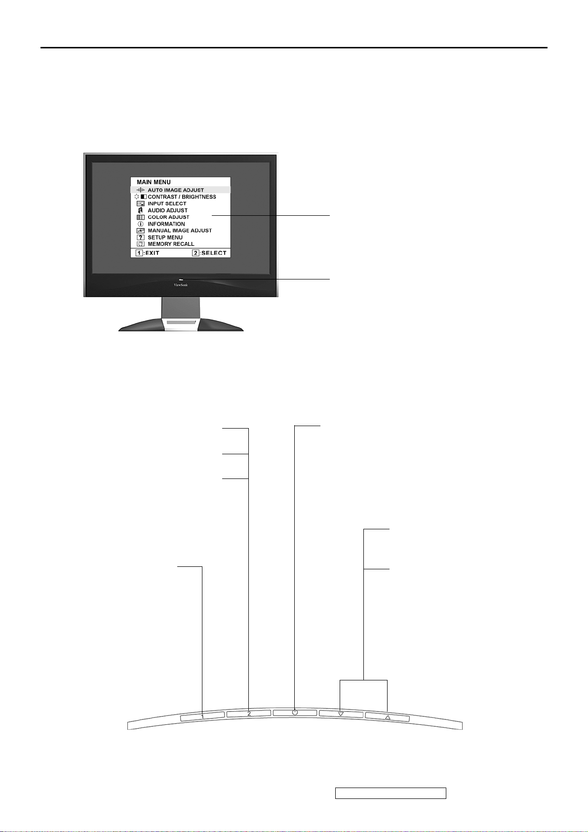
3. Front Panel Function Control Description
Adjusting the Screen Image
Main Menu
with OSD controls
Front Control Panel
shown below in detail
Displays the control screen for
the highlighted control.
Also toggles between two
controls on some screens.
Also a shortcut to Auto Image
Adjust.
Displays the Main
Menu or exits the
control screen and
saves adjustments.
Standby Power On/Off
Power light
Blue = ON
Orange = Power Saving
Scrolls through menu
options and adjusts the
displayed control.
Also a shortcut to display
the Contrast adjustment
control screen.
ViewSonic Corporation Confidential - Do Not Copy VX1945wm-3
14
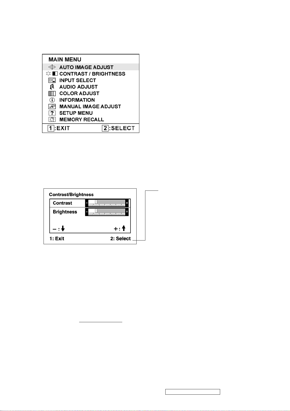
Do the following to adjust the display setting:
1. To display the Main Menu, press button [1].
NOTE: All OSD menus and adjustment screens disappear automatically after about 15
seconds. This is adjustable through the OSD timeout setting in the setup menu.
2. To select a control to adjust, pressSorTto scroll up or down in the Main Menu.
3. After the desired control is selected, press button [2]. A control screen like the one shown
below appears.
The command line at the bottom of the
control screen tells what to do next from
this screen. You can toggle between control
screens, adjust the selected option, or exit
the screen.
4. To adjust the setting, press the up S or down T buttons.
5. To save the adjustments and exit the menu, press button [1] twice.
The following tips may help you optimize your display:
• Adjust the computer's graphics card so that it outputs a 1440 x 900 @ 60Hz video signal to
the LCD display. (Look for instructions on “changing the refresh rate” in the graphics card's
user guide.)
• If necessary, make small adjustments using H. POSITION and V. POSITION until the
screen image is completely visible. (The black border around the edge of the screen should
barely touch the illuminated “active area” of the LCD display.)
ViewSonic Corporation Confidential - Do Not Copy VX1945wm-3
15

Main Menu Controls
Adjust the menu items shown below by using the up S and down T buttons.
Control Explanation
Auto Image Adjust sizes and centers the screen image automatically.
Contrast adjusts the difference between the image background (black level)
and the foreground (white level).
Brightness adjusts background black level of the screen image.
Input Select toggles between inputs if you have more than one computer
connected to the VX1945wm.
Audio Adjust
Vol ume increases the volume, decreases the volume, and mutes the audio.
Mute temporarily silences audio output.
Color Adjust provides several color adjustment modes, including preset color
temperatures and a User Color mode which allows independent adjustment of
red (R), green (G), and blue (B). The factory setting for this product is 6500K
(6500 Kelvin).
ViewSonic Corporation Confidential - Do Not Copy VX1945wm-3
16
Control Explanation
sRGB-This is quickly becoming the industry standard for color management,
with support being included in many of the latest applications. Enabling this
setting allows the LCD display to more accurately display colors the way they
were originally intended. Enabling the sRGB setting will cause the Contrast and
Brightness adjustments to be disabled.
9300K-Adds blue to the screen image for cooler white (used in most office
settings with fluorescent lighting).
7500K - Adds blue to the screen image for cooler white (used in most office
settings with fluorescent lighting).
6500K-Adds red to the screen image for warmer white and richer red.
5400K-Adds green to the screen image for a darker color.
User Color Individual adjustments for red (R), green (G), and blue (B).
1. To select color (R, G or B) press button [2].
2. To adjust selected color, pressSandT.
Important: If you select RECALL from the Main Menu when the product is
set to a Preset Timing Mode, colors return to the 6500K factory preset.
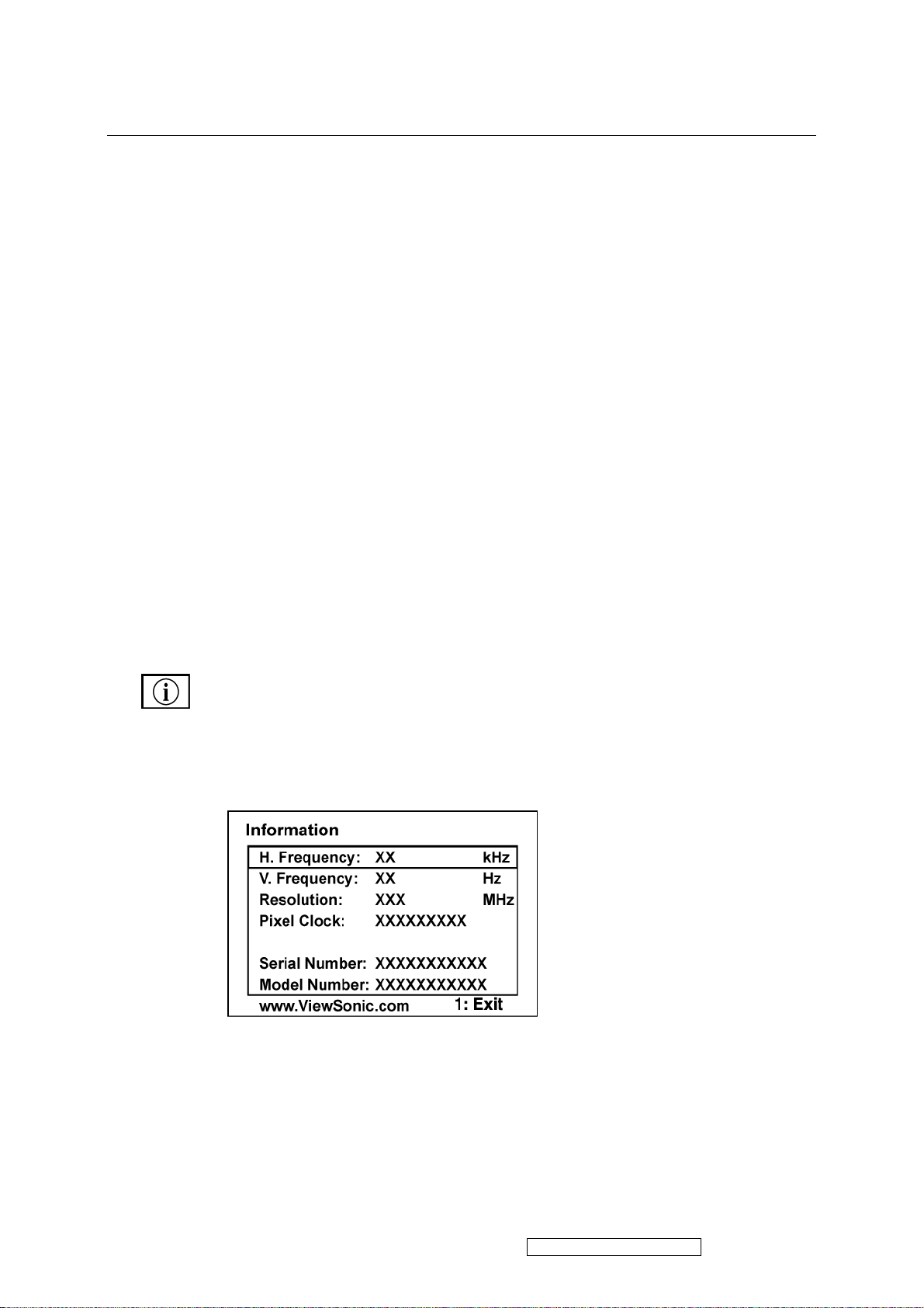
Information displays the timing mode (video signal input) coming from the
graphics card in the computer, the LCD model number, the serial number, and
the ViewSonic® website URL. See your graphics card’s user guide for
instructions on changing the resolution and refresh rate (vertical frequency).
NOTE: VESA 1440 x 900 @ 60Hz (recommended) means that the resolution is
1440 x 900 and the refresh rate is 60 Hertz.
ViewSonic Corporation Confidential - Do Not Copy VX1945wm-3
17
Control Explanation
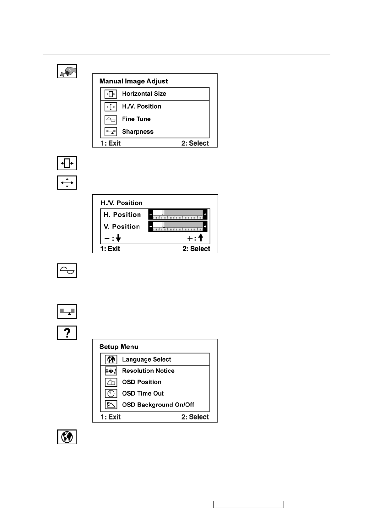
Manual Image Adjust Sub-menu
H. Size (Horizontal Size) adjusts the width of the screen image.
H./V. Position (Horizontal/Vertical Position) moves the screen image left or
right and up or down.
Fine Tune sharpens the focus by aligning text and/or graphics with pixel
boundaries.
NOTE: Try Auto Image Adjust first.
Sharpness adjusts the clarity and focus of the screen image.
Setup Menu displays the menu shown below:
Language Select allows the user to choose the language used in the menus and
control screens.
ViewSonic Corporation Confidential - Do Not Copy VX1945wm-3
18
Control Explanation
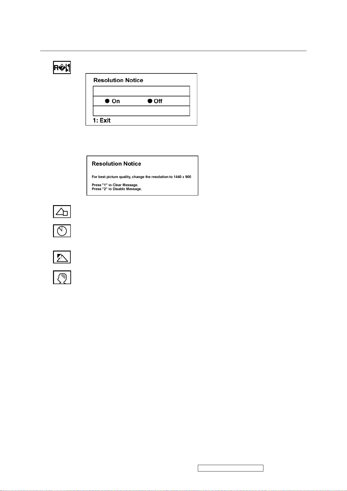
Resolution Notice allows the user to enable or disable this notice.
If you enable the Resolution Notice shown above and your computer is set at a
resolution other than 1440 x 900, the following screen appears.
OSD Position allows the user to move the OSD menus and control screens.
OSD Timeout sets the length of time the OSD screen is displayed. For example,
with a “30 second” setting, if a control is not pushed within 30 seconds, the
display screen disappears.
OSD Background allows the user to turn the OSD background On or Off.
Memory Recall returns the adjustments back to factory settings if the display is
operating in a factory Preset Timing Mode listed in the Specifications of this
manual.
ViewSonic Corporation Confidential - Do Not Copy VX1945wm-3
19

ViewDockTM Key Features
Features
The VX ViewDock comes with the following advanced features:
• 4-port USB 2.0 hub (USB 1.1 compatible)
• 8-in-1 card reader (SD, MMC, MS, MS Pro, CF I & II, MD, SMC)
• 3-watt subwoofer support
• iPod docking & charging
• Headphone jack and built-in microphone
System requirements
For optimal use with the ViewDock, the computer should have the following minimum system
requirements:
Hardware requirements
• Pentium 200 CPU or higher
• CD-ROM for driver installation
• USB2.0/1.1 interface
• 32 MB memory
Software Requirements
• Microsoft Windows 98SE/2000/ME/XP
• MAC OS 8.5+ or higher version.
ViewSonic Corporation Confidential - Do Not Copy VX1945wm-3
20
 Loading...