

Page 1

Service Manual
ViewSonic VX1935wm-1
Model No. VS11307
19” Color TFT LCD Display
(VX1935wm-1_SM Rev. 1a Sep. 2006)
ViewSonic 381 Brea Canyon Road, Walnut, California 91789 USA - (800) 888-8583
Page 2
Copyright
Copyright © 2006 by ViewSonic Corporation. All rights reserved. No part of this publication
may be reproduced, transmitted, transcribed, stored in a retrieval system, or translated into any
language or computer language, in any form or by any means, electronic, mechanical, magnetic,
optical, chemical, manual or otherwise, without the prior written permission of ViewSonic
Corporation.
Disclaimer
ViewSonic makes no representations or warranties, either expressed or implied, with respect to
the contents hereof and specifically disclaims any warranty of merchantability or fitness for any
particular purpose. Further, ViewSonic reserves the right to revise this publication and to make
changes from time to time in the contents hereof without obligation of ViewSonic to notify any
person of such revision or changes.
Trademarks
Optiquest is a registered trademark of ViewSonic Corporation.
ViewSonic is a registered trademark of ViewSonic Corporation.
All other trademarks used within this document are the property of their respective owners.
Revision History
Revision SM Editing Date ECR Number Description of Changes Editor
1a 9/18/2006 Initial Release Jamie Chang
ViewSonic Corporation Confidential - Do Not Copy VX1935wm-1
i
Page 3

TABLE OF CONTENTS
1. Precautions and Safety Notices 1
2. Specification 4
3. Front Panel Function Control Description 8
4. Circuit Description 13
5. Adjustment Procedure 14
6. Troubleshooting Flow Chart 32
7. Recommended Spare Parts List 34
8. Exploded Diagram and Exploded Parts List 37
9. Block Diagram 40
10. Schematic Diagrams 41
11. PCB Layout Diagrams 51
ViewSonic Corporation Confidential - Do Not Copy VX1935wm-1
ii
Page 4

1. Precautions and Safety Notices
1. Appropriate Operation
(1) Turn off the product before cleaning.
(2) Use only a dry soft cloth when cleaning the LCD panel surface.
(3) Use a soft cloth soaked with mild detergent to clean the display housing.
(4) Disconnect the power plug from AC outlet if the product is not used for a long period of
time.
(5) If smoke, abnormal noise, or strange odor is present, immediately switch the LCD
display off.
(6) Do not touch the LCD panel surface with sharp or hard objects.
(7) Do not place heavy objects on the LCD display, video cable, or power cord.
(8) Do not use abrasive cleaners, waxes or solvents for your cleaning.
(9) Do not operate the product under the following conditions:
- Extremely hot, cold or humid environment.
- Areas susceptible to excessive dust and dirt.
- Near any appliance generating a strong magnetic field.
- Place in direct sunlight.
2. Caution
No modification of any circuit should be attempted. Service work should only be
performed after you are thoroughly familiar with all of the following safety checks and
servicing guidelines.
3. Safety Check
Care should be taken while servicing this LCD display. Because of the high voltage
used in the inverter circuit, the voltage is exposed in such areas as the associated
transformer circuits.
4. Power Supply Requirements
The external AC power operating range shall be from 90 to 264Vac
ViewSonic Corporation Confidential - Do Not Copy VX1935wm-1
1
Page 5

5. LCD Module Handling Precautions
5.1. Handling Precautions
(1) Since front polarizer is easily damaged, pay attention not to scratch it.
(2) Be sure to turn off power supply when inserting or disconnecting from input
connector.
(3) Wipe off water drop immediately. Long contact with water may cause discoloration or
spots.
(4) When the panel surface is soiled, wipe it with absorbent cotton or other soft cloth.
(5) Since the panel is made of glass, it may break or crack if dropped or bumped on hard
surface.
(6) Since CMOS LSI is used in this module, take care of static electricity and insure
human earth when handling.
(7) Do not open nor modify the Module Assembly.
(8) Do not press the reflector sheet at the back of the module to any directions.
(9) In case if a Module has to be put back into the packing container slot after once it was
taken out from the container, do not press the center of the CCFL Reflector edge.
Instead, press at the far ends of the CFL Reflector edge softly. Otherwise the TFT
Module may be damaged.
(10) At the insertion or removal of the Signal Interface Connector, be sure not to rotate nor
tilt the Interface Connector of the TFT Module.
(11) After installation of the TFT Module into an enclosure (LCD monitor housing, for
example),
do not twist nor bend the TFT Module even momentary. At designing the enclosure, it
should be taken into consideration that no bending/twisting forces are applied to the
TFT Module from outside. Otherwise the TFT Module may be damaged.
(12) Cold cathode fluorescent lamp in LCD contains a small amount of mercury. Please
follow local ordinances or regulations for disposal.
(13) Small amount of materials having no flammability grade is used in the LCD module.
The LCD module should be supplied by power complied with requirements of Limited
Power Source, or be applied exemption.
(14) The LCD module is designed so that the CFL in it is supplied by Limited Current
Circuit.
Do not connect the CFL in Hazardous Voltage Circuit.
ViewSonic Corporation Confidential - Do Not Copy VX1935wm-1
2
Page 6
5.2 Handling and Placing Methods
Correct Methods: Incorrect Methods:
1.Take out the monitor with cushions 1.Taking out the monitor by grasping the LCD
panel. That may cause ”Mura”
2.Only touch the metal frame of the LCD panel
or the front cover of the monitor. Do not
touch the surface of the polarizer.
2.Surface of the LCD panel is pressed by
fingers and that may cause ”Mura”.
3.Place the monitor on a clean and soft foam
pad.
3.Placing the monitor on foreign objects. That
could scratch the surface of the panel or
cause “Mura”.
ViewSonic Corporation Confidential - Do Not Copy VX1935wm-1
3
Page 7
2. Specification
FEATURES VX1935
Size 19 " wide
TFTLCD PANEL
1st
HSD
HSD190MGW1-A
Input Signal
Sync
Compatibility
Compatibility
Power Voltage AC 100-240V, 50/60Hz Yes
Consumption
Audio 1.5W / THD 0.5% (Max) Yes
Ergonomics
Luminance (Typ)
Contrast Ratio (Typ) *1 700:1
Colors 16.2 M (6 bits + 2 bits FRC)
Response Time *1 5 ms (on/off)
Viewing Angle (H/V) 150 ° / 135 °@ CR>10
Recommend resolution 1440x900@60Hz
Analog Yes (75ohms, 0.7/1.0 Vp-p)
Digital Yes
Separate Sync Yes
Composite Sync No
Sync on Green No
PC Yes
Power Mac Yes
TV Box (NextVision 6) Yes
On Mode(Max) ≦ 36 W (Energy Star Ver4.0 Tier2)/ Power
Off Mode (Max) ≦1 W
Tilt ( 20 ° - -5 °) Yes
Swivel No
Pivot No
Height Adjust No
300 cd/㎡
OSD Control [ 1 ] [ 2 ] [ ][▼] [▲] Yes
Dimension
Weight
Operating
Condition
Storage Condition
Regulation
Physical (W x H x D) 450 x 434 x 210mm
Package (W x H x D) 545*515*162mm
Physical (Net Weight) 5.6 Kg / 12.3 lbs
Package (Gross Weight) 6.6 Kg / 14.5 lbs
Temperature (℉/℃) 32℉-104℉ / 0℃-40℃
Humidity (%) 20 % - 80 %
Temperature (℉/℃) -4℉-140℉ / -20℃-60℃
Humidity (%) 10% - 90 %
CB ; MPR II ; UL ; CUL ; FCC-B (ICES) ; TUV-S IRAM ; NOM ;
Energy Star ; CE ; NEMKO ERGO ; GOST-R ; HYGIENIC (20
copies) ; SASO ; BSMI ; C-TICK ; PSB ; CCC ; WEEE ; ROHS
z Audio Interface (Speaker Specification)
Line input signal 1.0 Vrms
Line input impedance > 10 kOhm
Maximum Amp power output (Watt)
Speaker Power rating(Ω/Watt) 8Ω/ 1.5 W (MAX)
THD ≦ 8% (Maxmum output @ 1KHZ)
Signal to Noise Ratio 50 dB
Frequency response 500 Hz – 20 Khz
SPL.
Line input connection
1.2 W (RL=8Ω)
80 ± 3 dB / 10.W‧0.5m
3.5 mm stereo jacks
ViewSonic Corporation Confidential - Do Not Copy VX1935wm-1
4
Page 8
Vibration
There should be no audible vibration
resonance at volume=100%(input
signal within 1.0 Vrms)
Screen image
Connector PC99 requirement Audio in
There should be no affect on the screen
image stability under any conditions
Lime Green pantone # 577C
Cable type / length 3.5mm stereo cable / 1.8m length
SPEAKERS STAY ON WHEN THE
REST OF THE MONITOR IS IN
POWER SAVING
Audio DPMS
NOTE: THERE IS NO GUARANTEE <1
W AT POWER CONSUMPTION IN
ACTIVE OFF MODE, WHEN THE
AUDIO CABLE IS CONNECTED
z Panel Characteristics:
1st Source Panel
Model number HSD HSD190SGW1-A
Type TN TYPE WITH RSDS INTERFACE
Active Size 19” WIDE ; 408.24 (H) x 255.15 (V)
Pixel Arrangement RGB VERTICAL STRIPE
Pixel Pitch 0.2835(H) X 0.2835(H) MM
Glass Treatment ANTI GLARE (HARD COATING 3H)
# of Backlights 4 CCFL ; TOP & BOTTOM EDGE SIDE
Backlight Life 40,000 HOURS (MIN)
Luminance (5-point) –
Condition:
CT = 6500K, Contrast = Max,
Brightness = Max, Inverter
Current=6.5mA
Brightness Uniformity ≧70% ENTIRE AREA (MIN)
Contrast Ratio *1 700:1 (TYP), 450:1 (MIN)
Color Depth 16.2 MILLION COLORS (6 BITS + 2 BITS
Viewing Angle (Horizontal) @ CR>10
Viewing Angle (Vertical) @ CR>10
Response Time *1
10%-90% @ Ta=25°C
Panel Defects Please see Panel Quality Specifications.
*1 Test conditions: Inverter Current=6.5mA, Color Temp.=User Mode, OSD: Brightness=100%, Contrast=100%
300 CD/M2 (TYP)
240 CD/M2 (MIN AFTER 30 MINUTE WARM
UP)
FRC)
Typical: 150º
Minimum: 130º
@ CR>5
Typical: 170º
Minimum: 150º
Typical: 140º
MINIMUM: 120º
@ CR>5
Typical: 160º
Minimum: 140º
Typical = 5ms (Tr =
1.5 ms,Tf =3.5 ms)
Maxmum = 10ms (Tr =3 ms,Tf =7 ms)
ViewSonic Corporation Confidential - Do Not Copy VX1935wm-1
5
Page 9
ELECTRICAL REQUIREMENT
k
y
e
Horizontal / Vertical Frequency
Horizontal Frequency 24 – 80 kHz
Vertical Refresh Rate 50 – 75 Hz.
Maximum Pixel Clock 135 MHz
Sync Polarity Independent of sync polarity.
Timing Table
Mod
1 640×350 @70Hz VGA31.46970.087 25.175 P N 800 96 48 640 16 449 2 60 350 37
2 640×350 @85Hz VGA37.86185.080 31.500 P N 832 64 96 640 32 445 3 60 350 32
3 640×400 @60Hz VGA31.46959.940 25.175 N P 800 96 48 640 16 525 2 73 400 50
4 640×400 @70Hz VGA31.46970.087 25.175 N P 800 96 48 640 16 449 2 35 400 12
5 640×400 @85Hz VGA37.86185.080 31.500 N P 832 64 96 640 32 445 3 41 400 1
6 640×480 @50Hz VGA24.68849.637 19.750 N P 800 64 80 640 16 497 4 10 480 3
7 640×480 @60Hz VGA31.46959.940 25.175 N N 800 96 48 640 16 526 2 33 480 11
8
9 640×480 @72Hz VGA37.86172.809 31.500 N N 832 40 128 640 24 520 3 28 480 9
10 640×480 @75Hz VGA37.50075.000 31.500 N N 840 64 120 640 16 500 3 16 480 1
11 640×480 @85Hz VGA43.26985.008 36.000 N N 832 56 80 640 56 509 3 25 480 1
12 720×400 @70Hz VGA31.46970.087 28.322 N P 900 108 45 720 27 449 2 35 400 12
13 720×400 @85Hz VGA37.92785.039 35.500 N P 936 72 108 720 36 446 3 42 400 1
fH fV Dot clock
Mod
e
14 720x480@60Hz 31.469 59.940 27.000 N N 858 62 76 720 0 525 6 39 480 0
15 720x576 @50Hz 31.250 50.000 27.000 N N 864 64 12 720 68 625 5 5 576 39
16
17
18
19
20
21
22 1024×768 @50Hz XGA 39.643 49.980 52.000 N P 1312 104 144 1024 40 793 4 18 768 3
23 1024×768 @60Hz XGA 48.363 60.004 65.000 N N 1344 136 160 1024 24 806 6 29 768 3
24 1024×768 @70Hz XGA 56.476 70.069 75.000 N N 1328 136 144 1024 24 806 6 29 768 3
25 1024×768 @75Hz XGA 60.023 75.029 78.750 P P 1312 96 176 1024 16 800 3 28 768 1
26
27 1024×768 @85Hz XGA 68.677 84.997 94.500 P P 1376 96 208 1024 48 808 3 36 768 1
28
29 1152×870 @75Hz MAC 68.681 75.062 100.000 N N 1456 128 144 1152 32 915 3 39 870 3 SOG can support
30 1280×768@50Hz 39.593 49.929 65.250 N P 1648 128 184 1280 56 793 7 15 768 3
31 1280×768 @60Hz 47.396 59.995 68.250 P N 1440 32 80 1280 48 790 7 12 768 3
32 1280×768 @60Hz 47.776 59.870 79.500 N P 1664 128 192 1280 64 798 7 20 768 3
33 1280×768 @75Hz 60.289 74.893 102.250 N P 1696 128 208 1280 80 805 7 27 768 3
34 1280×768 @85Hz 68.633 84.837 117.500 N P 1712 136 216 1280 80 809 7 31 768 3
35 1280×960 @50Hz 49.405 49.853 83.000 N P 1680 128 200 1280 72 991 4 3 960 3
36 1280×960 @60Hz 60.000 60.000 108.000 P P 1800 112 312 1280 96 1000 3 36 960 1
Resolution (KHz) (Hz) (MHz) H V A B C D E O P Q R S
40×480 @67Hz MAC35.00066.667 30.240 N N 864 64 96 640 64 525 3 39 480 3 SOG can support
Resolution (KHz) (Hz) (MHz) H V A B C D E O P Q R S
800×600 @56Hz
SVGA
800×600 @60Hz
SVGA
800×600 @72Hz
SVGA
800×600 @75Hz
SVGA
800×600 @85Hz
SVGA
832×624 @74.6Hz
MAC
1024×768 @75Hz
MAC
1152×864 @75Hz
SXGA
fH fV Dot cloc
35.156 56.250 36.000 P P 1024 72 128 800 24 625 2 22 600 1
37.879 60.317 40.000 P P 1056 128 88 800 40 628 4 23 600 1
48.077 72.188 50.000 P P 1040 120 64 800 56 666 6 23 600 37
46.875 75.000 49.500 P P 1056 80 160 800 16 625 3 21 600 1
53.674 85.061 56.250 P P 1048 64 152 800 32 631 3 27 600 1
49.725 74.500 57.283 N N 1152 64 224 832 32 667 3 39 624 1 SOG can support
60.150 74.720 80.000 N N 1330 96 168 1024 42 805 3 31 768 3
67.500 75.000 108.000 P P 1600 128 256 1152 64 900 3 32 864 1
ync polarit
Sync
polarity
Horizontal (dot) Vertical (line)
Horizontal (dot) Vertical (line)
備註
Performance no
guarantee
Performance no
guarantee
Performance no
guarantee
Performance no
guarantee
Performance no
guarantee
Performance no
guarantee
備註
Performance no
guarantee
Performance no
guarantee
Performance no
guarantee
Performance no
guarantee
Performance no
guarantee
Performance no
guarantee
Performance no
guarantee
Performance no
guarantee
ViewSonic Corporation Confidential - Do Not Copy VX1935wm-1
6
Page 10
Dot
fH fV
Mod
e
37 1280×960 @75Hz 74.592 74.443 128.895 P P 1728 136 224 1280 88 1002 3 36 960 3
38 1280×1024 @50Hz SXGA 52.679 49.838 80.500 N P 1680 128 200 1280 72 1057 7 23 1024 3
39 1280×1024 @60Hz SXGA 63.981 60.020 108.000 P P 1688 112 248 1280 48 1066 3 38 1024 1
41 1280×1024 @72Hz SXGA 76.020 71.448 130.223 P P 1712 133 248 1280 51 1064 2 38 1024 0
42 1280×1024 @75Hz SXGA 79.976 75.025 135.000 P P 1688 144 248 1280 16 1066 3 38 1024 1
43 1360×768 @60Hz WXGA 47.712 60.015 85.500 P P 1792 112 256 1360 64 795 6 18 768 3
44
45
46
47
48
49
50
Resolution (KHz) (Hz) (MHz) H V A B C D E O P Q R S
1400×1050 @50Hz WXGA
+
1400×1050 @60Hz WXGA
+
1400×1050 @60Hz WXGA
+
1400×1050 @75Hz WXGA
+
1440×900 @60Hz WXGA
+
1440×900 @60Hz WXGA
+
1440×900 @75Hz WXGA
+
54.113 49.965 100.000 N P 1848 144 224 1400 80 1083 4 26 1050 3
64.744 59.948 101.000 P N 1560 32 80 1400 48 1080 4 23 1050 3
65.317 59.978 121.750 N P 1864 144 232 1400 88 1089 4 32 1050 3
82.278 74.867 156.000 N P 1896 144 248 1400 104 1099 4 42 1050 3
55.469 59.901 88.750 P N 1600 32 80 1440 48 926 6 17 900 3
55.935 59.887 106.500 N P 1904 152 232 1440 80 934 6 25 900 3
70.635 74.984 136.750 N P 1936 152 248 1440 96 942 6 33 900 3
Sync
clock
polarity Horizontal (dot) Vertical (line)
備註
Performance no
guarantee
Performance no
guarantee
*1. Tolerance ± 2kHz.≧
*2. Any timing not in the list, it should display as normal or show on “OUT OF RANGE” OSD message without
blanking.
*3. The image quality of 85Hz mode might be worse than 75Hz. (Display quality is not guaranteed because the LCD
panel supports upto 75Hz)
Primary Presets
1440x900 @ 60Hz
User Presets
Number of User Presets (recognized timings) Available: 10 presets total in FIFO configuration
Changing Modes
● Maximum Mode Change Blank Time for image stability : 3 seconds (Max), excluding “Auto
Image Adjust” time
● Under DOS mode (640 x 350, 720 x 400 & 640 x 400), it should recall factory setting when
execute “Auto Image Adjust”
● The monitor needs to do “Auto Adjust” the first time when a new mode is detected(See
section “0-Touch™ Function Actions”)
ViewSonic Corporation Confidential - Do Not Copy VX1935wm-1
7
Page 11
3. Front Panel Function Control Description
3.1 Short Cuts Function from the button(s)
[1] Main Menu
[2] Input toggle (Analog or Digital)
[▼] or [▲] To immediately activate Brightness /Contrast menu.
Hot Keys for Function Controls
[▼]+ [▲] Recall Contrast or Brightness while in the Contrast or
Brightness adjustment, or recall both of Contrast and
Brightness when the OSD is not on.
[1] + [2] Toggle 720x400 and 640x400 mode when input 720x400
or 640x400 mode
[1] + [▼] + [▲]
(hold for 3 sec)
[1] + [▼]
(hold for 10 sec)
[1] + [▲]
(hold for 10 sec)
[2] + [ ]
with signal (hold for 3 sec)
Remark : All the short cuts function are only available while OSD off
White Balance. White Balance should set the screen on
the pure black and white pattern with 640*480@60Hz
resolution.
Power Lock (Unlock). User won’t be able to turn off the
monitor.
OSD Lock (Unlock). It will lock all functions.
Factory Mode (Press [ ] exit factory mode. )
Inter Factory Mode adjust white balance and setting Burn
in Mode (On or Off) .
3.2 Front Panel Hardware Controls
Power Switch (Front Head) Power Control, soft Power Switch.
Power LED (Front Head) Blue – ON
Front Panel Controls (Head)
[ 1 ] [ 2 ] [ ] [▼] [▲]
Reaction Time OSD must fully appear within 0.5s after
Orange – Active Off
Dark = Soft Power Switch OFF
[ 1 ] Button 1
[ 2 ] Button 2
[ ] Power
[▼] Down Arrow Button
[▲] Up Arrow Button
Note: Power Button, Button 1 and Button 2
must be one-shot logic operation. (i.e. there
should be no cycling)
pushing Button 1
ViewSonic Corporation Confidential - Do Not Copy VX1935wm-1
8
Page 12
3.3 OSD Menu Controls
Select the menu items shown below by using the up [▲] and down [▼] buttons.
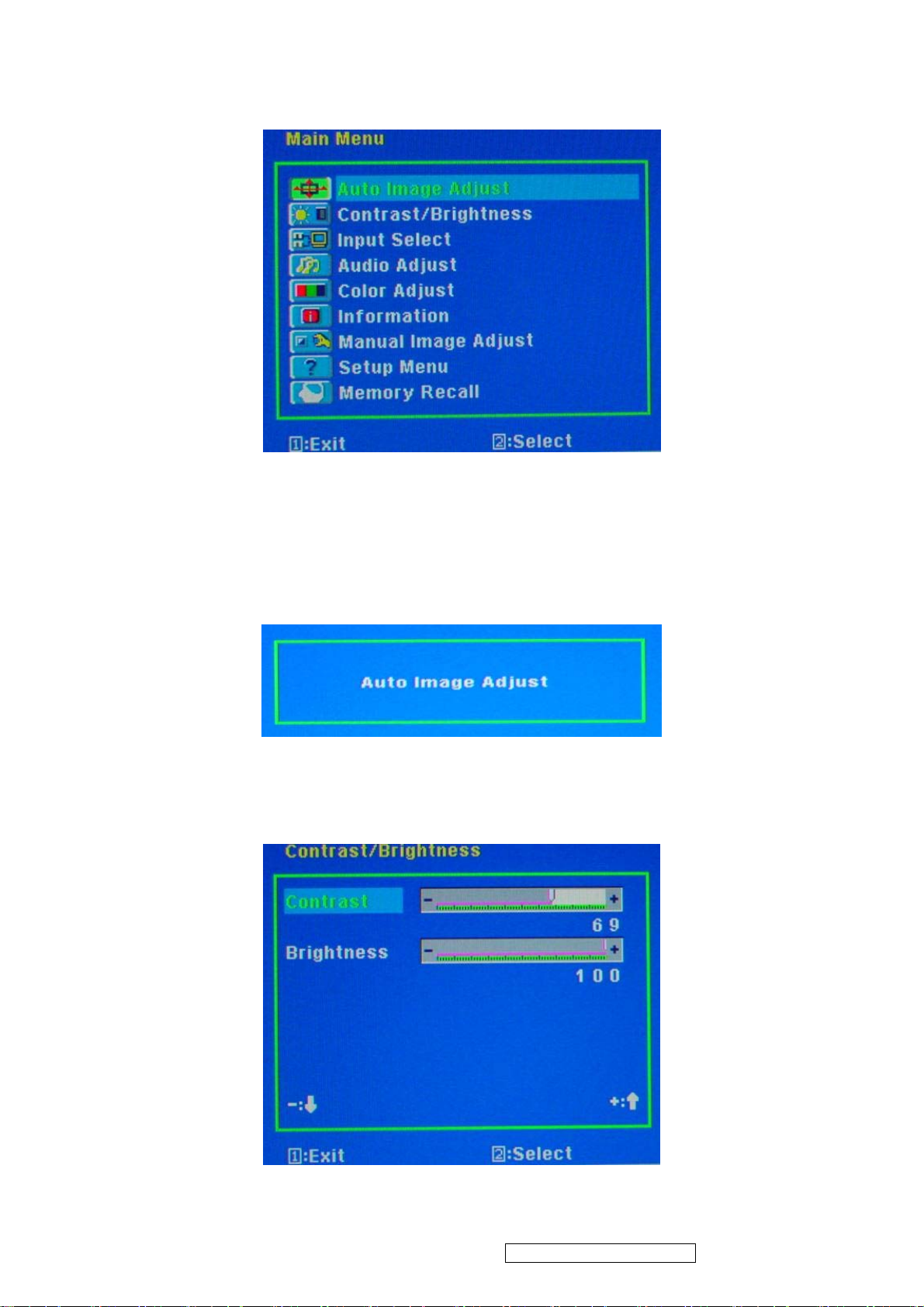
z Main Menu :
z Auto Image Adjust :
To automatically adjust H./ V. Position, Phase adjust and Clock adjust.
REMARK: There may need to select “Fine Tune” function on “Manual Image Adjust” to
optimized Performance for various VGA tolerance.
z Contrast / Brightness :
To adjust the Contrast of the video and the backlight currency.
ViewSonic Corporation Confidential - Do Not Copy VX1935wm-1
9
Page 13
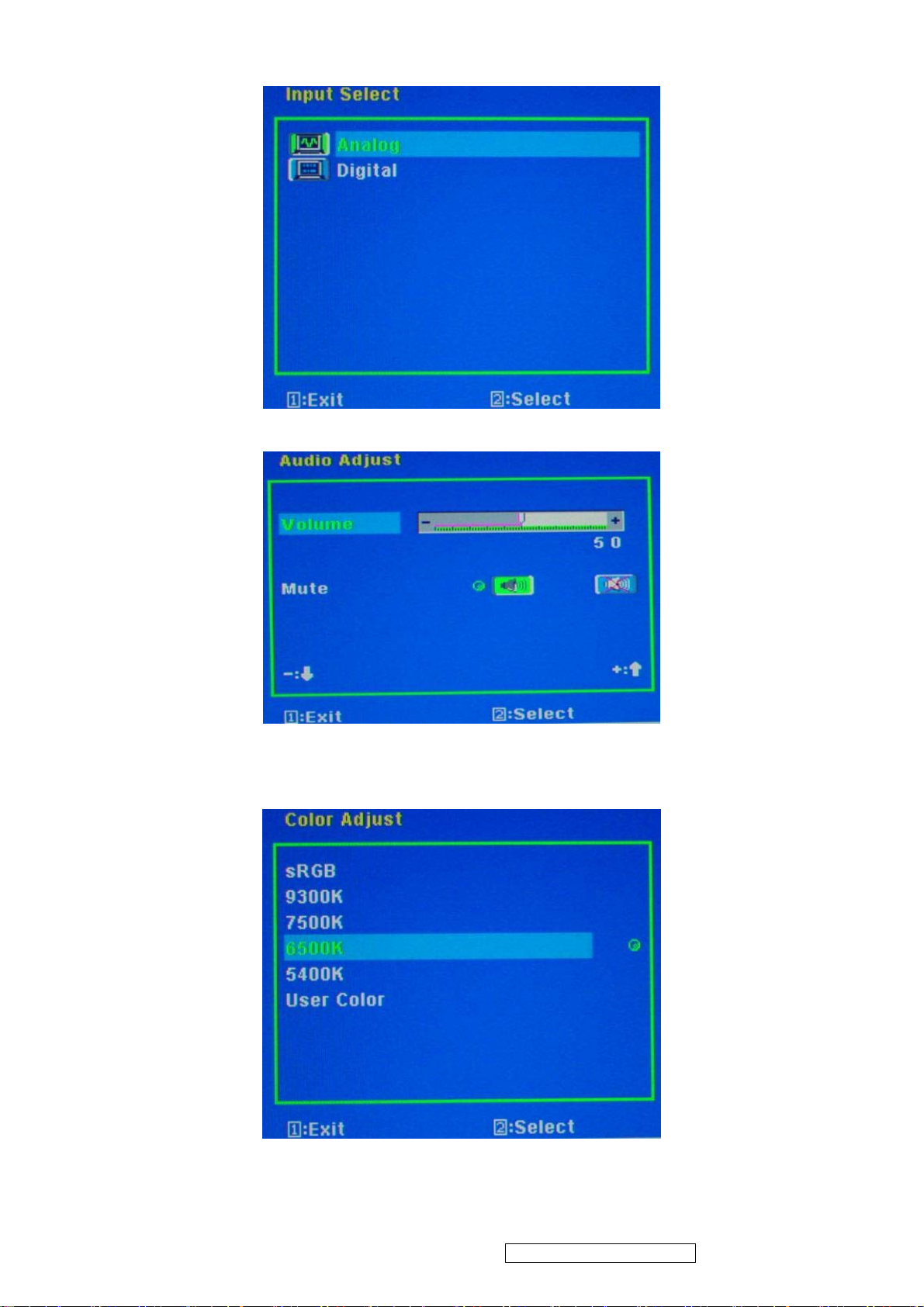
z Input Select :
To select the signal sources of the Analog or Digital.
z Audio Adjust :
To adjust the audio volume and mute.
z Color Adjust :
To select the color temperature sRGB, 9300°K, 7500°K ,6500°K, 5400°K or user color.
ViewSonic Corporation Confidential - Do Not Copy VX1935wm-1
10
Page 14
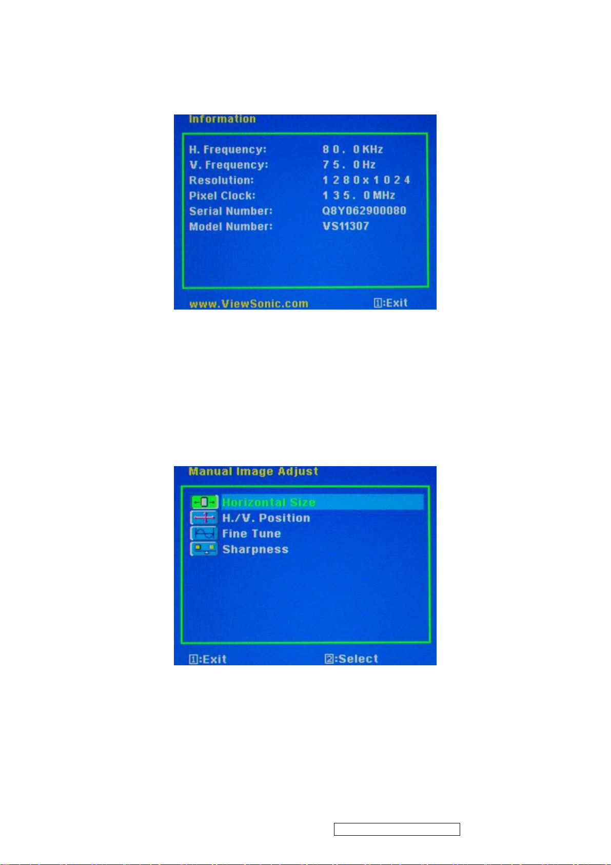
z Information:
To display the data about Horizontal / Vertical frequency, Pixel clock, Resolution ,
Model number and Serial No. of the monitor.
z Image Adjust:
Horizontal Size: To adjust the horizontal pixel clock of the video.
H./V. Position: To adjust the horizontal and vertical position of the video.
Fine Tune: To adjust the delay time of data and clock.
Sharpness: To select the picture sharpness of display.
ViewSonic Corporation Confidential - Do Not Copy VX1935wm-1
11
Page 15
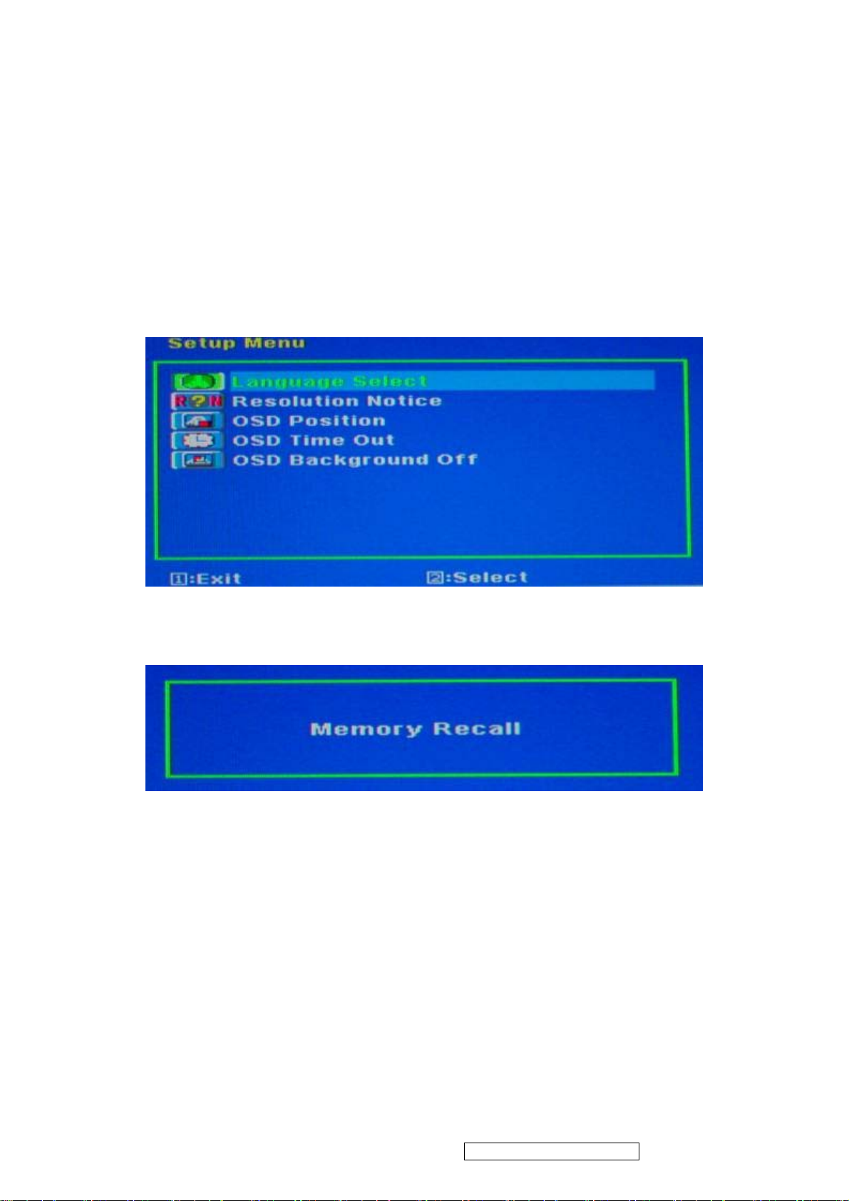
z Setup Menu::
Language Select: To select one of eight languages.(English, French, German, Italian,
Spanish, Finnish, Japanese, Traditional Chinese, and Simplified
Chinese)
Resolution Notice: Enable (on) : OSD will notify the best picture quality resolution change
the resolution to 1440 x 900
OSD Position: To set OSD position.
OSD Timeout: To set the displaying time of OSD.
OSD Background :To select video background brightness.
z Memory Recall:
Restore default settings of Clock, H./V. Position, Phase, Contrast, Brightness, Color
temperature, OSD position, OSD timeout and Sharpness, Volume.
ViewSonic Corporation Confidential - Do Not Copy VX1935wm-1
12
Page 16

4. Circuit Description
1. Power supply (DC/DC Converter)
This brick convert is the 110-220AC input voltage to 12V AND 5V output for inverter,
audio, panel and system controller use.
It consists of a PWM IC (CM0565R, U101)
2. Scaling controller
The ADC is to convert RGB analog signal to digital signal that scaling chip can
acknowledge.
The HSYNC input receives a logic signal and provides the frequency reference for
pixel clock generation.
The scaling IC is to converts the input signal ranging from VGA to WXGA into WXGA
resolution that panel can acknowledge.
GENERAL DESCRIPTION
The TSUM17AK is a high performance, and fully integrated graphics processing IC solution
for LCD monitors with resolutions up to WXGA. It is configured with an integrated triple-ADC/PLL,
a high quality scaling engine, an on-screen display controller, a built-in output clock generator,
and LVDS display interface. To further reduce system costs, the TSUM17AK also integrates
intelligent power management .
ViewSonic Corporation Confidential - Do Not Copy VX1935wm-1
13
Page 17
5. Adjustment Procedure
1. Function Test
1.1 Product
- 19” LCD Monitor
1.2 Test Equipment
- Color Video Signal & Pattern (or PC with WXGA resolution and a sound card)
1.3 Test Condition
Before function test and alignment, each LCD Monitor should be run-in and warmed
up for at least 30 minutes with the following conditions:
(a) In room temperature,
(b) With full-white screen, RGB, and Black
(c) With cycled display modes,
640*480 (H=43.27kHz, V=85Hz)
800*600 (H=53.7kHz, V=85Hz)
1024*768 (H=68.67kHz, V=85Hz)
1280*1024 (H=79.97kHz, V=75Hz)
1440*900 (H=70.63kHz, V=75Hz)
1.4 Test Display Modes & Pattern
1.4.1 Compatible Modes
Digital Analog
1. 640 x 480 @ 60Hz, 31.5kHz
2. 640 x 480 @ 67Hz, 35.0kHz
3. 640 x 480 @ 75Hz, 37.5kHz
4. 640 x 480 @ 72Hz, 37.9kHz
5. 640 x 480 @ 85Hz, 43.27kHz
6. 720 x 400 @ 70Hz, 31.5kHz
7. 800 x 600 @ 56Hz, 35.1kHz
8. 800 x 600 @ 60Hz, 37.9kHz
9. 800 x 600 @ 75Hz, 46.9kHz
10. 800 x 600 @ 72Hz, 48.1kHz
11. 800 x 600 @ 85Hz, 53.7kHz
12. 832 x 624 @ 75Hz, 49.7kHz
13. 1024 x 768 @ 60Hz, 48.4kHz
14. 1024 x 768 @ 70Hz, 56.5kHz
15. 1024 x 768 @ 72Hz, 58.1kHz
16. 1024 x 768 @ 75Hz, 60.0kHz
17. 1024 x 768 @ 85Hz, 68.67kHz
18. 1280 x 1024 @ 60Hz, 63.4kHz
19. 1280 x 1024 @ 75Hz, 79.97kHz
20. 1440 x 900 @ 75Hz, 70.63kHz
1.4.2 Function Test Display Pattern
1. 640 x 480 @ 60Hz, 31.5kHz
2. 640 x 480 @ 67Hz, 35.0kHz
3. 640 x 480 @ 75Hz, 37.5kHz
4. 640 x 480 @ 72Hz, 37.9kHz
5. 640 x 480 @ 85Hz, 43.27kHz
6. 720 x 400 @ 70Hz, 31.5kHz
7. 800 x 600 @ 56Hz, 35.1kHz
8. 800 x 600 @ 60Hz, 37.9kHz
9. 800 x 600 @ 75Hz, 46.9kHz
10. 800 x 600 @ 72Hz, 48.1kHz
11. 800 x 600 @ 85Hz, 53.7kHz
12. 832 x 624 @ 75Hz, 49.7kHz
13. 1024 x 768 @ 60Hz, 48.4kHz
14. 1024 x 768 @ 70Hz, 56.5kHz
15. 1024 x 768 @ 72Hz, 58.1kHz
16. 1024 x 768 @ 75Hz, 60.0kHz
17. 1024 x 768 @ 85Hz, 68.67kHz
18. 1280 x 1024 @ 60Hz, 63.4kHz
19. 1280 x 1024 @ 75Hz, 79.97kHz
20. 1440 x 900 @ 75Hz, 70.63kHz
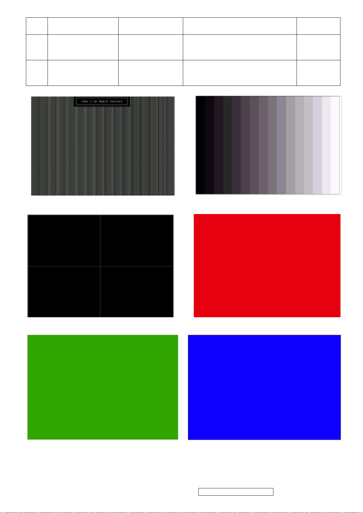
Item Test Content Pattern Specification Remark
1 Frequency &
Tracking
2 Contrast/Brightness 16 Gray Scale 16 gray levels should be
3 Boundary Horizontal &
4 RGB Color
Performance
Fine Line Moire Eliminate visual wavy
noise.
distinguishable.
Horizontal and Vertical position
Vertical
Thickness
RGB Color
Intensities
of video should be adjustable to
be within the screen frame.
Contrast of each R, G, B, color
should be normal.
Figure 1
Figure 2
Figure 3
Figure 4, 5,
6
ViewSonic Corporation Confidential - Do Not Copy VX1935wm-1
14
Page 18
5 Screen Uniformity
& Flicker
6 Dead Pixel/Line White Screen &
7 White Balance White & Black
Full White Should be compliant with the
Dark Screen
Pattern
spec.
The numbers of dead pixels
should be compliant with the
spec.
The screen must have the pure
white and black pattern, no other
color.
Figure 7
Figure 7, 8
Figure 9
Fine Line Morie Pattern (Figure1) Gray Scale Pattern (Figure2)
Horizontal & Vertical Thickness Pattern
(Figure 3)
R. Color Pattern (Figure 4)
G. Color Pattern (Figure5) B. Color Pattern (Figure 6)
ViewSonic Corporation Confidential - Do Not Copy VX1935wm-1
15
Page 19
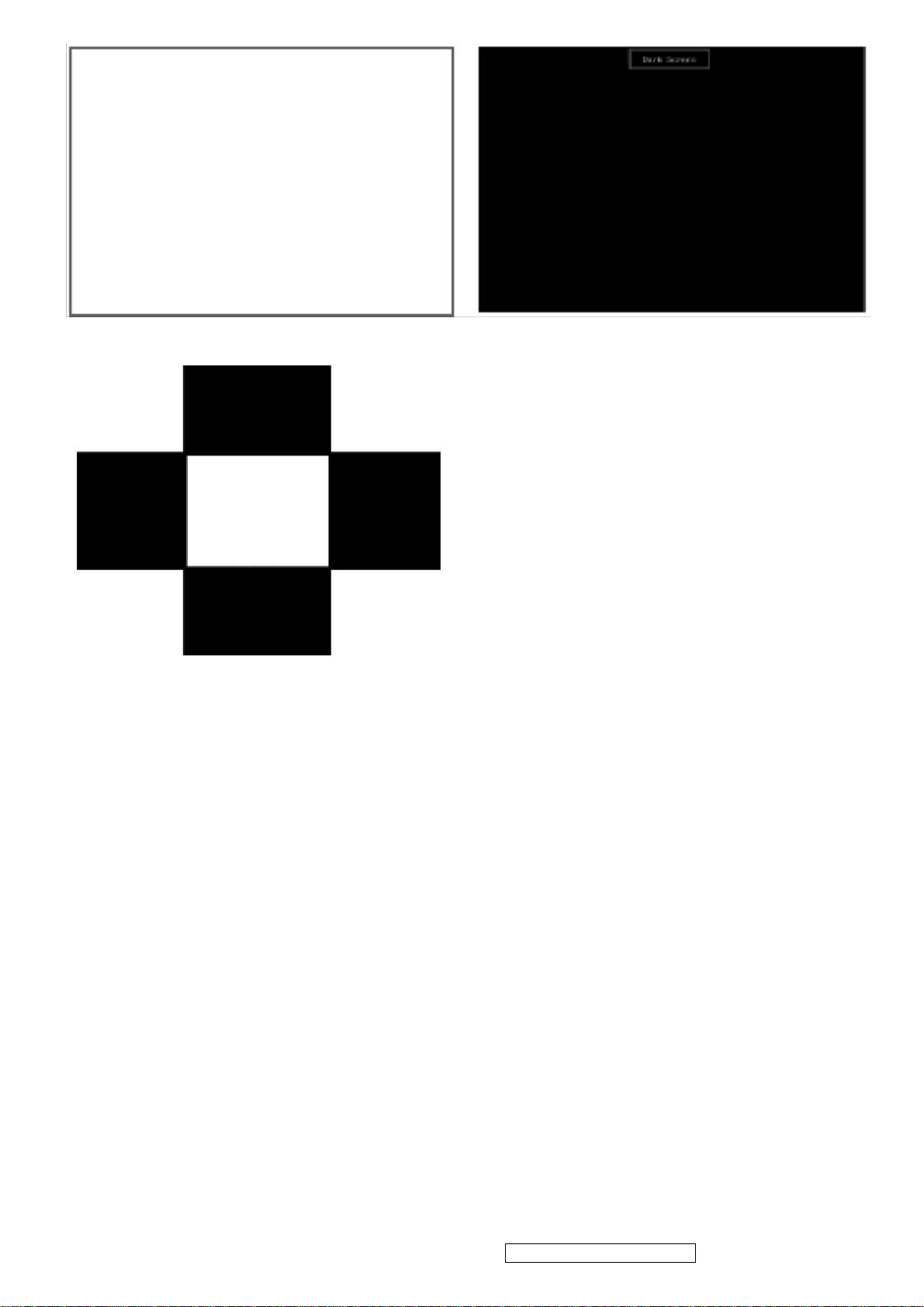
Full White Patter (Figure 7) Dark Screen Pattern (Figure 8)
Black-White Pattern (Figure 9)
1.5 Function Test and Alignment Procedure
1.5.1 Memory Recall
You should do “Memory Recall” first. This action will allow you to erase all
end-user’s settings and restore the factory defaults.
1.5.2 Auto Image Adjust
Please select and enter “Auto Image Adjust” function on Main Menu to see if it is
workable.
The “Auto Image Adjust” function is aimed to offer a better screen quality by
built-in ASIC. For optimum screen quality, the user has to adjust each function
manually.
1.5.3 Firmware
Test Pattern: Burn In Mode (Refer to Chapter 3-1. Hot Keys for Function Controls)
- Make sure the F/W is the latest version.
1.5.4 DDC
Test Pattern: EDID program
- Make sure it can pass test program.
1.5.5 Fine Tune and Sharpness
ViewSonic Corporation Confidential - Do Not Copy VX1935wm-1
16
Page 20

Test Signal: 1440x900@60Hz
Test Pattern: Line Moire Pattern
- Check and see if the image has noise and focus performs well. Eliminate visual line
bar.
- If not, readjust by the following steps:
(a) Select and enter “Fine Tune” function on “Manual Image Adjust” to adjust the
image
to eliminate visual wavy noise.
(b) Then, select and enter “Sharpness” function to adjust the clarity and focus of the
screen image.
1.5.6 Boundary
Test Signal: 1440x900@60Hz
Test Pattern: Horizontal & Vertical Line Thickness Pattern
- Check and see if the image boundary is within the screen frame.
- If not, readjust by the following steps:
(a) Select and enter “Manual Image Adjust” function on OSD Main Menu.
(b) Then, select and enter “Horizontal Size” or “Horizontal/Vertical Position”
function to adjust the video boundary to be full scanned and within screen frame.
1.5.7 White Balance
Test Signal: 1440x900@60Hz
Test Pattern: White and Black Pattern
1.5.8 R, G, B, Colors Contrast
Test Signal: 1440x900@60Hz
Test Pattern: R, G, B, Color Intensities Pattern and 16 Gray Scale Pattern
- Check and see if each color is normal and distinguishable.
- If not, please return the unit to repair area.
1.5.9 Screen Uniformity and Flicker
Test Signal: 1440x900@60Hz
Test Pattern: Full White Pattern
- Check and see if it is in normal condition.
1.5.10 Dead Pixel and Line
Test Signal: 1440x900@60Hz
Test Pattern: Dark and White Screen Pattern
- Check and see if there are dead pixels on LCD panel with shadow gauge and filter
film.
- The total numbers and distance of dead pixels should be compliant with the spec.
1.5.11 Mura
Test Pattern: White, RGB, Black, & Grey
Test Tool: 8% ND Filter
- Check if the Mura can pass 8% ND Filter.
1.5.12 Audio
Test Signal: Voice signal (optional, depend on model)
Test Pattern: liberty
- Make sure there is audio output.
- Make sure that audio function (volume≦80%) is working without noise and
resonance.
- Make sure that the sound of right and left speakers are in balance.
ViewSonic Corporation Confidential - Do Not Copy VX1935wm-1
17
Page 21
1.5.13 Check for Secondary Display Modes
Test Signal:
Analog / Digital:
640*350@70Hz 640*480@60HZ / 75HZ 720*400@70Hz
800*600@60HZ / 75HZ 832*624@75Hz 1024*768@60HZ / 75HZ
1280*1024@60 / 75Hz
- Normally when the primary mode 1440x900@60Hz is well adjusted and compliant
with the specification, the secondary display modes will be great possible to be
compliant with the spec. But we still have to check with the general test pattern to
make sure every secondary is compliant with the specification.
1.5.14 Memory Recall
After final QC step, we have to erase all saved changes again and restore the
factory defaults. You should do “Memory Recall” again.
1.5.15 Power Off Monitor
Turn off the monitor by pressing “Power” button.
2. Firmware Upgrade Procedure
When you receive the returned monitor, please check whether the firmware version is the
latest.
If not, please do the following procedures to upgrade it to the latest version.
2.1 Equipment Needed
- VX1935WM Monitor
- Fixture for Firmware Upgrade
- VGA Cable
- PC (Personal Computer)
- ISP Tool
- Firmware Upgrade Program
- One additional monitor for checking the program execution
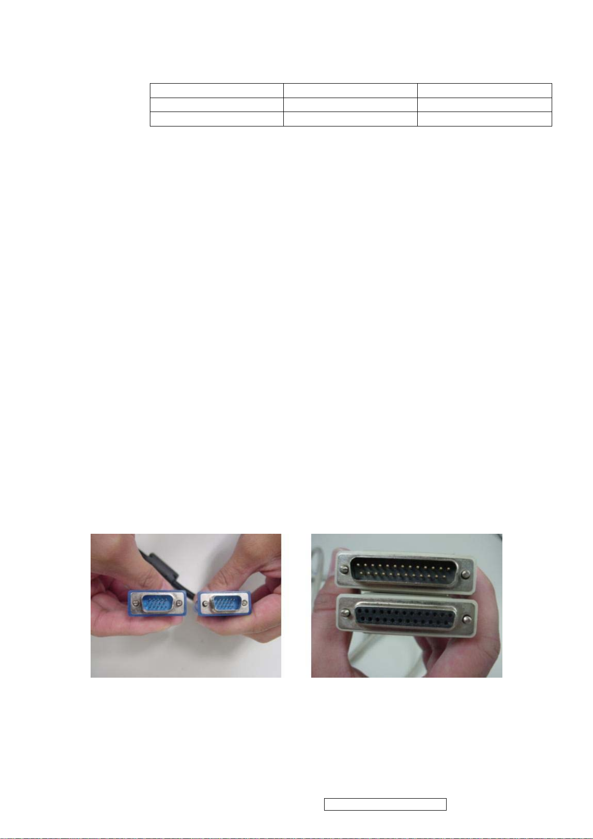
z ISP tool instruction
15 pin D-Sub LPT cable
ViewSonic Corporation Confidential - Do Not Copy VX1935wm-1
18
Page 22

ISP tool Use 12V adapter
ISP connect method
z ISP Download program procedure
¾ Hardware Connect status:
ViewSonic Corporation Confidential - Do Not Copy VX1935wm-1
19
Page 23

¾ Version update
1. Check : Monitor model
2. Check : Firmware version
Factory Mode :
a. Hold on [2] + [ ] with signal (hold for 3 seconds) into the factory mode.
b. Press [ ] key exit factory mode.
3. Update final firmware version
Example : ( VX1935WM follow the same setting procedure )
1. Check : Monitor model : HC154
2. Check : Firmware version : HC154_AL_150MX17A01R30.2 (ps)
3. Update final firmware version : HC154_AL_150MX17A01R30.3
(ps) HC154_AL_150MX17A01R30.2
AL : Analog / LVDS
DL : Analog + Digital / LVDS
AR : Analog /RSDS
DR : Analog + Digital / RSDS
Panel type : 150MX17A01
Firmware version : R30.2
¾ Change Panel (Version update)
1. Check : Monitor model
2. Check : Firmware version
ViewSonic Corporation Confidential - Do Not Copy VX1935wm-1
20
Page 24

Factory Mode :
a. Hold on [2] + [ ] with signal (hold for 3 seconds) into the factory mode.
b. Press [ ] key exit factory mode.
3. Check : Panel type.
4. Change Panel.
5. Update final firmware version.
6. Update EDID code.
Example : ( VX1935WM follow the same setting procedure )
1. Check : Monitor model : HC154
2. Check : Firmware version : HC154_AL_150MX17A00R30.2 (ps.1)
3. Check : Panel type : HSD150MX17A00.
4. Change Panel. (ps.2)
(ps.1) HC154_AL_150MX17A00R30.2
AL : Analog / LVDS
DL : Analog + Digital / LVDS
AR : Analog /RSDS
DR : Analog + Digital / RSDS
Panel type : 150MX17A01
Firmware version : R30.2
(ps.2) If change panel : (Form HSD150MX17A00 change to HSD150MX17A01)
Panel type : 150MX17A00 => 150MX17A01
Firmware change : HC154_AL_150MX17A00R30.2 =>
HC154_AL_150MX17A01R30.2
5. Update final firmware version : HC154_AL_150MX17A01R30.3
6. Update EDID code : HC154_150MX17A01_EDID_A.txt
ViewSonic Corporation Confidential - Do Not Copy VX1935wm-1
21
Page 25

¾ Change Scaler Board (Version update)
1. Check : Monitor model
2. Check : Firmware version
Factory Mode :
a. Hold on [2] + [ ] with signal (hold for 3 seconds) into the factory mode.
b. Press [ ] key exit factory mode.
3. Change scaler board.
4. Update final firmware version.
5. Update EDID code.
Example : ( VX1935WM follow the same setting procedure )
1. Check : Monitor model : HC154
2. Check : Firmware version : HC154_AL_150MX17A01R30.2 (ps)
(ps) HC154_AL_150MX17A01R30.2
AL : Analog / LVDS
DL : Analog + Digital / LVDS
AR : Analog /RSDS
DR : Analog + Digital / RSDS
Panel type : 150MX17A01
Firmware version : R30.2
3. Change scaler board.
4. Update final firmware version : HC154_AL_150MX17A01R30.3
5. Update EDID code : HC154_150MX17A01_EDID_A.txt
ViewSonic Corporation Confidential - Do Not Copy VX1935wm-1
22
Page 26

¾ Mstar scaler ISP function
1. Enforce Mstar ISP_Tool program.
2. After Enforcing Mstar ISP_Tool Program, open Utility Window.
3. Enforce Mstar ISP Utility Window's Connect function, and Device Type's Dialog
window will be opened ,then press "Sure " on Dialog window.
4. Enforce Mstar ISP Utility window 之 Read function.
ViewSonic Corporation Confidential - Do Not Copy VX1935wm-1
23
Page 27

5. Enforce Mstar ISP Utility window's "Read" , and choose the path and the file of Binary
code.
6. Choose the path and file of Binary code ,and Program Bin Ready Dialog window will
be opened, then press "Sure" on Dialog window.
7. Enforce Mstar ISP Auto function of Utility window.
ViewSonic Corporation Confidential - Do Not Copy VX1935wm-1
24
Page 28

8. Enforce Mstar ISP Utility window "Run"and write in the data .
9. After writing in the data , Enforce Dis Connect function of Mstar ISP Utility window and
the burn in procedure will be completed.
ViewSonic Corporation Confidential - Do Not Copy VX1935wm-1
25
Page 29

¾ DDC Key In Procedure
Note:
1. Every time after replacing the main board, you have to do the DDC key in.
2. If you find the DDC does not conform to the monitor, you have to do the DDC key in.
Equipment Needed
- VX1935 Series Monitor
- DDC Card
- PC
- RS232 cable
- VGA Cable or DVI Cable
DDC Card (D8330)
RS-232 Cable VGA Cable
Step 1 : Select VA903b in Working Model column to show EDID data on left
ViewSonic Corporation Confidential - Do Not Copy VX1935wm-1
26
Page 30

Step 2 : Modify the column of Week of Manufacture and Year of Manufacture and ID serial
Number then press “2B” button for changing serial number data.
Step 3 : You will see the result as follows.
ViewSonic Corporation Confidential - Do Not Copy VX1935wm-1
27
Page 31

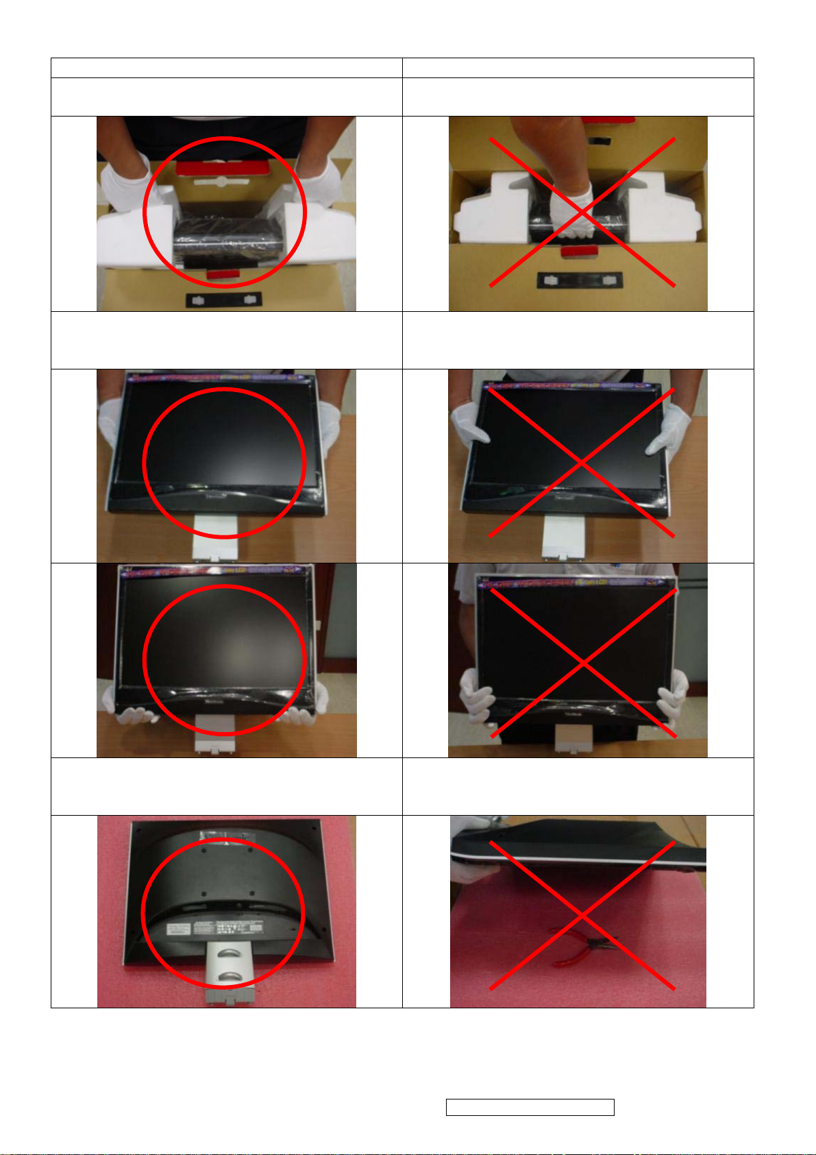
¾ Packing For Shipping And Disassembly Procedure
Packing For Shipping
1. Packing Procedure
1.1 Put the monitor in the PE bag and seal the bag with tape. (Figure 1 ~ 2)
1.2 Put the cushions on the monitor. (Figure 3) 1.3 Put the Cables in the PE bag. (Figure 4)
(Figure 1) (Figure 2)
Audio cable
D-Sub cable DVI cable Power code
(Figure 3) (Figure 4)
1.4 Place the monitor into the carton and then put all the accessories into the carton. At last,
close the carton and seal it with tape. (Figure 5 ~ 6)
Base short side turn upward
Panel side forward
(Figure 5) (Figure 6)
User’s manual / Warranty card / CD package
D-Sub/ DVI
cables
Power Code /
Audio Cable
ViewSonic Corporation Confidential - Do Not Copy VX1935wm-1
28
Page 32

Disassembly Procedure
1. Disassembly of Stand unit from Monitor
1.1 Detach Base Unit from the monitor.
1.2 Remove the ARM cover.
1.3 Unfasten six screws to remove the ARM.
2. Disassembly of Front Cover and Rear Cover
2.1 Unscrew ten screws to remove Rear Cover.
ViewSonic Corporation Confidential - Do Not Copy VX1935wm-1
29
Page 33

2.2 Unfasten four screws to remove Hinge folder bracket.
2.3 Unfasten six screws to remove the D-sub / DVI connector and Power socket.
2.4 Unfasten five screws and disconnect Inverter cables from panel to remove the shielding.
ViewSonic Corporation Confidential - Do Not Copy VX1935wm-1
30
Page 34

2.5 Unfasten four screws to remove the Keypad board.
2.6 Unfasten eight screws to remove Power Inverter board and D-sub/DVI connect board.
Power Inverter Board D-sub/DVI connect board Cables
2.7 Remove the Front Bezel.
ViewSonic Corporation Confidential - Do Not Copy VX1935wm-1
31
Page 35

6. Troubleshooting Flow Chart
Q1
NO POWER
Please check if power cable is
connected properly
YES
Change P/I/A board (ps)
Q2
NO
Please reconnect power
cable
NO DISPLAY
Please check if signal cable is
connected properly
YES
Change Panel
NO
Please reconnect signal
cable
Q3
Display panel have horizontal
line or vertical line
Please change panel
Q4
The backlight is OFF
1
Please check inverter
wire if properly connected
2
Please change panel or
P/I/A board (ps)
Q5
Display panel have block bar Please change panel
ViewSonic Corporation Confidential - Do Not Copy VX1935wm-1
32
Page 36

Q6
Display panel with missing
color
1
2
3
Q7
Audio output error
(ps) : P/I/A board Î Power/Inverter/Audio board
Please check signal cable if
connected properly and
check all pins are good
without bent
Please check if panel wire is
loose connection or not
Please change panel
Please change P/I/A
board (ps)
ViewSonic Corporation Confidential - Do Not Copy VX1935wm-1
33
Page 37

7. Recommended Spare Parts List
ViewSonic Model Number: VS11307
RECOMMENDED SPARE PARTS LIST (VX1935wm-1)
Serial No. Prefix: Q8Y Rev: 1a
Item ECR/ECN ViewSonic P/N Ref. P/N Location Universal number#
Accessories:
1
2
3
4
PC Board Assembly:
5
Cabinets:
6
7
8
9
10
11 Cables:
12 Audio Cable (SZE33261B) CB-00008003
Documentation:
13 Energy Star Label DC-00008001
14 Hi-Pot Pass Label DC-00008003
15
16
Electronic
17 Speaker 1.5W/8R RIGHT E-00008004
Components:
18 Speaker 1.5W/8R LEFT E-00008005
19
Miscellaneous:
20
Packing Material:
21
22
23
24
25
26
27
Plastics:
28
29
Remark 1: Above listed items are examples, supplier can expand the rows to add more necessary items.
Remark 2:
Description
Power Cord - 250V/10A 1.8M 3C BLK (China)
Power Cord - 125V/10A 1.8M 3C BLK (USA)
Power Cord - 250V/10A 1.8M 3C BLK (Europe)
SoftWare Packing assy (china)
Key Board (Lead Free)
Front Panel (B + Button)
Back Cover
Front Cover ( Silver)
Back Cover (Arm - Silver)
Cover (Silver)
Video Cable D/15P-15P(M)
Label (5ms sticker)
Label (Mylar 425*275*0.1)
LCD Module (HSD190SGW1-A)
Bird Logo Brand For Viewsonic M-00008001
PE BAG 225*400MM
PE BAG 500*650mm
Craft Box (TWN)
Craft Foam - Left
Generic Foam Set
Generic Box
Craft Foam - Right
Name plate Brand for Viewsonic PL-00008002
Pedestal Base (Black-C)
All revised RSPLs with newly added items or any change made should be highlighted and correlated with the ECN/ECR approved by ViewSonic
Corporation. This is to eliminate repeated cross checks of each item between this version and prior versions.
A-00008038
A-00008039
A-00008040
A-00008042
B-00008074
C-00008105
C-00008106
C-00008107
C-00008108
C-00008109
CB-00008001
DC-00008098
DC-00008099
E-00008073
P-00008004
P-00008005
P-00008085
P-00008086
P-00001347
P-00002515
P-00008088
PL-00008024
33-E3980005G000
33-E3980000G000
33-E3980003G000
72-01193502G000
70-VX193500G000
45-VX190117G350
45-VX190213G350
40-05010019G000
40-05010020G000
40-11010001G000
33-00090501G000
33-00070500G000
62-07000009G000
62-07000011G000
62-07000012G000
42-01260011G000
30-V9031R50G000
30-V9031R51G000
190SGW1-A00
42-04260007G000
61-03000003G000
61-03000007G000
60-01000032G000
61-01000029G000
30833
20653
61-01000034G000
42-04170008G000
40-06010019G000
ViewSonic Corporation Confidential - Do Not Copy VX1935wm-1
34
Page 38

BOM LIST ( VX1935wm-1 )
ViewSonic Model Number: VS11307
Serial No. Prefix: Q8Y
Rev: 1a
Item ViewSonic P/N Ref. P/N Description Location Universal number# Q'ty
1
2
3
4
5
6
7
8
9
10
11
12
13
14
15
16
17
18
19
20
21
22
23
24
25
26
27
28
29
30
31
32
33
34
35
36
37
38
39
40
41
42
43
44
45
46
47
48
49
50
51
52
53
54
55
56
A-00008042
N/A
B-00008074
N/A
N/A
N/A
DC-00008098
DC-00008003
DC-00008002
DC-00008001
N/A
N/A
N/A
N/A
N/A
N/A
N/A
N/A
N/A
N/A
N/A
P-00008005
P-00008004
P-00008088
P-00008086
P-00008085
C-00008106
C-00008105
N/A
N/A
N/A
N/A
N/A
N/A
M-00008001
PL-00008002
C-00008005
PL-00008001
DC-00008099
N/A
N/A
N/A
N/A
N/A
N/A
C-00008109
N/A
N/A
PL-00008024
C-00008108
C-00008107
N/A
N/A
N/A
N/A
N/A
72-01193502G000 VX1935 China Packing assy 1
72-01193501G000 VX1935 USA Packing assy 1
70-VX193500G000 VX1935 KEY BOARD ASS’Y (Lead Free) 1
62-07000017G000 Viewsonic POP sticker 1
62-07000015G000 ViewSonic Customer label 180*100mm (China) 1
62-07000014G000 Customer label (China) 1
62-07000012G000 5ms sticker 1
62-07000011G000 Hi-Pot Pass Label 1
62-07000010G000 QC-Pass Label (china) 1
62-07000009G000 Energy Star Label 1
62-06000006G000 Barcode label 35*4mm (China) 4
62-06000005G000 BARCODE LABEL 25*12MM 1
62-06000004G000 BARCODE LABEL 50*25MM 1
62-06000003G000 BARCODE LABEL 76.2*76.2MM 1
62-05000027G000 VX1935 ID LABEL TAIWAN 1
62-04000012G000 VX1935 CD User Guide 1
62-03000020G000 ViewSonic Warranty USA 1140*900 1
62-03000018G000 ViewSonic Warranty China 1
62-02000024G000 VX1935 Quick Start Taiwan 1
62-02000022G000 VX1935 Base Guide 1
61-03000011G000 PE bag 750*700mm (China) 1
61-03000007G000 PE BAG 500*650mm 1
61-03000003G000 U171 PE BAG 225*400MM 1
61-01000034G000 VX1935 END CAP-R EPS 1
61-01000029G000 VX1935 END CAP EPS 1
60-01000032G000 VX1935 Carton Viewsonic Taiwan 1
45-VX190213G350 VX1935wm Back Cover Sub-Assy 1
45-VX190117G350 VX1935wm Bezel-B + Button-B Sub-Assy 1
43-90000072G300 SCREW M4x10 PH SW+W NI ME 4
43-90000066G410 SCREW M3x8 PHW LW CR3/BL TAP 4
43-04030802G010 SCREW M3*8 FLAT NI TAP 4
43-02040602G000 Screw M4*6 Wafer Head Black-Ni Me 4
43-01030802G110 SCREW M3x8 PAN WASHER NI TAP 12
43-01030402G000 Screw M3*4 Pan Head Ni Me 2
42-04260007G000 Bird Logo Brand for Viewsonic AL+PC 1
42-04170008G000 Name plate Brand for Viewsonic AL 1
42-02110008G000 Back cover of ESD rubber-2 Black φ7*1.5 4
42-02110002G000 HU171 Rubber Foot Black 7
42-01260011G000 Mylar 425*275*0.1 for 19”W 1
41-07010015G000 VX1935wm Hinge SECC 1
41-03010061G000 VX1935wm speaker bracket SECC 4
41-03010052G000 VX1935M KEY LOCK BRACKET SECC 1
41-03010043G000 VX1935wm Hinge Sup. BKT SECC 1
41-03010042G000 VX1935wm Base BKT SECC 1
41-03010037G000 HX191_WALL MOUNT_BRACKET 2
40-11010001G000 VX1935wm Base_cover ABS-HB Silver 1
40-09010004G000 VX1935wm Cable Clipper DownABS-HB Silver 1
40-09010003G000 VX1935wm Cable Clipper Up ABS-HB Silver 1
40-06010019G000 VX1935wm Base ABS-HB Pantone Black-C 1
40-05010020G000 VX1935wm Arm_Back cover ABS-HB Silver 1
40-05010019G000 VX1935wm Arm_front cover ABS-HB Silver 1
40-04020010G000 VX1935wm Power LENS PC 1
40-03010031G000 VX1935wmButton 2-KeyABS-HB Pantone Black 1
40-03010030G000 VX1935wmButton 3-KeyABS-HB Pantone Black 1
40-02010024G000 VX1935wm Back cover ABS-HB Black 1
40-01010055G000 VX1935wm Bezel ABS-HB Pantone Black-C 1
ViewSonic Corporation Confidential - Do Not Copy VX1935wm-1
35
Page 39

Item ViewSonic P/N Ref. P/N Description Location Universal number# Q'ty
57
N/A
58
N/A
59
N/A
60
N/A
61
N/A
62
A-00008038
63
N/A
64
CB-00008001
65
A-00008003
66
N/A
67
CB-00008003
68
N/A
69
N/A
70
N/A
71
E-00008005
72
E-00008004
73
E-00008004
74
N/A
75
E-00008073
76
N/A
77
N/A
78
N/A
39-VX193500G000 VX1935 Key Board PCB Ver : 2.0 1
34-04170017G000 AL Foil W40*L200*T0.1mm 1
33-R3910506G000 CABLE STEREO PHONE(JHEN VEI) 1
33-R3910503G000 DVI CABLE 1800MM(JHEN VEI) 1
33-R3910501G000 CABLE SIGNAL D/15P-15P(M)1800MM-JHEN VEI 1
33-E3980005G000 PWR CORD CHN 250V/10A 1.8M 3C BLK"Linetek" 1
33-B1540503G000 DVI CABLE 1800MM WHITE SZE60288B(GLET) 1
33-00090501G000 CABLE SIGNAL D/15P-15P(M)1800MM 1
33-00080002G000 PWR CORD CHINA 250V/10A 1800MM LF 1
33-00080000G000 PWR CORD AMERICAN(UL/CSA) 125V/10A 1800m 1
33-00070500G000 CABLE STEREO PHONE SZE33261B 1
32-31012085G000 CONN W TO B 12P P*2.0 C1U2X-XX0VX(TACT) 1
32-31002083G000 CONN W TO B 2P P*2.0 C1U2X-XX0VX(TACT) 2
31-10400100G000 SW TACT 160GF DIP TSAC-2L 5
30-V9031R51G000 VA903 SPEAKER 1.5W/8R LEFT 1
30-V9031R50G000 VA903 SPEAKER 1.5W/8R RIGHT 1
30-V9031R50G000 VA903 SPEAKER 1.5W/8R RIGHT (China) 1
20-9MB04139G040 LED BLUE/Orange3P DIP (ENGYA) 1
190SGW1-A00 LIQUID CRYSTAL DEVICE HSD190SGW1-A 1
06-Y3352200G000 Bin Code VX1935_ DR_HSD190SGW1A00R30.2 1
04-1VX19GW1G100 EDID VX1935WM_190MGW1_EDID_D 1
04-1VX19GW1G000 EDID VX1935WM_190MGW1_EDID_A 1
ViewSonic Corporation Confidential - Do Not Copy VX1935wm-1
36
Page 40

8. Exploded Diagram and Exploded Parts List
ViewSonic Corporation Confidential - Do Not Copy VX1935wm-1
37
Page 41

Y
EXPLODED PARTS LIST (VX1935wm-1)
ViewSonic Model Number: VS11307
Rev: 1a
Serial No. Prefix: Q8
Item ViewSonic P/N Ref. P/N Description Q'ty
1 E-00008004 30-V9031R50G000 VA903 SPEAKER 1.5W/8R RIGHT 1
2 E-00008005 30-V9031R51G000 VA903 SPEAKER 1.5W/8R LEFT 1
3 N/A 40-09010003G000 VX1935wm Cable Clipper Up ABS-HB Silver 1
4 N/A 40-09010004G000 VX1935wm Cable Clipper Down ABS-HB Silver 1
5 N/A 41-03010042G000 VX1935wm Base BKT SECC 1
6 N/A 41-03010043G000 VX1935wm Hinge Sup. BKT SECC 1
7 N/A 41-07010015G000 VX1935wm Hinge SECC 1
8 C-00008005 42-02110008G000 Back cover of ESD rubber-2 Black φ7*1.5 4
9 B-00008074 70-VX193500G000 VX1935 KEY BOARD ASS’Y (Lead Free) 1
10 N/A 43-90000072G300 SCREW M4x10 PH SW+W NI ME 8
11 PL-00008001 42-02110002G000 HU171 Rubber Foot Black 7
12 N/A 40-01010055G000 VX1935wm Bezel ABS-HB Pantone Black-C 1
13 N/A 40-02010024G000 VX1935wm Back cover ABS-HB Black 1
14 N/A 40-03010030G000 VX1935wmButton 3-KeyABS-HB Pantone Black 1
15 N/A 40-03010031G000 VX1935wmButton 2-KeyABS-HB Pantone Black 1
16 N/A 40-04020010G000 VX1935wm Power LENS PC 1
17 C-00008107 40-05010019G000 VX1935wm Arm_front cover ABS-HB Silver 1
18 C-00008108 40-05010020G000 VX1935wm Arm_Back cover ABS-HB Silver 1
19 PL-00008024 40-06010019G000 VX1935wm Base ABS-HB Pantone Black-C 1
20 C-00008109 40-11010001G000 VX1935wm Base_cover ABS-HB Silver 1
21 N/A 41-03010037G000 HX191_WALL MOUNT_BRACKET 2
22 N/A 41-03010052G000 VX1935M KEY LOCK BRACKET SECC 1
23 PL-00008002 42-04170008G000 Name plate Brand for Viewsonic AL 1
24 N/A 43-01030802G000 SCREW M3x4 PAN,NI,ME 10
25 N/A 43-01040604G000 SCREW M4*6 PAN BZ ME 2
26 N/A 43-04030802G010 SCREW M3*8 FLAT NI TAP 4
27 N/A 43-90000066G410 SCREW M3x8 PHW LW CR3/BL TAP 4
28
E-00008073
190SGW1-A00 LIQUID CRYSTAL DEVICE HSD190SGW1-A 1
ViewSonic Corporation Confidential - Do Not Copy VX1935wm-1
38
Page 42

N
PACKING PART LIST (VX1935wm-1 )
ViewSonic Model Number: VS11307
Rev: 1a
Item ViewSonic P/N Ref. P/N Location Q'ty
1
2
3
4
5
6
7
8
9
10
11
12
13
N/A
N/A
N/A
N/A
A-00008004
P-00008005
P-00008004
P-00008086
P-00008088
DC-00008099
P-00008085
DC-00008098
/A
62-04000012G000 VX1935 CD User Guide
33-R3910501G000 CABLE SIGNAL D/15P-15P(M)1800MM-JHEN VEI
33-R3910503G000 DVI CABLE 1800MM(JHEN VEI)
33-R3910506G000 CABLE STEREO PHONE(JHEN VEI)
33-E3980011G000 PWR CORD TWN 125V/7A 1.8M 3C BLK "Linetek"
61-03000007G000 PE BAG 500*650mm
61-03000003G000 U171 PE BAG 225*400MM
61-01000029G000 VX1935 END CAP EPS
61-01000034G000 VX1935 END CAP-R EPS
42-01260011G000 Mylar 425*275*0.1(Protective Film) for 19”W
60-01000032G000 VX1935 Carton Viewsonic Taiwan
62-07000012G000 5ms sticker
62-06000003G000 BARCODE LABEL 76.2*76.2MM
ViewSonic Corporation Confidential - Do Not Copy VX1935wm-1
39
1
1
1
1
1
1
1
1
1
1
1
1
1
Page 43

9. Block Diagram
AC
INPUT
100V~240V
AUDIO
U501
TDA7496
SPEAKER
AUDIO
INPUT
SW Power
12V
5V
INVERTER
MP 1038EY
BL_EN
BL-BRIGHT
OSC 12M
Y1
VDD+5
PANEL
DISPLAY
SCALAR
U1
TSUM17AK
DC-DC
U401-1084-33PM
3.3V
DC-DC
U402-1084-18PM
1.8V
EEPROM
U3
24C16
H、SYNC
V、SYNC
H、V SYNC
VGA D-SUB
SCL、SDA
VGA 5V
R、G、
BINPUT
DDC
U501
24C02
Flash
U2
SST25VH010
DDC
U601
24C02
TMDS SYNC
SCL_DVI、SDA_DVI
DVI5V
ViewSonic Corporation Confidential - Do Not Copy VX1935wm-1
40
Page 44

10. Schematic Diagrams
Vin
GND
ON/OFF
IC_VCC
R12
DBRT
R40
C8
R1
C1
LV1
R41
R19
D1
C2
Q3
C4
IC_VCC
R9R3R10
R2
G
D S
Q1
C3
R4
R5
R7
C5
C6
C18
R6
R11
C21
R43
D15
14
13
12
11
10
9
8
7
6
5
4
3
2
1
R8
C7
U1
LOK
ENSYNC
ABRT
DBRT
BRS
BRC
LCC
LCS
FT
AG
COMP
LV
LI
SI
VCC
C24
OUTL
VCCL
OUTR
VCCR
BTL
PRL
UGL
LGL
PGL
BTR
PRR
UGR
LGR
PGR
C31
C35
LV1
CN1
CN1B
FB1
23
22
25
24
26
27
28
16
15
18
17
19
20
21
C25
C27
C26
C28
U2
3
S2
4
G2
1
S1
2
G1
U3
3
S2
4
G2
1
S1
2
G1
6
D2
5
D2
C36
8
D1
7
D1
6
D2
5
D2
C37
8
D1
7
D1
C29
C30
C19 C20
C32
T1
6.7
8
1
5
4
2.3
LV2
FB2
FB3
C33
LV3
FB4
C34
LV4
3
4
CN1A
1
2
CN2
CN2A
1
2
CN2B
3
4
LV2
LV3
LV4
D2
D3
D4
C14
C15
C16
C17
DS
R15
Q2
LI
D10 D12
R20R39R38
R16
R17
R34
FB1
C9
R23
R30
R31
D7
FB3
D13
JP10
2
1
4
3
IC_VCC
R21
LI LI
R26
R27
D5
D11
C11
R36
C22
R35
FB2
C10
R24
D8
R32
FB4
R33
G
R18
C23
D14
R25
R28
D6
R22
R29
C12
R37
ViewSonic Corporation
ViewSonic Corporation Confidential - Do Not Copy VX1935wm-1
41
Model
Title
INVERTER
Date Rev:
Page 45

CN100
L
FG
N
F101
1
4
CY102
LF101
CY101
2
VA101
3
TH101
R123
CX101
R122
R101
R102
CY104
R260A
LF102
2
3
1
BD101
2
4
R120R121
3
+
R112
ZD110
R113
R114
C114
1
4
1
C115
3
T101
R260B
11.12
D260
C260
C261
+
C264
R262
R263
INVERTER
+12V
ZD260
R264
ZD120
R124
C123
D240
U101
6
Ilimit
5
NC
4
FB
3
Vcc
+
C124
ZD121
Drain
GND
C120
1
2
PC201B
3 4
D110
D120
L120
7.8
R240A
R241
+
C244
+
C241
R230
12
R231
+
C232
IC230
A K
6
5
R240B
C240
9.10
R235
PC201A
C231
R
L240
R232
R234
R233
+
C242
+5.2V
+5.2V/3A
C243
RTN
ViewSonic Corporation Confidential - Do Not Copy VX1935wm-1
42
CY103
ViewSonic Corporation
Model
Title
Date Rev:
OPEN FRAME
Page 46

+12V
CN501
+
C501
C505
8
16
15
U501
FB501
R506
C502
+
+
C504
R507
R501
1
2
3
4
5
C509
C510
FB503
R502
R504
R505
C507
C508
11
12
4
9
6
INL
INR
VOLUME
STBY
MUTE
GND1GND2GND
NC
VS
VS
OUTL
OUTR
VAROUT_R
VAROUT_L
GND
GND18GND19GND
SVR
17
14
10
7
5
+
FB502
FB504
SPL
SPL
SPR
SPR
C512C511
C503
3
13
20
Volome
AUDIO_STBY
AUDIO_MUTE
Volume
R510
R511
AUDIO_STBY
AUDIO_MUTE
+5V
R503
Q501
R509R508
R512
C506
ViewSonic Corporation
Model
ViewSonic Corporation Confidential - Do Not Copy VX1935wm-1
43
Title
Date Rev:
AUDIO
Page 47

D1
LL4148WP
CHT2907
R1
100 1/16W
VCTRL
R2
51 1/16W
C1
+
Q1
B
C
E
D2
LL4148WP
4.7uF/35V
R3
2K 1/16W
1.8V
3.3V
VDVI
VMPLL
VPLL
AVDD
VDDP
VDDC
1.8V
3.3V
FB1
1 2
1000 OHM
FB2
1 2
600 OHM
+
10uF/16V
C2
10uF/16V
C3
VDDP
C4
0.1uF/16V
+
0.1uF/16V
C5
0.1uF/16V
C6
C7
0.1uF/16V
C8
0.1uF/16V
C9
0.1uF/16V
VDDC
C10
0.1uF/16V
C11
0.1uF/16V
C12
0.1uF/16V
3.3V
1 2
3.3V
1 2
FB4
600 OHM
FB3
600 OHM
C14
0.1uF/16V
VDVI
C13
0.1uF/16V
AVDD
C15
0.1uF/16V
3.3V
3.3V
FB6
1 2
600 OHM
0.1uF/16V
FB5
600 OHM
C16
0.1uF/16V
VPLL
C17
VMPLL
0.1uF/16V
C18
H11
H12
H13
DDC_SDA
DDC_SCL
NC/UDZS5.6B
Del R4 R5 CN1
06/01/06
C28
0.1uF/16V
5V
C27
+
10uF/16V
R13
10K 1/16W
R6 100 1/16W
R7 100 1/16W
D3
D4
NC/UDZS5.6B
1 2
1 2
3.3V
10K 1/16W
R14
NC
R15
8
7
3
4 5
WP
U2
VDD
HOLD#
WP#
VSS SDI
SST25VH010
C29
0.1uF
SDO
CE#
SCK
44
RIN0P
RIN0N
GIN0P
GIN0N
SOGIN0
BIN0P
BIN0N
HSYNC0
VSYNC0
DDCA_SDA
DDCA_SCL
RX2P
RX2N
RX1P
RX1N
RX0P
RX0N
RXCKP
RXCKN
DDCD_SDA
DDCD_SCL
REXT
REFP
REFM
SDO
SCZ
SCK
SDI
RST
XIN
XOUT
MODE[0]
MODE[1]
50
AVDD_DVI
AVDD_DVI
AVDD_MPLL
AVDD_MPLL
3.3V
R_IN+
R_IN-
G_IN+
G_IN-
SOGI
TP2
TP1
HSI
R9 NC
R8 NC
VSI
2
1
6
C30 22pF
C31 22pF
B_IN+
B_IN-
AVDD
Y1
14.318MHZ
3.3V
DVI_R+
DVI_RDVI_G+
DVI_GDVI_B+
DVI_B-
DVI_CLK+
DVI_CLK-
DVI_SDA
DVI_SCL
R16 NC
R17 NC
iris suggestion
2005/01/11
C19 0.047uF
C20 0.047uF
C21 0.047uF
C22 0.047uF
C23 0.047uF
C24 0.047uF
C25 0.047uF
R10 390 1%
R18
NC/ 1M 1/16W
C26
0.1uF
R19 10K 1/16W
R20 10K 1/16W
U1
59
58
56
55
57
54
53
63
64
65
66
39
40
42
43
45
46
48
49
36
37
51
62
61
70
71
72
73
19
32
33
102
104
67
14
52344
95
60
VDDP
VDDP
VDDP
AVDD_PLL
AVDD_ADC
TSUM17AK
RSDS/LVDS/TTL
GND
GND
GND
GND
GND
GND
41
47
3896116
13
12
68
97
103
115
117
VDDP
VDDP
VDDC
VDDC
VDDC
NC/LVACKP/NC
NC/LVACKM/NC
VDD_OTP
RA1P/LVA2P/RA2
RA1N/LVA2M/RA3
RA2P/LVA1P/RA4
RA2N/LVA1M/RA5
RA3P/LVA0P/RA6
RA3N/LVA0M/RA7
GA3P/LVA3P/GA6
GA3N/LVA3M/GA7
CLKAP/LVB3P/LHSYNC
CLKAN/LVB3M/LVSYNC
CLKBP/LVBCKP/LCK_ODD
CLKBN/LVBCKM/LDE
BB1P/LVB1P/BB2
BB1N/LVB1M/BB3
BB2P/LVB0P/BB4
BB2N/LVB0M/BB5
PWM2/GPIO_P24
GPIO_P27/PWM1
PWM1/GPIO_P25
GPIO_P17/SAR0
GPIO_P00/SAR1
GPIO_P01/SAR2
GPIO_P02/SAR3
PWM0/GPIO_P26
VCTRL
GA1P/NC/GA2
GA1N/NC/GA3
GA2P/NC/GA4
GA2N/NC/GA5
BA1P/NC/BA2
BA1N/NC/BA3
BA2P/NC/BA4
BA2N/NC/BA5
BA3P/NC/BA6
BA3N/NC/BA7
RB1P/NC/RB2
RB1N/NC/RB3
RB2P/NC/RB4
RB2N/NC/RB5
RB3P/NC/RB6
RB3N/NC/RB7
GB1P/NC/GB2
GB1N/NC/GB3
GB2P/NC/GB4
GB2N/NC/GB5
GB3P/NC/GB6
GB3N/NC/GB7
NC/LVB2P/NC
NC/LVB2M/NC
BB3P/NC/BB6
BB3N/NC/BB7
GPO0
GPO1
GPO2
GPO3
GPO4
GPO5
GPO6
GPIO_P22
GPIO_P23
GPIO_P03
GPIO_P16
GPIO_P15
GPIO_P16
GPIO_P06
GPIO_P07
GPIO_P13
GPIO_P14
DDCROM_SCL
DDCROM_SDA
ESP
OSP
11
107
108
109
110
111
112
113
114
98
99
100
101
105
106
89
90
91
92
93
94
9
10
15
16
17
18
2
3
5
6
7
8
118
119
120
121
122
123
124
125
126
127
128
1
80
81
88
87
86
85
84
83
82
75
74
26
35
69
78
79
20
21
22
23
24
25
27
28
29
30
31
77
76
VCTRL
RA0
RA1
RA2
RA3
RA4
RA5
GA0
GA1
GA2
GA3
GA4
GA5
BA0
BA1
BA2
BA3
BA4
BA5
RB0
RB1
RB2
RB3
RB4
RB5
GB0
GB1
GB2
GB3
GB4
GB5
CLKAP
CLKAN
CLKBP
CLKBN
BB0
BB1
BB2
BB3
BB4
BB5
ESP
OSP
R21 22 1/16W
R22 22 1/16W
R23 22 1/16W
R24 22 1/16W
R25 22 1/16W
WP
R26 100 1/16W
Modify 060424
RA[0..5]
GA[0..5]
BA[0..5]
RB[0..5]
GB[0..5]
CLKAP
CLKAN
CLKBP
CLKBN
BB[0..5]
TP4
TP3
R620 0 1/16W
R621 100 1/16W
R27 100 1/16W
R28 100 1/16W
R29 100 1/16W
3.3V
R62
NC/100 1/16W
R50 4.7K 1/16W
SCL
SDA
RB SWAP NP
有和
SWAP
的功能
POL
LP
POL
LP
STV1
CPV
OE
R618NC/4.7K 1/16W
R30 4.7K 1/16W
R31 4.7K 1/16W
R33 4.7K 1/16W
TP6
TP5
R51 4.7K 1/16W
R622 4.7K 1/16W
R52 100 1/16W
R53 100 1/16W
TP7
R32 4.7K 1/16W
C33 0.1uF/16V
iris suggestion
2005/01/11
R63 0 1/16W
U3
8
7
6
AT24C16N-10SC-2.7
VCC
WP
SCL
3.3V
R34 39K 1/16W
GNDSDA
R35 39K 1/16W
A0
A1
A2
R619 39K 1/16W
R36 4.7K 1/16W
1
2
3
45
LEDG
LEDB
STHB,F SWAP 10/06
R11 NC
R12 NC
R37 22 1/16W
R38 22 1/16W
R39 NC/22K 1/16W
5V
SW2_VOL-
DVI_DET
VGA_DET
PWR_EN
SW1_AUTO
SW5_MENU
SW4_VOL+
PWR
R40 10K 1/16W
R54 4.7K 1/16W
STH_B
STH_F
R41 10K 1/16W
5V
R56 4.7K 1/16W
R55 4.7K 1/16W
R57 15K 1/16W
STH_B
STH_F
C32
NC/0.1uF/16V
R42NC/10K 1/16W
L2
1
1
L8
80ohmL980ohm
H2
H8
1
L3
L11
L7
80ohm
80ohm
80ohm
H3
1
1
1
R44 10K 1/16W
LEDG
R45 10K 1/16W
LEDB
R58 NC
R59 4.7K 1/16W
1
L4
L6
L5
L1
80ohm
80ohm
80ohm
H1
H7
80ohm
80ohm
5V
R43
NC/4.7K 1/16W
BL_EN
BL_BRIGHT
TP12
DDC_WP
AMP_MUTE
AMP_STBY
Q2
NC/PMBS3904
TP9
TP8
TP10
TP11
L12
80ohm
80ohm
R46 47 1/16W
PMBS3906
R47 47 1/16W
PMBS3906
5V
R60 1K 1/16W
Q5
PMBS3904
1
L10
H5
1
H10
1
5V
Q3
R48 47 1/16W
5V
Q4
R49 47 1/16W
R61 220K 1/16W
H6
H9
C34
0.1uF/16V
1
H4
1
1
PWR_LEDG
PWR_LEDB
VOLUME
ViewSonic Corporation
ViewSonic Corporation Confidential - Do Not Copy VX1935wm-1
44
Model
Title
SCALER
Date Rev:
Page 48

VDD+5
R101
0 1/16W
C102
C101
10uF/16V
10uF/16V
R103
10.7K (0402) 1%
iris suggestion
2005/01/10
IN
LK.CD032.A01
L101
102K (0402) 1%
iris suggestion
2005/01/12
R104
VDDA(+13.4V)
D101
SSM5819SPT
1 2
D
Q101
G
AO3404L
S
iris suggestion
2005/01/11
C1040.1uF(0402)
iris suggestion
2005/01/10
C10510uF/16V
C10610uF/16V
1206
1206
R105
VDDA
0 1/16W
C10710uF/16V
1206
VDDA
iris suggestion
2005/01/10
VGL(-10V)
VGL
C109
VGL
470pF/50V
VGL
C108
0.1uF(0402)
NC
C103
C110
0.1uF/10V
R106 0
R102
NC (0402)
IN
200K(0402) 1%
24.9K(0402) 1%
REF
FBP
FBN
R107
FBN
R109
REF
C119
0.22uF/25V
U101
1
/RDY
2
3
4
5
6
7
8 9
TGND
FB
INTG
PGND
IN
SUPP
GND
DRVP
REF
SUPN
FBP
DRVN
FBN /SHDN
MAX1748
1
C111
10uF/16V
2
LX
D102
3
BAT54WSPT
16
15
14
13
12
11
10
IN
C112
0.1uF (0402)
C116
0.1uF/25V(0603)
C115
0.1uF(0402)
C113
0.1uF(0603)
C114 0.1uF(0402)
2
D103
BAT54WSPT
C117
1uF(0603)
C118
0.1uF(0402)
3
1
BAT54WSPT
1
D105
2
3
iris suggestion
1
2005/01/10
D104
3
VGH
VGH(23V)
C120
BAT54WSPT
2
(1206)
4.7uF/16V
R114 0 1/16W
R112
348K(0402) 1%
FBP
R113
20K(0402) 1%
C122
0.1uF(0603)
VGH
VGH
R115
1K (0603)
0.1uF(0603)
VGH
Q102
C123
Q103 MMBT3906
R108
1
MMBT3904
3
3 2
1
NC (0603)
2
R116
0 (0603)
R117
15K (0603)
VGH_M
VGH_MVGH
VGH_M
(0402) 1%
1K
1K(0402) 1%
R118
R120
1K(0402) 1%
R119
0.1uF(0603)
C124
VGH
NC (0603)
13K (0603)
C125
ViewSonic Corporation Confidential - Do Not Copy VX1935wm-1
45
R122 15K(0402) 1%
R121
(0402) 1%
22.1K
R111
R110
3.32K(0402) 1%
U102
1
VGH
2
VGH_M
3
RE
4 5
CE VDD
KIA3820FK
C126
47pF(0402)
C121
VFLK
GND
VDPM
0.1uF(0402)
8
7
6
CPV
CPV
0.1uF(0603)
C127
VDDA
R124
2K(0603) 1%
R123
NC(0603)
ViewSonic Corporation
Model
Title
Date Rev:
DC-DC
Page 49

Layout , U201
時 麻請靠近
iris suggestion 2005/01/10
PVZ3K103E01R00
0.1uF/16V(0402)
VR201
C202
R208
VDDA
R201
34.8k(0402)
13
iris suggestion
2005/01/10
V1
V2
V3
V4
C239
U201
14
VGMA2
VGMA6
VGMA9
VGMA13
2
C201
13
12
11
10
9
VDD
IN1
IN2
IN3
IN4
ICOM
AAT7203
OUT1
OUT2
OUT3
OUT4
OCOM
VDD
GNDGND
1
2
3
4
5
6
78
R203 10 1/16W(0402)
R204 10 1/16W(0402)
R205 10 1/16W(0402)
R206 10 1/16W(0402)
R202
C203
1uF/16V(0805)
R207 10 1/16W(0603)
C204
0.1uF/16V(0402)
C205
0.1uF/16V(0402)
C206
0.1uF/16V(0402)
C207
0.1uF/16V(0402)
V2
V6
V9
C208
VCOM
V13
V5
V6
V7
V8
V9
V10
V11
V12
V13
V14
V[1..7]
V[8..14]
V1
V2
V3
V4
V5
V6
V7
V8
V9
V10
V11
V12
V13
V14
V1
V2
V3
V4
V5
V6
V7
V8
V9
V10
V11
V12
V13
V14
VDDA
R209
23.2 1%
V1
C2251uF/16V(0805)
R210
107
C211
VGMA2
C2261uF/16V(0805)
22.6K 1/16W(0402)
R211
178
C212
0.1uF/16V(0402)
V3
C2271uF/16V(0805)
R212
56.2
C213
V4
C2281uF/16V(0805)
R213
45.3
C214
V5
C2291uF/16V(0805)
R214
69.8
C215
VGMA6
C2301uF/16V(0805)
R215
162
C216
1K 1/16W(0603)
V7
C2311uF/16V(0805)
R216
26.7
C217
10uF/16V(1206)
10uF/16V(1206)
V8
C2321uF/16V(0805)
R217
169
C218
VGMA9
C2331uF/16V(0805)
R218
95.3
C219
V10
C2341uF/16V(0805)
R219
54.9
C220
V11
C2351uF/16V(0805)
R220
57.6
C221
XAO
C2361uF/16V(0805)
VCC
V12
R221
182
C222
0.1uF/16V(0402)
原本就是 的 請
C209
VGMA13
C223
C2371uF/16V(0805)
5pin IC, confirm
U202
1
RESET
2
VCC
3 4
GND NC
G674L240T1U
V14
R222
95.3
C2381uF/16V(0805)
CD
R223
20
C224
5
0.1uF/16V(0402)
C210
0.1uF/16V
0.1uF/16V
0.1uF/16V
0.1uF/16V
0.1uF/16V
0.1uF/16V
ViewSonic Corporation Confidential - Do Not Copy VX1935wm-1
46
0.1uF/16V
0.1uF/16V
0.1uF/16V
0.1uF/16V
0.1uF/16V
0.1uF/16V
0.1uF/16V
0.1uF/16V
ViewSonic Corporation
Model
Title
Date Rev:
VGMA
Page 50

VCOM
VGH_M
VGH_M
iris suggestion
2005/01/10
VCC
VCC
VGL
VCOM
3V3_X
3V3_X
3V3_X
3V3_X
3V3_X
OE1
XAO
STV1
CPV1
1TP1A
1TP1B
1TP1C
C304 0.1uF/16V
C303 0.1uF/16V
XAO
OE
CPV
STV1
C306
C307
C305
C302
/16V
/16V
/16V
/16V
0.1uF
10 uF
10 uF
0.1uF
3V3_X
RA[0..5]
DINV
POL
LP
CLKAP
CLKAN
V[1..7]
VDDA_X
V[8..14]
GA[0..5]
BA[0..5] BA[0..5]
VCOM
VCOM
C312
RB[0..5]
DINV
POL
LP
CLKBP
CLKBN
V[1..7]
VDDA_X
V[8..14]
GB[0..5]
BB[0..5] BB[0..5]
VCOM
C301 0.1uF/16V
1S1
C311
C310
/16V
/16V
/16V
1RPI
1RPO
10 uF
10 uF
0.1uF
STH_F
RA0
RA1
RA2
RA3
RA4
RA5 RA5
V1
V2
V3
V4
V5
V7
V9
V10
V11
V12
V13
V14
GA0
GA1
GA2
GA3
GA4
GA5
BA0
BA1
BA2
BA3
BA4
BA5 BA5
1S720
1TP2C
1TP2B
1TP2A
4TP1A
4TP1B
4TP1C
4S1
/16V
4RPI
4RPO
0.1uF
STH_B
RB0
RB1
RB2
RB3
RB4
RB5
V1
V2
V3
V4
V5
V6
V7
V8
V9
V10
V11
V12
V13
V14
GB0
GB1
GB2
GB3
GB4
GB5
BB0
BB1
BB2
BB3
BB4
BB5
4S720
4TP2C
4TP2B
4TP2A
/16V
10 uF
C308
/16V
0.1uF
C313
C309
X301
1
TP1A
2
TP1B
3
TP1C
4
XAO
5
OE
6
CPV
7
STV
8
VSS
9
VDD
10
VGL
11
VGH
12
COM1
13
COM1
14
S1
15
RPI1
16
RPO1
17
NC
18
NC
19
VSSD
20
VDDD
21
EIO1
22
D00N
23
D00P
24
D01N
25
D01P
26
D02N
27
D02P
28
POL20
29
POL
30
TP1
31
CLKN
32
CLKP
33
VSSD
34
GMA1
35
GMA2
36
GMA3
37
GMA4
38
GMA5
39
GMA6
40
GMA7
41
NC
42
NC
43
GNDA
44
GNDA
45
VDDA
46
VDDA
47
GMA8
48
GMA9
49
GMA10
50
GMA11
51
GMA12
52
GMA13
53
GMA14
54
NC
55
NC
56
VDDD
57
NC
58
D10N
59
D10P
60
D11N
61
D11P
62
D12N
63
D12P
64
D20N
65
D20P
66
D21N
67
D21P
68
D22N
69
D22P
70
EIO2
71
VDDD
72
VSSD
73
NC
74
NC
75
S720
76
COM2
77
COM2
78
TP2C
79
TP2B
80
TP2A
X_IC
X304
1
TP1A
2
TP1B
3
TP1C
4
XAO
5
OE
6
CPV
7
STV
8
VSS
9
VDD
10
VGL
11
VGH
12
COM1
13
COM1
14
S1
15
RPI1
16
RPO1
17
NC
18
NC
19
VSSD
20
VDDD
21
EIO1
22
D00N
23
D00P
24
D01N
25
D01P
26
D02N
27
D02P
28
POL20
29
POL
30
TP1
31
CLKN
32
CLKP
33
VSSD
34
GMA1
35
GMA2
36
GMA3
37
GMA4
38
GMA5
39
GMA6
40
GMA7
41
NC
42
NC
43
GNDA
44
GNDA
45
VDDA
46
VDDA
47
GMA8
48
GMA9
49
GMA10
50
GMA11
51
GMA12
52
GMA13
53
GMA14
54
NC
55
NC
56
VDDD
57
NC
58
D10N
59
D10P
60
D11N
61
D11P
62
D12N
63
D12P
64
D20N
65
D20P
66
D21N
67
D21P
68
D22N
69
D22P
70
EIO2
71
VDDD
72
VSSD
73
NC
74
NC
75
S720
76
COM2
77
COM2
78
TP2C
79
TP2B
80
TP2A
X_IC
X301-X303
A Port
VCOM
STH2_F
2TP1A
2TP1B
2TP1C
/16V
C314
3V3_X
0.1uF
RA[0..5]
DINV
POL
LP
CLKAP
CLKAN
V[1..7]
VDDA_X
V[8..14]
GA[0..5] GA[0..5]
3V3_X
VCOM
2S1
2RPI
2RPO
RA0
RA1
RA2
RA3
RA4
V1
V2
V4
V5
V6
V7
V8V8
V9
V10
V12
V13
V14
GA0
GA1
GA2 GA2
GA3 GA3
GA4 GA4
GA5 GA5
BA0
BA1
BA2 BA2
BA3
BA4
BA5
2S720
2TP2C
2TP2B
2TP2A
X304-X306
B Port
RB[0..5]
DINV
POL
LP
CLKBP
CLKBN
V[1..7]
V[8..14]
GB[0..5]
/16V
C315
0.1uF
RB0
RB1
RB2 RB2
RB3
RB4
RB5
V1
V2
V3
V4
V5
V6
V7
V8
V9
V10
V11
V12
V13
V14
VCOM
3V3_X
VDDA_X
3V3_X
3V3_X 3V3_X
VCOM
5TP1A
5TP1B
5TP1C
5S1
5RPI
5RPO
5S720
5TP2C
5TP2B
5TP2A
TP1A
2
TP1B
3
TP1C
4
XAO
5
OE
6
CPV
7
STV
8
VSS
9
VDD
10
VGL
11
VGH
12
COM1
13
COM1
14
S1
15
RPI1
16
RPO1
17
NC
18
NC
19
VSSD
20
VDDD
21
EIO1
22
D00N
23
D00P
24
D01N
25
D01P
26
D02N
27
D02P
28
POL20
29
POL
30
TP1
31
CLKN
32
CLKP
33
VSSD
34
GMA1
35
GMA2
36
GMA3
37
GMA4
38
GMA5
39
GMA6
40
GMA7
41
NC
42
NC
43
GNDA
44
GNDA
45
VDDA
46
VDDA
47
GMA8
48
GMA9
49
GMA10
50
GMA11
51
GMA12
52
GMA13
53
GMA14
54
NC
55
NC
56
VDDD
57
NC
58
D10N
59
D10P
60
D11N
61
D11P
62
D12N
63
D12P
64
D20N
65
D20P
66
D21N
67
D21P
68
D22N
69
D22P
70
EIO2
71
VDDD
72
VSSD
73
NC
74
NC
75
S720
76
COM2
77
COM2
78
TP2C
79
TP2B
80
TP2A
X_IC
X305
1
TP1A
2
TP1B
3
TP1C
4
XAO
5
OE
6
CPV
7
STV
8
VSS
9
VDD
10
VGL
11
VGH
12
COM1
13
COM1
14
S1
15
RPI1
16
RPO1
17
NC
18
NC
19
VSSD
20
VDDD
21
EIO1
22
D00N
23
D00P
24
D01N
25
D01P
26
D02N
27
D02P
28
POL20
29
POL
30
TP1
31
CLKN
32
CLKP
33
VSSD
34
GMA1
35
GMA2
36
GMA3
37
GMA4
38
GMA5
39
GMA6
40
GMA7
41
NC
42
NC
43
GNDA
44
GNDA
45
VDDA
46
VDDA
47
GMA8
48
GMA9
49
GMA10
50
GMA11
51
GMA12
52
GMA13
53
GMA14
54
NC
55
NC
56
VDDD
57
GB0
GB1
GB2
GB3
GB4
GB5
BB0
BB1
BB2
BB3
BB4
BB5
NC
58
D10N
59
D10P
60
D11N
61
D11P
62
D12N
63
D12P
64
D20N
65
D20P
66
D21N
67
D21P
68
D22N
69
D22P
70
EIO2
71
VDDD
72
VSSD
73
NC
74
NC
75
S720
76
COM2
77
COM2
78
TP2C
79
TP2B
80
TP2A
X_IC
X302
1
X301-X303
A Port
VCOM
STH3_F
/16V
C316
0.1uF
3V3_X3V3_X
RA[0..5]
DINV
POL
LP
CLKAP
CLKAN
V[1..7]
VDDA_X
V[8..14]
3V3_X
BA[0..5]
3V3_X
VCOM
X304-X306
B Port
VCOM
STH3_BSTH2_B
3V3_X
RB[0..5]
DINV
POL
LP
CLKBP
CLKBN
V[1..7]
VDDA_X
V[8..14]
3V3_X
GB[0..5]
BB[0..5]
VCOM
/16V
10 uF
C318
C317
C319
3TP1A
3TP1B
3TP1C
3S1
3RPI
3RPO
RA0
RA1
RA2
RA3
RA4
RA5
V1
V2
V3V3
V4
V5
V6V6
V7
V8
V9
V10
V11V11
V12
V13
V14
GA0
GA1
BA0
BA1
BA3
BA4
3S720
3TP2C
3TP2B
3TP2A
/16V
0.1uF
RB0
RB1
RB3
RB4
RB5
V1
V2
V3
V4
V5
V6
V7
V8
V9
V10
V11
V12
V13
V14
/16V
0.1uF
6TP1A
6TP1B
6TP1C
6S1
6RPI
6RPO
6S720
6TP2C
6TP2B
6TP2A
TP1A
2
TP1B
3
TP1C
4
XAO
5
OE
6
CPV
7
STV
8
VSS
9
VDD
10
VGL
11
VGH
12
COM1
13
COM1
14
S1
15
RPI1
16
RPO1
17
NC
18
NC
19
VSSD
20
VDDD
21
EIO1
22
D00N
23
D00P
24
D01N
25
D01P
26
D02N
27
D02P
28
POL20
29
POL
30
TP1
31
CLKN
32
CLKP
33
VSSD
34
GMA1
35
GMA2
36
GMA3
37
GMA4
38
GMA5
39
GMA6
40
GMA7
41
NC
42
NC
43
GNDA
44
GNDA
45
VDDA
46
VDDA
47
GMA8
48
GMA9
49
GMA10
50
GMA11
51
GMA12
52
GMA13
53
GMA14
54
NC
55
NC
56
VDDD
57
NC
58
D10N
59
D10P
60
D11N
61
D11P
62
D12N
63
D12P
64
D20N
65
D20P
66
D21N
67
D21P
68
D22N
69
D22P
70
EIO2
71
VDDD
72
VSSD
73
NC
74
NC
75
S720
76
COM2
77
COM2
78
TP2C
79
TP2B
80
TP2A
X_IC
X306
1
TP1A
2
TP1B
3
TP1C
4
XAO
5
OE
6
CPV
7
STV
8
VSS
9
VDD
10
VGL
11
VGH
12
COM1
13
COM1
14
S1
15
RPI1
16
RPO1
17
NC
18
NC
19
VSSD
20
VDDD
21
EIO1
22
D00N
23
D00P
24
D01N
25
D01P
26
D02N
27
D02P
28
POL20
29
POL
30
TP1
31
CLKN
32
CLKP
33
VSSD
34
GMA1
35
GMA2
36
GMA3
37
GMA4
38
GMA5
39
GMA6
40
GMA7
41
NC
42
NC
43
GNDA
44
GNDA
45
VDDA
46
VDDA
47
GMA8
48
GMA9
49
GMA10
50
GMA11
51
GMA12
52
GMA13
53
GMA14
54
NC
55
NC
56
VDDD
57
GB0
GB1
GB2
GB3
GB4
GB5
BB0
BB1
BB2
BB3
BB4
BB5
NC
58
D10N
59
D10P
60
D11N
61
D11P
62
D12N
63
D12P
64
D20N
65
D20P
66
D21N
67
D21P
68
D22N
69
D22P
70
EIO2
71
VDDD
72
VSSD
73
NC
74
NC
75
S720
76
COM2
77
COM2
78
TP2C
79
TP2B
80
TP2A
X_IC
VDDA
3.3V
CLKAP
CLKBP
L301
B0603/220
L302
B0603/300
RA0
RA0
RA2
RA2
RA4
RA4
GA0
GA0
GA2
GA2
GA4
GA4
BA0
BA0
BA2
BA2
BA4
BA4
CLKAP
RB0
RB0
RB2
RB2
RB4
RB4
GB0
GB0
GB2
GB2
GB4
GB4
BB0
BB0
BB2
BB2
BB4
BB4
CLKBP
VCC
R305
NC(0402)
DINV
R306
3.3K 1/16W(0402)
0402 TYPE
Closed to X1~X6
/16V(0402)
/16V(0402)
C322
C324
0.1uF
0402 TYPE
/16V(0402)
C325
C323
0.1uF
R324 100 1/16W
R318 100 1/16W
R313 100 1/16W
R323 100 1/16W
R316 100 1/16W
R322 100 1/16W
R317 100 1/16W
R310 100 1/16W
R311 100 1/16W
R308 100 1/16W
R315 100 1/16W
R309 100 1/16W
R312 100 1/16W
R307 100 1/16W
R325 100 1/16W
R314 100 1/16W
R319 100 1/16W
R321 100 1/16W
R326 100 1/16W
R320 100 1/16W
/16V(0402)
0.1uF
/16V(0402)
0.1uF
C326
C327
0.1uF/16V(0402)
0.1uF/16V(0402)
RA1
RA3
RA5
GA1
GA3
GA5
BA1
BA3
BA5
CLKAN
C328
C329
RB1
RB3
RB5
GB1
GB3
GB5
BB1
BB3
BB5
CLKBN
C320
0.1uF
Closed to X1~X6
/16V(0402)
C321
0.1uF
0402 TYPE
0402 TYPE
/16V(0402)
0.1uF
/16V(0402)
0.1uF
C330
C331
RA1
RA3
RA5
GA1
GA3
GA5
BA1
BA3
BA5
CLKAN
0.1uF/16V(0402)
3V3_X
0.1uF/16V(0402)
RB1
RB3
RB5
GB1
GB3
GB5
BB1
BB3
BB5
CLKBN
VDDA_X
VDDA_X
3V3_X
ViewSonic Corporation
Model
Title
X1-X6
X303
1
Date Rev:
ViewSonic Corporation Confidential - Do Not Copy VX1935wm-1
47
Page 51

CN401
CONN
5V
1
2
3
4
5
6
7
8
9
10
11
12
13
14
15
16
BK_EN
MUTE
STBY
VOLUME
SW1_AUTO
SW2_VOLSW3_POWER
SW4_VOL+
SW5_MENU
LED_B
LED_G
VOLUME
5V
C402
47uF/16V
3.3V5V
C403
0.1uF
R403 100 1/16W
R404 47 1/16W
R405 22 1/16W
R406 22 1/16W
BL_ON/OFF
BL_ADJBK_PWM
SW1_AUTO
SW2_VOLPWR
SW4_VOL+
SW5_MENU
PWR_LEDB
PWR_LEDG
C401
0.1uF
U401
3
VIN
1
GND
AIC1084-33PM
VOUT
3_3V
2
+
MUTE
STBY
C416
0.1uF/16V
C418
0.1uF/16V
NC
Q401
NC
Q405
5V
R409
NC
R411 4.7K 1/16W
NC
5V
R410
NC
R413 4.7K 1/16W
R426 NC
R412
C404
0.1uF/16V
C405
+
100uF/16V
AMP_MUTE
AMP_STBY
C612 0.1uF/16V
C406 0.1uF/16V
C613 0.1uF/16V
BL_EN
BL_BRIGHT
C407 0.1uF/16V
C408 0.1uF/16V
C411 0.1uF/16V
C410 0.1uF/16V
C409 0.1uF/16V
R414 NC
R415
4.7K 1/16W
R416 NC
R427 4.7K 1/16W
D4013.6V
5V
R417 1K 1/16W
5V
R418 1K 1/16W
C412 0.1uF/16V
Q402
PMBS3904
Q406
PMBS3904
D4023.6V
R419 4.7K 1/16W
C417
0.1uF/16V
C419
1uF/16V
BL_ON/OFF
BL_ADJ
PWR_EN
VDD+5
VDD+5
R420
NC
R428
NC
C413
10uF/16V
10K 1/16W
R421
4.7K 1/16W
0.1uF/16V
3
1
R422
U402
VIN
GND
G1117-33
C420
5V
VOUT
VOUT
R423
51K 1/16W
Q403
PMBS3904
VCC
2
4
R407
0 1/16W
G
C421
0.1uF/16V
R408
10K 1/16W
VDD+5
R424
0 1/16W
D
Q404
AO3401
S
C422
10uF/16V
C414
10uF/16V
C415
0.1uF/16V
5V
R425
0 1/16W
R429
10K 1/16W
ViewSonic Corporation Confidential - Do Not Copy VX1935wm-1
48
ViewSonic Corporation
Model
Title
Date Rev:
POWER
Page 52

CN501
CONN
C501
1
2
0.22uF
DDC_SCL
DDC_SDA
1
2
3
4
5
6
7
8
9
10
11
12
13
14
15
16
17
DB_RDB_R+
DB_GDB_G+
DB_BDB_B+
DDC_VDD
VGA_CONN
VGA_HS
VGA_VS
DDC_SDA
DDC_SCL
DDC_VDD
D502
1 2
6B
UDZS5.
C503
0.1uF
D503
UDZS5.6B
VGA_CONN
DB_B+
DB_G+
DB_R+
1 2
D504
UDZS5.6B
1 2
D505
UDZS5.6B
1 2
R503
1K 1/16W
D506
NC/UDZS5.6B
1 2
VGA_DET
DDC_SCL
DDC_SDA
C504
2
0.22uF
D501
BAV99
FB501
3
0 ohm
DB_B-
1
D507
BAV99
3
FB502
0 ohm
DB_G-
R501
75 1/16W
R504
75 1/16W
R502 56 1/16W
C502
NC
R505 100 1/16W
R506 100 1/16W
R507 56 1/16W
C505
NC
R519 100 1/16W
B_IN+
B_IN-
SOGI
G_IN+
G_IN-
U501
AT24C02
1
A0
2
3
4 5
VCC
A1
WP
A2
SCLK
GND SDA
R522 0 1/16W
C506
0.1uF/16V
8
7
6
VGA-VDD
R509
R508
4.7K 1/16W
4.7K 1/16W
R510 100 1/16W
R511 100 1/16W
R512
NC/4.7K 1/16W
D508
BAV70
DDC_VDD
5V
24C02_WP
DDC_SCL
DDC_SDA
DDC_WP
VGA_HS
VGA_VS
C509
1
2
0.22uF
5V
R517
4.7K 1/16W
C511
0.1uF
FB503
120ohm
D509UDZS5.6B
D510UDZS5.6B
R513
1 2
1 2
R514
2.2K 1/16W
C507
33pF
2.2K 1/16W
C508
220pF
D512
UDZS5.6B
1 2
R515 1K 1/16W
R516 1K 1/16W
D511
BAV99
3
HSI
VSI
FB504
0 ohm
DB_R-
R518
75 1/16W
R520 56 1/16W
C510
NC
R521 100 1/16W
R_IN+
R_IN-
ViewSonic Corporation
Model
Title
VGA INPUT
ViewSonic Corporation Confidential - Do Not Copy VX1935wm-1
49
Date Rev:
Page 53

5V
DVI5V
1
2
DVI5V
CN601
CONN
SCL_DVI
SDA_DVI
DVI5V
HPD
D601
MLL5232B 5.6V
1
2
3
4
5
6
7
8
9
10
11
12
13
14
15
16
17
18
19
20
21
22
23
24
DCLK- DAT0+
DCLK+
DAT0DAT0+
DAT1DAT1+
DAT2DAT2+
SCL_DVI
SDA_DVI
DVI5V
HPD
DAT0DAT1+
DAT1DAT2+
DAT2-
DCLK+
DCLK-
2
NC/0.1uF
3
C603
D605
BAV99
R601 100
R602 100
D602
MLL5232B 5.6V
3
D606
BAV99
C604
1
2
NC/0.1uF
1
2
NC/0.1uF
D603
MLL5232B 5.6V
3
D607
BAV99
C605
1
3
C606
2
NC/0.1uF
DVI5V
C611
0.1uF
D608
BAV99
1
3
C607
2
NC/0.1uF
R603NC
D609
BAV99
1
3
C608
2
NC/0.1uF
R604 NC
1
3
C609
2
NC/0.1uF
D610
BAV99
D611
BAV99
1
DVI_DET
3
C610
2
NC/0.1uF
R605 10
R606 10
R607 10
R608 10
R609 10
R610 10
R613 10
R614 10
D612
BAV99
1
DVI_B+
DVI_BDVI_G+
DVI_GDVI_R+
DVI_R-
DVI_CLK+
DVI_CLK-
C601
0.1uF
5V
R615
4.7K 1/16W
D613
UDZS5.6B
R611
10K
R612
10K
R616 NC
R617 NC
3
DVI_SCL
DVI_SDA
D604
BAT54C-GS08
U601
8
VCC
7
WP
6
SCL
AT24C02N-10SC
C602
1
A0
2
A1
3
A2
45
GNDSDA
0.1uF
ViewSonic Corporation Confidential - Do Not Copy VX1935wm-1
50
ViewSonic Corporation
Model
Title
Date Rev:
DVI-IN
Page 54

11. PCB Layout Diagrams
TOP SIDE
ViewSonic Corporation
51
Confidential - Do Not Copy VX1935wm-1
Page 55

BOTTOM
ViewSonic Corporation Confidential - Do Not Copy VX1935wm-1
52
Page 56

SILKSCREEN-BOTTOM
ViewSonic Corporation Confidential - Do Not Copy VX1935wm-1
53
Page 57

SILKSCREEN-TOP
ViewSonic Corporation Confidential - Do Not Copy VX1935wm-1
54
Page 58

MASK-TOP
ViewSonic Corporation Confidential - Do Not Copy VX1935wm-1
55
Page 59

MASK-BOTTOM
ViewSonic Corporation Confidential - Do Not Copy VX1935wm-1
56
Page 60

SMD-TOP
ViewSonic Corporation Confidential - Do Not Copy VX1935wm-1
57
Page 61

DRILL DRAWING
ViewSonic Corporation Confidential - Do Not Copy VX1935wm-1
58
Page 62

ViewSonic Corporation Confidential - Do Not Copy VX1935wm-1
59
Page 63

ViewSonic Corporation Confidential - Do Not Copy VX1935wm-1
60
Page 64

ViewSonic Corporation Confidential - Do Not Copy VX1935wm-1
61
Page 65

ViewSonic Corporation Confidential - Do Not Copy VX1935wm-1
62
Page 66

ViewSonic Corporation Confidential - Do Not Copy VX1935wm-1
63
Page 67

ViewSonic Corporation Confidential - Do Not Copy VX1935wm-1
64
Page 68

* Reader’s Response*
Dear Readers:
Thank you in advance for your feedback on our Service Manual, which allows continuous improvement
of our products. We would appreciate your completion of the Assessment Matrix below, for return to
ViewSonic Corporation.
Assessment
A. What do you think about the content of this Service Manual?
Unit Excellent Good Fair Bad
1. Precautions and Safety Notices
2. Specification
3. Front Panel Function Control Description
4. Circuit Description
5. Adjustment Procedure
6. Troubleshooting Flow Chart
7. Recommended Spare Parts List
8. Exploded Diagram and Exploded Parts List
9. Block Diagrams
10. Schematic Diagrams
11.PCB Layout Diagrams
B. Are you satisfied with this Service Manual?
Item Excellent Good Fair Bad
1. Service Manual Content
2. Service Manual Layout
3. The form and listing
C. Do you have any other opinions or suggestions regarding this service manual?
Name:
Reader’s basic dada:
Title:
Company:
Add:
Tel:
Fax:
E-mail:
After completing this form, please return it to ViewSonic Quality Assurance in the USA at facsimile
1-909-839-7943. You may also e-mail any suggestions to the Director, Quality Systems & Processes
(marc.maupin@viewsonic.com)
ViewSonic Corporation Confidential - Do Not Copy VX1935wm-1
65
 Loading...