

Page 1
ViewSonic Manual
Battery Operated
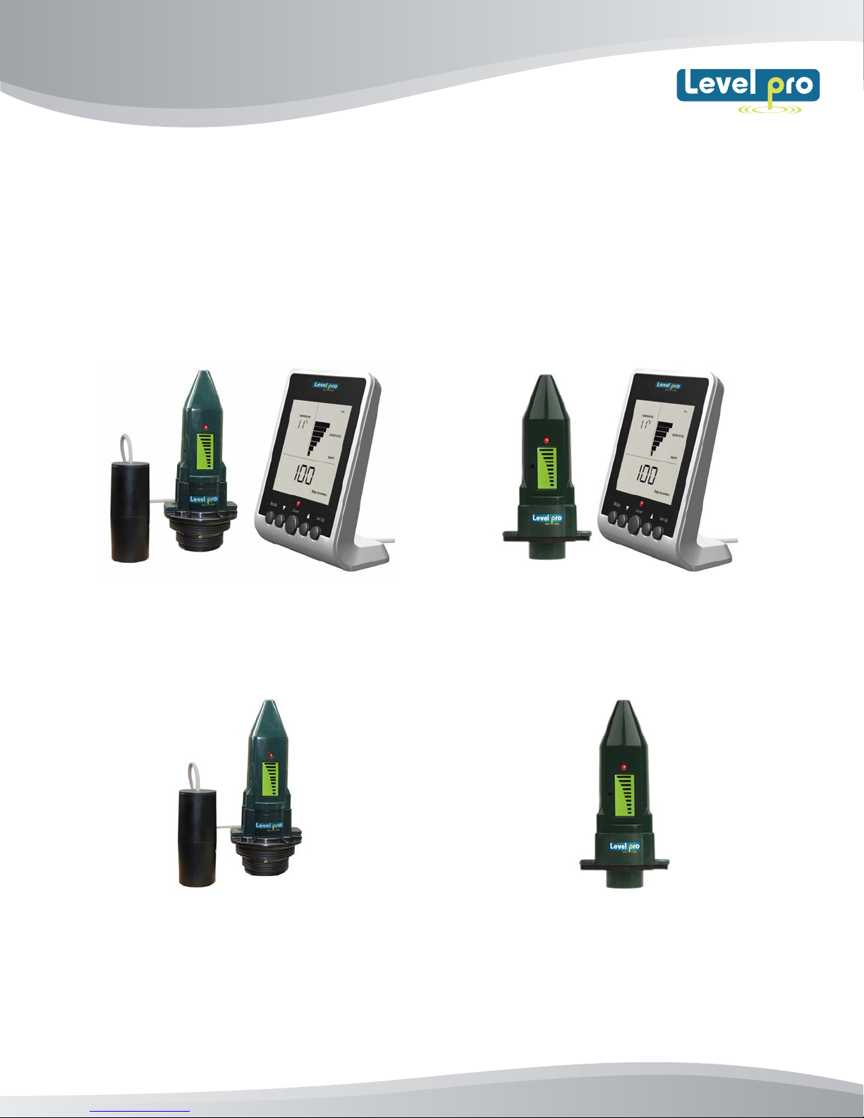
Ultrasonic Level Sensor (Models)
ViewSonic Level Sensor with
Leak Detection Switch + Remote Display
(Model VS1000-L)
ViewSonic Level Senor
c/w Leak Detection Switch
(Model VS500-L)
Read the user's manual carefully before starting to use the unit or software.
Levelpro reserves the right to implement changes without prior notice.
ViewSonic Level Sensor
with Remote Display
(Model VS1000)
ViewSonic Level Sensor
(Model VS500)
www.iconprocon.com
Page 2
ViewSonic
User Manual
ViewSonic Manual
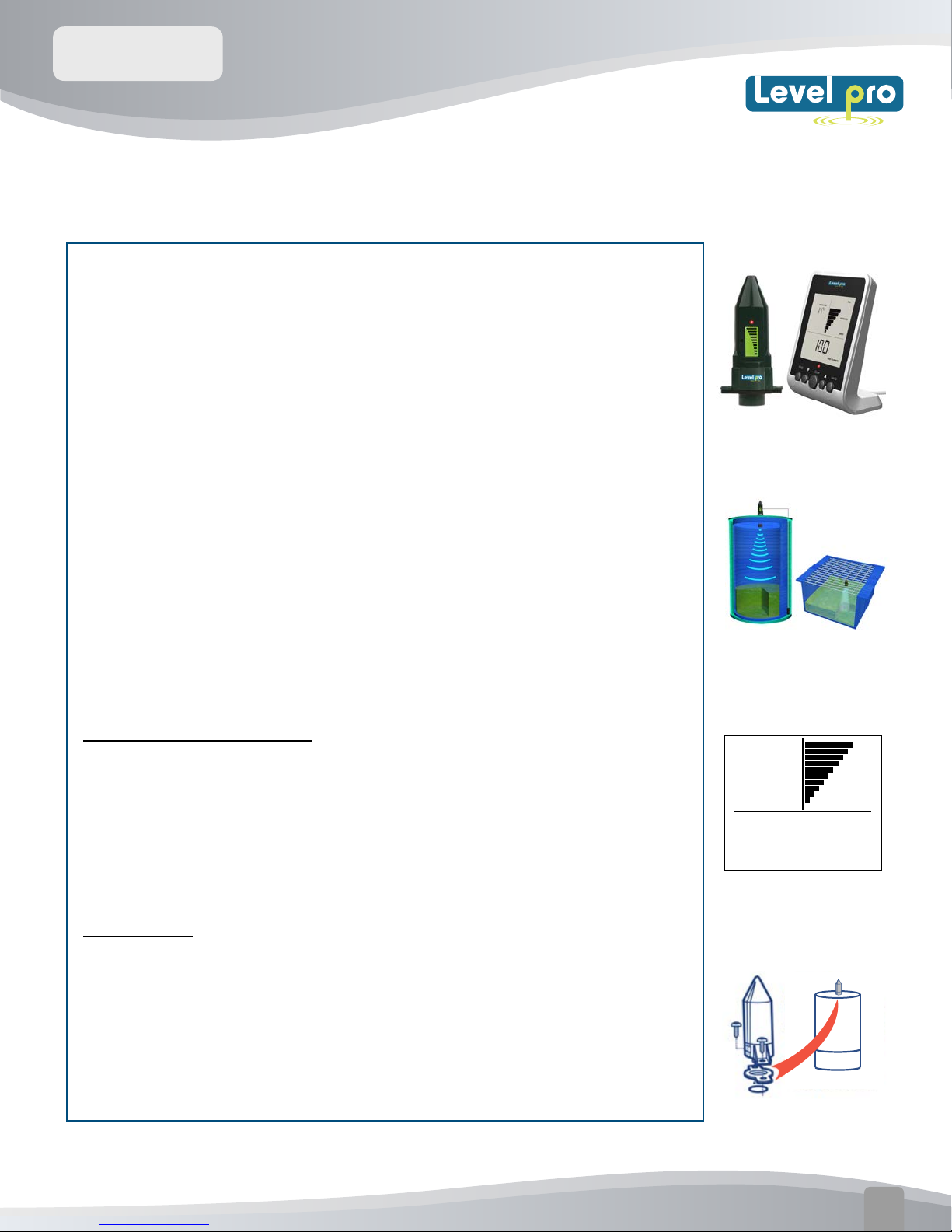
1. INTRODUCTION
The ViewSonic Sensor is a battery operated ultrasonic liquid
level sensor that is capable of providing the user with instant
level indication at a glance. The ViewSonic Transmitter uses
ultrasonic (sound wave) technology to measure the distance
from the sensor face to the surface of the liquid in chemical
tank or sump, then back to sensor face; this is referred to as
(time of flight) As the liquid product inside the tank decreases
the distance that the senor measures increases accordingly.
The current level measurement can be viewed directly on the
LCD screen located on the sensor or via the remote display.
No wiring is required as the level data is wirelessly
transmitted to the remote display.
Gallons / Inches / %
After completion of programming the display calculates and
displays the amount of liquid remaining in your tank in
gallons, inches or as a percentage of the tank capacity. In
addition
Mounting
ROOM TEMPERATURE
°F
2O
65O
FULL
LIQUID LEVEL
EMPTY
Gal
The ViewSonic sensor can be mounted directly on the top of
the tank, drum, tote and is suitable for use with any plastic
or metal tank up to 10' (3m) in height, including double
walled tanks.
www.iconprocon.com
Easy to Install
01
Page 3
ViewSonic
User Manual
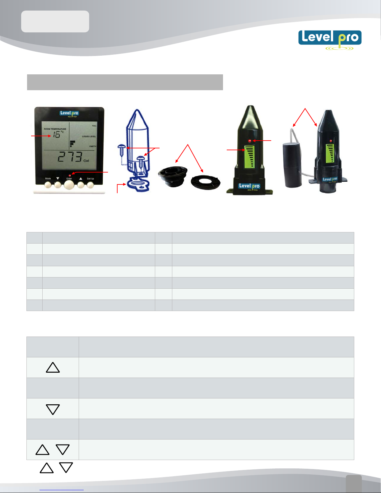
2. Viewsonic Level – Features and Functions
13
1
2 3 4 5 6
ViewSonic Features
1
LCD Display
2
MODE key
3
DOWN key
4
ENTER key
5
6
7
Key
UP
SETUP
Alarm Red LED
Key
8
9
7
10
8
9
10
11
12
13
11
12
10
ViewSonic Sensor
Self-tapping screws x 2
Weatherseal (Gasket)
Installation Fitting 2" , 1 1/2" NPT
ViewSonic Level display
ViewSonic Level + Leak Detection Switch
7
ViewSonic Key Functions
MODE
ENTER
SETUP
+
Note:
When the display is in 'NORMAL' mode press 'MODE' to move between the current and
the historical information screens.
Press 'UP' to move between screens when in 'NORMAL' mode to view Gal, In,
or % of current liquid level .Use it to increase a setting when in 'SETUP' mode.
The 'ENTER' key is used only during the 'SETUP' mode. Press to save the setting
shown on the display and then move automatically to the next 'SETUP' number.
Press 'DOWN' to move between screens when in 'NORMAL' mode to view Liquid
Level in Gal, In or %. Use it to decrease a setting when in 'SETUP' mode.
Press 'SETUP' for 3 seconds to enter 'SETUP'. When in
'SETUP', press 'SETUP' to exit from 'SETUP' mode.
When in 'NORMAL' mode, by press together and release, the screen will flash the
current tank configuration for 20 seconds.
PRESS
and HOLD UP or Down Arrows to Increase Selection Speed
www.iconprocon.com
02
Page 4
ViewSonic
User Manual
LED
The red light above the 'ENTER' key flashes when there is an Alarm condition (see section 6)
TANK TYPE
A
B C
ROOM TEMPERATURE
°F
LIQUID LEVEL
H
W
18888
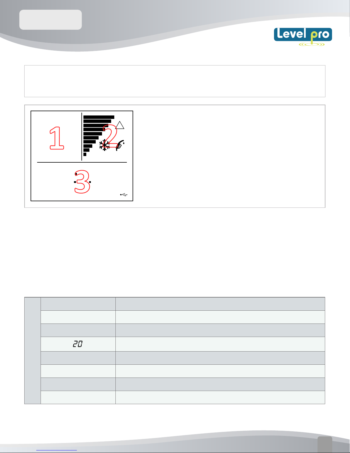
1.
Screen (1) displays Programming number, Tank Type -during normal operation
LEAK ALARM
%
in
Gal
/
FULL
!
EMPTY
DISPLAY - SYMBOLS & INDICATORS
The Viewsonic Display displays valuable information during
normal use and during its initial setup and configuration for use
with your tank. T
indicated in the diagram.
he display contains three sections (1, 2, & 3) as
displays room temperature.
2.
Provide Liquid Level information including a visual bar-graph tank.
3.
Information about the remaining usable liquid in Gal/Inches or % Tank Volume
ViewSonic Display features
TANK TYPE
A,B,C
ROOM TEMPERATURE
1
in
H
W
Indicates the Tank Type being selected
A, B,C refers to tank shapes (see section 5)
The value displayed is the Room Temperature where display is located
Numeric display - Shows the Room Temperature in normal mode e.g 20.
The value displayed is temperature in degrees Farenheit°F
The value displayed is in INCHES
The value displayed is the Tank Height ( Tanks A, B, C)
The value displayed is the tank width-(tank types B & C Only)
www.iconprocon.com
03
Page 5
ViewSonic
User Manual
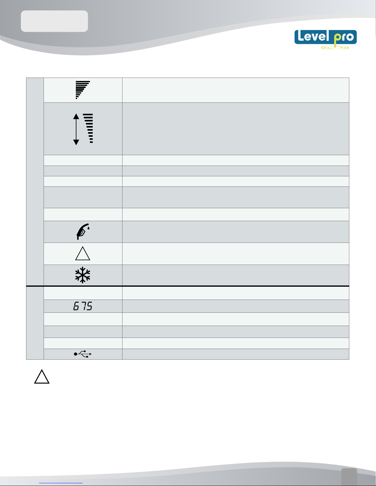
ViewSonic Monitor Display:
Bargraph indicator of liquid level - each bar represents 10% of tank height
ViewSonice Transmitter Display:
Tanks 10 ft (3m ) in height or greater - each bar represents 10 % of
tank height
2
3
FULL
LIQUID LEVEL
EMPTY
LEAK DETECTION
ALARM
TANK LOW BATTERY
!
%
Inches
Gallons
Time
Indicates the 'Full' level of tank/drum being measured
Indicates the LCD display bargraph current liquid level
Indicates the 'Empty' level of the tank/drum being measured
The flashing of the LED light and LCD bars indicates a leak has been
detected.
The ViewSonic Transmitter battery needs to be changed. (See page 11)
Flashing - Indicates that the liquid IeveI in the tank is at 10% or below of
tank height. (Appears on both the Viewsonic Display and Transmitter)
Flashing - There is a problem with the RF signal from the ViewSonic Sensor
(Appears on both the Display and Sensor)
The temperature is close to or below the limit of operation of the ViewSonic
Sensor - the accuracy and battery life of the sensor may be affected.
The value displayed is the % of liquid remaining in the tank.
Numeric display - used to show numeric values
Displayed value in Inches
Displayed value in Gallons
The value displayed in 24 Hour Clock
Note : Reset Button located on back of Viewsonic Display
!
USB data connection.
www.iconprocon.com
04
Page 6
ViewSonic
User Manual
3.PRODUCT INFORMATION
TECHNICAL SPECIFICATIONS:
Min.Height : 1.6 ft ( 0.5m)
Tank Size
Displays
Audible Alarm Audible alarm sounds every 60min (hourly) when the tank level is low
Max. Height: 10 Ft (3m)
Max. Ta
Multi-function LCD display including :
nk Volume: 5200 Gal (19999L)
• 10 bar-graph level indication on both ViewSonic Display and Sensor
• Display of various current and historical values (ViewSonic
• Red LED provides low level indication less than of liquid remaining
Display only)
Max communication
distance
Wireless
Communications
Power Supply - 3V LiMn cell, CR2450
Power Supply for
Display
Battery Life
Dimensions Sensor: 5.5" X 2.7" X 1.6" Display: 4.72" X 3.5" X 2"
Max and Min
Operation
(Transmitter)
Typically 200 Ft in normal ‘line of sight’ conditions
433MHz FM transmission (EN300-220)
120 VAC, 50-60 Hz, meets EN60950-1
Sensor : > 5 years (estimated life)
Display Monitor – approx 3yr of data
retention if display is not plugged in
Operating temperature range: -20°C to +60°C
Operating Humidity : 0 - 95% non-condensing
Hole size for
Fitting
Transmitter :
1.25" diameter
www.iconprocon.com
05
Page 7

ViewSonic
User Manual
4.DISPLAY SCREENS
Main Display Screen– provides current status of the liquid level of the tank., and allows for easy visual
display 'Gal' or ,‘%’, or ‘Days to empty’, as well the current time
ROOM TEMPERATURE
°F
2O
FULL
LIQUID LEVEL
EMPTY
Gal
ROOM TEMPERATURE
°F
2O
Press
LIQUID LEVEL
%
FULL
EMPTY
and
ROOM TEMPERATURE
2O
FULL
°F
LIQUID LEVEL
EMPTY
in
ROOM TEMPERATURE
°F
2O
Current Time
FULL
LIQUID LEVEL
EMPTY
5. TANK SETUP
In order calculate the volume in your tank the ViewSonic Display needs to know the shape of the tank.
There are three (3) basic shapes as illustrated below. Identify the shape that is closest to the shape of the
tank being measured. Each ViewSonic Display is supplied with the default settings as shown. The
ViewSonic Display must then be configured to match the tank’s dimensions that is goingto be measured
Type
Tank Capacity (Gallons)
Low
Limit
Default
High
Limit
Tank Height (in) Tank Width (in)
Low
Limit
Default
High
Limit
Low
Limit
Default
High
Limit
Type A
Type B
Type C
Tank
Width
N/A N/A N/A
Tank
Width
Tank
Height
www.iconprocon.com
Tank
Height
06
Page 8

ViewSonic
User Manual
6.LEVEL ALARMS / INDICATIONS
ROOM TEMPERATURE
°
F
2O
FULL
LIQUID LEVEL
ROOM TEMPERATURE
°
F
2O
FULL
Full Indication
LIQUID LEVEL
When the level in your tank is with
FULL
Gal
EMPTY
Lo
Gal
EMPTY
in 4" of the sensors transducter, the
main display will indicat
e ‘FULL’.
Low Level Indications
If tank level reaches a low level the ‘re-fill’ symbol will flash. When the tank level is below 10% of
the usable volume of liquid left in the tank, the CURRENT information screen alternates between
showing the' Gal' and will indicate ‘Lo’. on the display
If the Liquid level drops below 5% of liquid remaining :
‘Lo’ is displayed constantly on the Main screen.
The monitor there will be an audible beeps 5 times,
repeating every hourly,
The RED LCD light will b
egin to flash
ROOM TEMPERATURE
2O
°
F
Lo
LIQUID LEVEL
EMPTY
Gal
FULL
ROOM TEMPERATURE
2O
°
F
85
FULL
LIQUID LEVEL
EMPTY
Gal
This will continues until the tank is refilled with liquid
Leak Detection Alarm (Model with Leak Detection Boyancy Switch)
If the leak detection switch senses liquid it
will cause the red LED light and local LCD
display (bar graph) on the ViewSonic to
flash
If the remote ViewSonic display is utilized
the LCD (bar graph) and red LED light will
flash. An audible alarm will also become
active.
Press Enter to Cancel Audible Alarm on
mote Display
re
Note : LCD Bar graph,and LED Light will
continue to flash until upset alarm
condition is addressed and rectified
LCD Flashing +
Red LED LIght
www.iconprocon.com
07
Page 9

ViewSonic
User Manual
7. TRANSMITTER BATTERY CHANGE
If the battery in the ViewSonic Transmitter needs to be changed the display will
warning by showing the ‘TANK LOW BATTERY’ situated below the bargraph will begin to flash
Remove the ViewSonic Transmitter from the tank
The battery can be accessed by removing the four (4 )
screws from the base of the unit.
Remove the old battery and replace it with a new battery, 3V
CR2450 type
Please ensure the O-ring is not damaged - relocate in the
correct position.
Connect the ViewSonic transmitter to the top of the tank.
ROOM TEMPERATURE
provide advance
°
F
2O
65O
TANK LOW BATTERY
There is no need to 'Pair' the Sensor with the Display when the ViewSonic
Sensor battery is changed.
Disposal :
FULL
LIQUID LEVEL
EMPTY
Gal
The crossed out garbage symbol on the
treated as household waste.
Proper disposal will help prevent potentially negative consequences for the environment and human
health.
packaging indicates that this product and its battery shall not be
8.TROUBLESHOOTING
If the ViewSonic Display
understand
Sensor , an error message will be displayed on the
Display. The error message appears as an
alternating screen showing ‘Err’ and ‘E:0?’ where ? is
a number. Error codes are listed on a label on the
rear of your ViewSonic Display.
the RF signal from the Viewsonic
does not receive or cannot
ROOM TEMPERATURE
°
F
2O
Err
!
ROOM TEMPERATURE
°
F
2O
EO3
!
www.iconprocon.com
08
Page 10

ViewSonic
User Manual
Error Description To Rectify :
Check the transmitter is vertical on the tank.
EO1
E02
E03
Received
reading is
onsistent
inc
Reading not
received after
6 hours
Reading
received but
void
Check positioning of the transmitter (ensure the transmitter is not too close to
the tank sides or internal obstructions).
Ensure that the transmitter is not too tightly attached to the tank.
Ensure that the tank is not overfilled and that the bottom of the transmitter is
clean.
Check the transmitter is within range of the monitor. Try and relocate the
monitor to a position that is nearer a window, remember that the transmitter
communicates with the monitor by use of an FM signaland moving the
monitor plug from possible metalobstructions can improve the signal.
Check that there are no metal obstruction that may deflect the signal.
Ensure the monitor is not too close to, or obstructed by, other electrical
appliances.
Check positioning of the transmitter (ensure the transmitter is not too close to
the tank sides or internal obstructions).
Ensure that the transmitter is not too tightly attached to the tank.
Ensure that the tank is not overfilled i.e. there is a minimum of 4 inches
free space between the transmitter and level.
Ensure the bottom of sensor is clean.
Check the tank height and ensure this information is correct on the monitor,
press the 6. and V keys together to view your tank configuration. If height is
Received
E04
EO5
EO6
Reading
greater than
tank heigh
Contact
Vendor
Contact
Vendor
t
incorrect, enter the setup mode by pressing SETUP for thre seconds,
ss ENTER until you reach screen 5 and adjust the height using 6. and V keys.
pre
P
ress ENTER to save. Press SETUP to exit Setup mode. Wait 3 hours for updated
readings.
Check the transmitter is vertical and the positioning of the transmitter (ensure
the transmitter is not too close to the tank sides or internal obstructions).
This is a hardware fault please contact your distributor
This is a hardware fault please contact your distributor
www.iconprocon.com
09
Page 11

ViewSonic
User Manual
TROUBLESHOOTING (con't)
a. Blank Screen
Pairing my not have activated correctly or battery may need to be replaced.
Repeat Step 3 or replace battery. If problem continues contact technical
support
b. Full Screen but tank not full
Viewsonic Sensor may not be positioned 90 degrees vertically on tank to the
liquid. Ensure sensor is vertical. Clear any obstacles in field of vision of the
sensor.
c. Middle Bar + Flashing Triangle
Indicates lost ultrasonic echo. Ensure transducer ( sensing ) face is wiped
clean. Sensor not Vertical- Ensure sensor is positioned 90 degress to liquid.
d. Low Battery Signal
Triangle - Not Flasing = Low Battery.
Remove ViewSonic sensor from the tank
1.
Access the battery by removing the 4 sst screws from the
2.
underside of the ViewSonic sensor
Remove and replace with a new battery (3VCR2450)
3.
(Note + side up)
Replace upper cover with screws (do not overtighten) Ensure
4.
O-Ring is in place and not damaged.
Reinstall the Viewsonic Sensor
5.
Ensure (+
Pos) Sign is
Visual Low Level Indication
facing out
!
!
Empty
Almost
Empty
Full50% Full
www.iconprocon.com
10
Page 12

ViewSonic
User Manual
Installation Guide-Programming
ViewSonic
Battery Operated Ultrasonic
Level Sensor + Display + Leak Detection Switch
Your tank/Drum/Sump
Dimension Chart
Type A - Rectangular/
cylindrical vertical
Type B - (H >= W) Oval/
cylindrical horizontal
Tank
Type
Height
(H) ins.
Width
(W)
N/A
ins.
Brimful
pacity
Ca
(Gls.)
Nominal
Capacity
(Gls.)
(95% of Brimful)
Type C - (W > H) Lo profile
STEP 1 - DETERMINE THE SHAPE OF YOUR TANK/DRUM/
Select the tank type that most closely matches the vessel you are using from the above chart
Determine the dimensions of your tank either from the manufacturer or by physically
measuring the Tank /Drum /Sump/Tote
For Double Walled Tanks Only the Internal Dimensions and Type (Chart) are required
The tank height, will be measured from the top of the tank, i.e. where the ViewSonic Level
sensor will be mounted, to the bottom of the tank
(Note: Ensure the ViewSonic sensor is installed on the top of the internal tank if using a
double walled tank.)
www.iconprocon.com
11
Page 13

ViewSonic
User Manual
STEP 2 – Programming DISPLAY
When first turning on the ViewSonic Dispay it will display the SETUP mode -In the top left
corner. Setup1. During the Programing Phase you will be guided through the Setup via
flashing screens. The 'Programming' is very intuitive and it is very easy to configure the display
to your specific application.
Note: that if you enter incorrect information simply continue to press ENTER until you are back
to the correct step where you can enter the correct value and press ENTER to store.
ENTER
Time
Minutes
Tank Type
Tank Capacity
Tank Height
OFT- Range Distance from
Sensor Face to Max Fill Height
Hours
FAST
ENTER
Minutes
FAST
ENTER
Type A - B - C
FAST
ENTER
Gallons
FAST
ENTER
Tank Type A-Height Only For Tank
Type B & C Tank 'W" Width Required
FAST
ENTER
Inches (max 88")
FAST
OLH- Span- Height of Sludge or
Sediment in bottom of tank
AL
ENTER
FAST
ENTER
FAST
Inches (max 15")
On _Off
www.iconprocon.com
12
Page 14

ViewSonic
User Manual
TANK TYPE
A
SETUP
SETUP 1 – Setting the time (hrs)
Adjust the hour displayed using
/ . Press ENTER to save.
SETUP
Gal
SETUP 4 – Programming the
tank/drum/sump capacity (ltr./
Gal.) Enter the number in litres/
gallons then Press ENTER t
o save
SETUP
SETUP 2 – Setting the time (mins)
Adjust minutes displayed using
/ .
Press ENTER to save.
TANK TYPE
B
SETUP
H
in
SETUP 5 – Programming tank/
drum/sump height (ins.)
Press ENTER to save. Note that
if Tank
Type ‘A’ was selected,
SETUP 6 will be skipped
.
SETUP
SETUP 3 – Programming the tank
type Select tank type A, B, or C,
using / . to ma
then Press ENTER to save.
TANK TYPE
B
SETUP
SETUP 6 (Type B & C tanks only)
Programming the in (inches)
Press ENTER t
W
o save.
ch your tank
t
in
N.B. If you unable to measure your tank /sump / drum please confirm that you have selected the correct type...A-B or C
Setup 7
Programming Offset -OFT you are able to program the distance freom the Sensor face to the maximum
level of the liquid. This is measured in 'inches' and can be set from 0-19" Span
SETUP
OFt
SETUP
2
in
max fill height
OFT
OFT Distance from
Sensor Face to max
fill Height
Setup 8
Programming Range -OFH
The Viewsonic Display can be programmed to account for sediment or sludge build-up located at the
bottom of the tank.
8
SETUP
Input value
8
SETUP
Off Set to account
for Buildup sludge or
sediment inside tank.
OLH
2
Sludge or Sediment Build-up
www.iconprocon.com
OFH
13
Page 15

ViewSonic
User Manual
SETUP
9
SETUP
9
Press and
SETUP
9
On
OFF
Setup 9 – Programming the-Leak Detection Visual +Audible Alarm
Alarm on : When a leak is sensed the ViewSonic Display will sound an audible beep and the
LCD Display will flash on the sensor as well as on the display. The LED red light on the sensor
will also light up and flash. The Audible sound can be turned off by pressing Enter
Alarm off : Turn alarm notification off .
Select AL ON/OFF using / . When the display shows your preferred setting press ENTER to save.
SETUP is now complete. Press SETUP to exit and progress to STEP 3.
On exiting Programming mode the monitor temporarily displays ‘CALC’.
Note: If at any stage during the Programming stage you exit SETUP mode , simply press and
hold the SETUP button for at least 3 seconds to begin again.
STEP 3 - Pairing THE Sensor TO THE Display
ROOM TEMPERATURE
°F
2O
Lrn
Image 1 : ‘Lrn’ mode Image 2 : Alignment Pin
The Display must be in Pairing Mode (Lrn) mode which can
be entered in one of two ways:
A) Pressing SETUP after completing STEP 2 above
B)
Disconnecting and reconnecting the power. The Pairing
mode (Lrn) the display shows ‘Lrn’ in the main screen area
(image 1). Pairing mode will last for approx 2 minutes during
which time you must ‘match/pair’ the sensor to the display.
On
Image 3 : Correct positioning Image 4 : Alignment
Continue to hold the transmitter and monitor together
LrnLrnLrn
Image 4 : Syncing
The sensor LCD display should be facing in the same direction as the
LCD on the display as shown in image #4 base of the display.
Step 1 Position Sensor with Display-Hold for approx 5-10 Second
Step 2 If after 10 seconds syncing does not occur ( see Image 4)
Remove Sensor from Display for approx 5 seconds.-(Depending
on conditions this step may need to be repeated )
Step 3 Reposition Sensor with the Display (Image 3) Hold in place.
Once the units are connected the LCD bars on both the display and the
sensor with climb in sync while bars climb in sync, and audible beep is
emitted-This will indicate that the pairing is complete
www.iconprocon.com
14
Page 16

ViewSonic
User Manual
After the pairing’ is complete the sensor will send level data continuously to the display for approximately
ten (10 minutes). Every time the display receives data from the sensor a audible clicking noise will sound
and the red LED light will flash on the ViewSonic Sensor
The pairing procedure can be confirmed by slowly lowering and raising the
flat surface and observing that the display reflects the changes. The ‘Quick-Click’ mode will stop after 10
minutes. The Viewsonic Sensor is now ready to mounted onto the tank/drum/ sump .
Note: Keep the Sensor Perpendicular to the surface being measured
ViewSonic level sensor over a
STEP 4 - INSTALLING the ViewSonic Senor
Tanks with pre-drilled hole
A 2" or 1 1/2" MNPT Bulkhead fitting is provide for threading
directly onto the tank.
Ensure the trans
Ensure the LCD Bar Graph is displaying current liquid level
Note: if after 10 minutes the sensor is not mounted , the
an incorrect reading. It may take 1-2 hours before the correct level data is shown on the display screen.
mitter is vertical to the liquid on top of the tank.
display may show the error symbol or display
www.iconprocon.com
15
Page 17

ViewSonic
User Manual
Installation Tips
Do not insert a down tube or
stillwell or any other object.
Aviod obstacles such as
ladders or mixers inside
the tank/sump
or dru
m
The transmitter must
be mounted vertical
Your ViewSonic display and Level Sensor is now complete.
Wireless
Remote Display
Up to 200 ft Away
Battery OperatedViewSonic > 5 + Years
Battery Life
Leak Detection
Ensure Sensor is Perpendicular
to Liquid Level
Contact Details
Should you have any questions, please contact
us : www.iconprocon.com
1-905 -469 9283
sales@ico
The contents and images in this guide are subject to copyright and may not be
reproduced without the permission of Icon Process Controls Ltd
nprocon.com
www.iconprocon.com
16
Page 18

Notes & Calculations
Page 19

Icon Process Controls
www.iconprocon.com
www.SellingSolutionsFirst.com
905 469 9283
Page 20

ViewSonic
Battery Operated Level Sensors
Wireless Displays
Leak Detection Switches
+
+
 Loading...