

Page 1
CD4233
LCD Commercial Display
- User Guide
- Guide de l’utilisateur
- Guía del usuario
- Bedienungsanleitung
3\ɤɨɜɨɞɫɬɜɨɩɨɥɶɡɨɜɚɬɟɥɹ
ĮġٺҢЙы
Model No.: VS13510
Page 2
ViewSonic CD4233
Declaration of RoHS Compliance
This product has been designed and manufactured in compliance with Directive 2002/95/
EC of the European Parliament and the Council on restriction of the use of certain
hazardous substances in electrical and electronic equipment (RoHS Directive) and is
deemed to comply with the maximum concentration values issued by the European
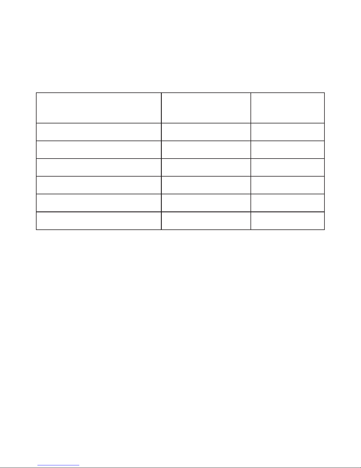
Technical Adaptation Committee (TAC) as shown below:
Substance
Proposed Maximum
Concentration
Actual Concentration
Lead (Pb) 0.1% < 0.1%
Mercury (Hg) 0.1% < 0.1%
Cadmium (Cd) 0.01% < 0.01%
Hexavalent Chromium (Cr6+) 0.1% < 0.1%
Polybrominated biphenyls (PBB) 0.1% < 0.1%
Polybrominated diphenyl ethers (PBDE) 0.1% < 0.1%
Certain components of products as stated above are exempted under the Annex of the
RoHS Directives as noted below:
Examples of exempted components are:
0HUFXU\LQFRPSDFWÀXRUHVFHQWODPSVQRWH[FHHGLQJPJSHUODPSDQGLQRWKHUODPSV
QRWVSHFL¿FDOO\PHQWLRQHGLQWKH$QQH[RI5R+6'LUHFWLYH
/HDGLQJODVVRIFDWKRGHUD\WXEHVHOHFWURQLFFRPSRQHQWVÀXRUHVFHQWWXEHVDQG
electronic ceramic parts (e.g. piezoelectronic devices).
3. Lead in high temperature type solders (i.e. lead-based alloys containing 85% by weight
or more lead).
4. Lead as an allotting element in steel containing up to 0.35% lead by weight, aluminium
containing up to 0.4% lead by weight and as a cooper alloy containing up to 4% lead by
weight.
i
Page 3

ViewSonic CD4233
Copyright Information
Copyright© ViewSonic Corporation, 2010. All rights reserved.
ViewSonic, the three birds logo, OnView, ViewMatch, and ViewMeter are registered
trademarks of ViewSonic Corporation.
ENERGY STAR®is a registered trademark of the U.S. Environmental Protection Agency (EPA).
As an ENERGY STAR
®
partner, ViewSonic Corporation has determined that this product meets
the ENERGY STAR
®
JXLGHOLQHVIRUHQHUJ\HI¿FLHQF\
Disclaimer:ViewSonic Corporation shall not be liable for technical or editorial errors or
omissions contained herein; nor for incidental or consequential damages resulting from
furnishing this material, or the performance or use of this product.
In the interest of continuing product improvement, ViewSonic Corporation reserves the right
WRFKDQJHSURGXFWVSHFL¿FDWLRQVZLWKRXWQRWLFH,QIRUPDWLRQLQWKLVGRFXPHQWPD\FKDQJH
without notice.
No part of this document may be copied, reproduced, or transmitted by any means, for any
purpose without prior written permission from ViewSonic Corporation.
Product Registration
To meet your future needs, and to receive any additional product information as it becomes
available, please register your product on the Internet at: www.viewsonic.com.
For Your Records
Product Name:
Model Number:
Document Number:
Serial Number:
Purchase Date:
CD4233
ViewSonic 42” LCD Commercial Display
VS13510
CD4233_UG_ENG Rev. 1A 04-27-10
______________________________
______________________________
Product disposal at end of product life
ViewSonic is concerned about the preservation of our environment. Please dispose of
this product properly at the end of its useful life. Your local waste disposal company may
provide information about proper disposal.
The lamp in this product contains mercury. Please dispose of properly in accordance with
environmental laws of your location.
1
Page 4

CONTENTS
———————————————————————————————————————————————
SAFETY INSTRUCTIONS...............................................................................................................3
Package Contents..........................................................................................................................9
Parts Name and Functions..........................................................................................................10
Control Panel...........................................................................................................................................................10
Terminal Panel ......................................................................................................................................................... 11
Remote Control .......................................................................................................................................................12
Operating Range for the Remote Control................................................................................................................13
Handling the remote control ....................................................................................................................................13
Setup Procedure ..........................................................................................................................14
How to Mount and Attach Feet to the LCD Monitor...................................................................16
Connectivity .................................................................................................................................19
Connectivity Diagram ..............................................................................................................................................19
Connecting to a Personal Computer .......................................................................................................................20
Connecting to a Digital Interface Equipment...........................................................................................................21
Connecting to a DVD Player....................................................................................................................................22
Connecting to a Stereo Amplifier.............................................................................................................................23
Connecting to a display mounted PC ......................................................................................................................23
Basic Operation ...........................................................................................................................24
Power ON and OFF Modes.....................................................................................................................................24
Power Indicator........................................................................................................................................................25
Using Power Management ......................................................................................................................................25
Display Signal of Video Source Setting to [VIDEO].................................................................................................25
Picture Size..............................................................................................................................................................25
Smart Picture Mode.................................................................................................................................................26
Audio Source Switching...........................................................................................................................................26
Control Lock Mode ..................................................................................................................................................26
OSD Information......................................................................................................................................................26
OSD (On-Screen-Display) Controls ............................................................................................27
PICTURE.................................................................................................................................................................28
SCREEN..................................................................................................................................................................30
AUDIO .....................................................................................................................................................................32
PIP (PICTURE IN PICTURE) ..................................................................................................................................33
CONFIGURATION 1 ................................................................................................................................................34
CONFIGURATION 2 ................................................................................................................................................35
ADVANCED OPTION ..............................................................................................................................................36
NOTE.......................................................................................................................................................................38
Features........................................................................................................................................40
Troubleshooting ...........................................................................................................................41
Specifications...............................................................................................................................43
ViewSonic CD4233
2
Page 5
SAFETY INSTRUCTIONS
WARNINGS AND PRECAUTIONS
KNOW THESE SAFETY SYMBOLS
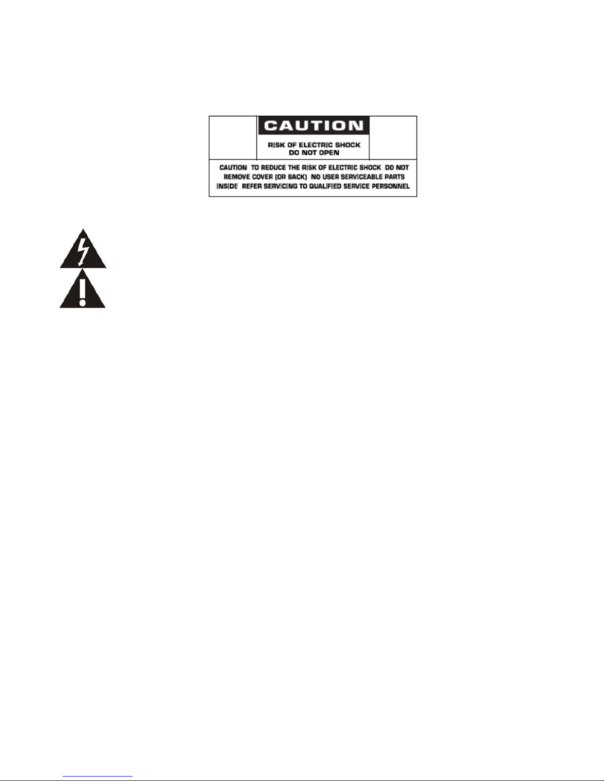
CAUTION: TO REDUCE THE RISK OF ELECTRIC SHOCK, DO NOT REMOVE COVER (OR BACK). NO USER
SERVICEABLE PARTS INSIDE. REFER SERVICING TO QUALIFIED SERVICE PERSONNEL.
This symbol indicates high voltage is present inside. It is dangerous to make any kind of contact with any
inside part of this product.
This symbol alerts you that important literature concerning operation and maintenance has been included
with this product.
Caution: FCC/CSA regulations state that any unauthorized changes or modifications to this equipment may void the user’s
authority to
operate it.
Caution: To prevent electric shock, match the wide blade of plug to the wide slot, and fully insert the plug.
Attention: Pour éviter les chocs électriques, introduire la lame la plus large de la fiche dans la bome correspondante de la prise et
pousser jusqu’au fond.
TO PREVENT DAMAGE WHICH MAY RESULT IN FIRE OR ELECTRIC SHOCK HAZARD, DO NOT EXPOSE THIS
APPLIANCE TO RAIN OR MOISTURE.
The Socket-outlet shall be installed near the apparatus and shall be easily accessible.
Read and follow these instructions when connecting and using your computer monitor:
z Unplug the monitor if you are not going to use it for an extensive period of time.
z Unplug the monitor if you need to clean it with a slightly damp cloth. The screen many be wiped with a dry cloth
when the power is off. However, never use alcohol, solvents or ammonia-based liquids.
z Consult a service technician if the monitor does not operate normally when you have followed the instructions in
this manual.
z The casing cover should be opened only by qualified service personnel.
z Keep the monitor out of direct sunlight and away from stoves or any other heat source.
z Remove any object that could fall into the vents or prevent proper cooling of the monitor’s electronics.
z Do not block the ventilation holes on the cabinet.
z Keep the monitor dry. To avoid electric shock, do not expose it to rain or excessive moisture.
z If turning off the monitor by detaching power cable or DC power cord, wait for 6 seconds before attach the power
cable or DC power cord for normal operation.
z To avoid the risk of shock or permanent damage to the set do not expose the monitor to rain or excessive
moisture.
z When positioning the monitor, make sure the power plug and outlet are easily accessible.
z IMPORTANT: Always activate a screen saver program during your application. If a still image in high contrast
remains on the screen for an extended period of time, it may leave an ‘after-image’ or ‘ghost image’ on the front of
the screen. This is a well-known phenomenon that is caused by the shortcomings inherent in the LCD technology.
In most cases the afterimage will disappear gradually over a period of time after the power has been switched off.
Be aware that the after-image symptom cannot be repaired and is not covered under warranty.
ViewSonic CD4233
3
Page 6
REGULATORY INFORMATION
CE DECLARATION OF CONFORMITY
MMD declare under our responsibility that the product is in conformity with the following standards
• EN60950-1:2006+A11:2009 (Safety requirement of Information Technology Equipment)
• EN55022:2006+A1:2007 (Radio Disturbance requirement of Information Technology Equipment)
• EN55024:1998+A1:2001+A2:2003 (Immunity requirement of Information Technology Equipment)
• EN6100-3-2: 2006 (Limits for Harmonic Current Emission)
• EN6100-3-3:1995+A1:2001+A2:2005 (Limitation of Voltage Fluctuation and Flicker) following provisions of directives applicable
• 2006/95/EC (Low Voltage Directive)
• 2004/108/EC (EMC Directive)
• 93/68/EEC (Amendment of EMC and Low Voltage Directive) and is produced by a manufacturing organization on ISO9000 level.
FEDERAL COMMUNICATIONS COMMISSION (FCC) NOTICE (U.S. Only)
This equipment has been tested and found to comply with the limits for a Class B digital device, pursuant to Part 15 of the
FCC Rules. These limits are designed to provide reasonable protection against harmful interference when the equipment
is operated In a commercial environment. This equipment generates, uses and can radiate radio frequency energy and, if
not installed and used in accordance with the instructions manual, may cause harmful interference to radio
communications.
Operation of this equipment in a residential area is likely to cause harmful interference in which case the user will be required to
correct the interference at his own expense.
Changes or mod
ifications not expressly approved by the party responsible for compliance could void the user’s authority to
operate the equipment.
Use only RF shielded cable that was supplied with the monitor when connecting this monitor to a computer device.
To prevent damage which may result in fire or shock hazard, do not expose this appliance to rain or excessive moisture.
THIS CLASS B DIGITAL APPARATUS MEETS ALL REQUIREMENTS OF THE CANADIAN INTERFERENCE- CAUSING
EQUIPMENT REGULATIONS.
T
his device complies with Part 15 of the FCC Rules. Operation is subject to the following two conditions: (1) this device
may not cause harmful interference, and (2) this device must accept any interference received, including interference that may
cause undesired operation.
ViewSonic CD4233
4
Page 7
POLISH CENTER FOR TESTING AND CERTIFICATION NOTICE
The equipment should draw power from a socket with an attached protection circuit (a three-prong socket). All equipment that
works
together (computer, monitor, printer, and so on) should have the same power supply source.
The phasing conductor of the room’s electrical installation should have a reserve short-circuit protection device in the form of a fuse
with
a nominal value no larger than 16 amperes (A).
To completely switch off the equipment, the power supply cable must be removed from the power supply socket, which should be
located near the equipment and easily accessible.
A protection mark “B” confirms that the equipment is in compliance with the protection usage requirements of standards PN-93/T42107 and PN-89/E-06251.
ViewSonic CD4233
5
Page 8
INFORMATION FOR UK ONLY
WARNING - THIS APPLIANCE MUST BE EARTHED.
Important:
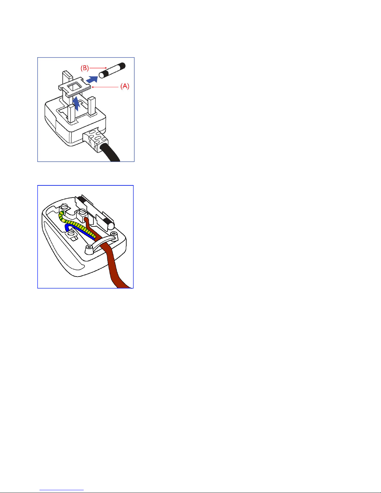
This apparatus is supplied with an approved moulded 13A plug. To change a
fuse in this type of plug proceed as follows:
1. Remove fuse cover and fuse.
2. Fit new fuse which should be a BS 1362 5A,A.S.T.A. or BSI approved type.
3. Refit the fuse cover.
If the fitted plug is not suitable for your socket outlets, it should be cut off and an
appropriate 3-pin plug fitted in its place.
If the mains plug contains a fuse, this should have a value of 5A. If a plug
without a fuse is used, the fuse at the distribution board should not be greater
than 5A.
Note: The severed plug must be destroyed to avoid a possible shock hazard
should it be inserted into a 13A socket elsewhere.
How to connect a plug
The wires in the mains lead are coloured in accordance with the following code:
BLUE - “NEUTRAL” (“N”)
BROWN - “LIVE” (“L”)
GREEN & YELLOW - “EARTH” (“E”)
1. The GREEN AND YELLOW wire must be connected to the terminal in
the plug which is marked with the letter “E” or by the Earth symbol or
coloured GREEN or GREEN AND YELLOW.
2. The BLUE wire must be connected to the terminal which is marked with the
letter “N” or coloured BLACK.
3. The BROWN wire must be connected to the terminal which marked with the
letter“L” or coloured RED.
Before replacing the plug cover, make certain that the cord grip is clamped over
the sheath of the lead - not simply over the three wires.
ViewSonic CD4233
6
Page 9
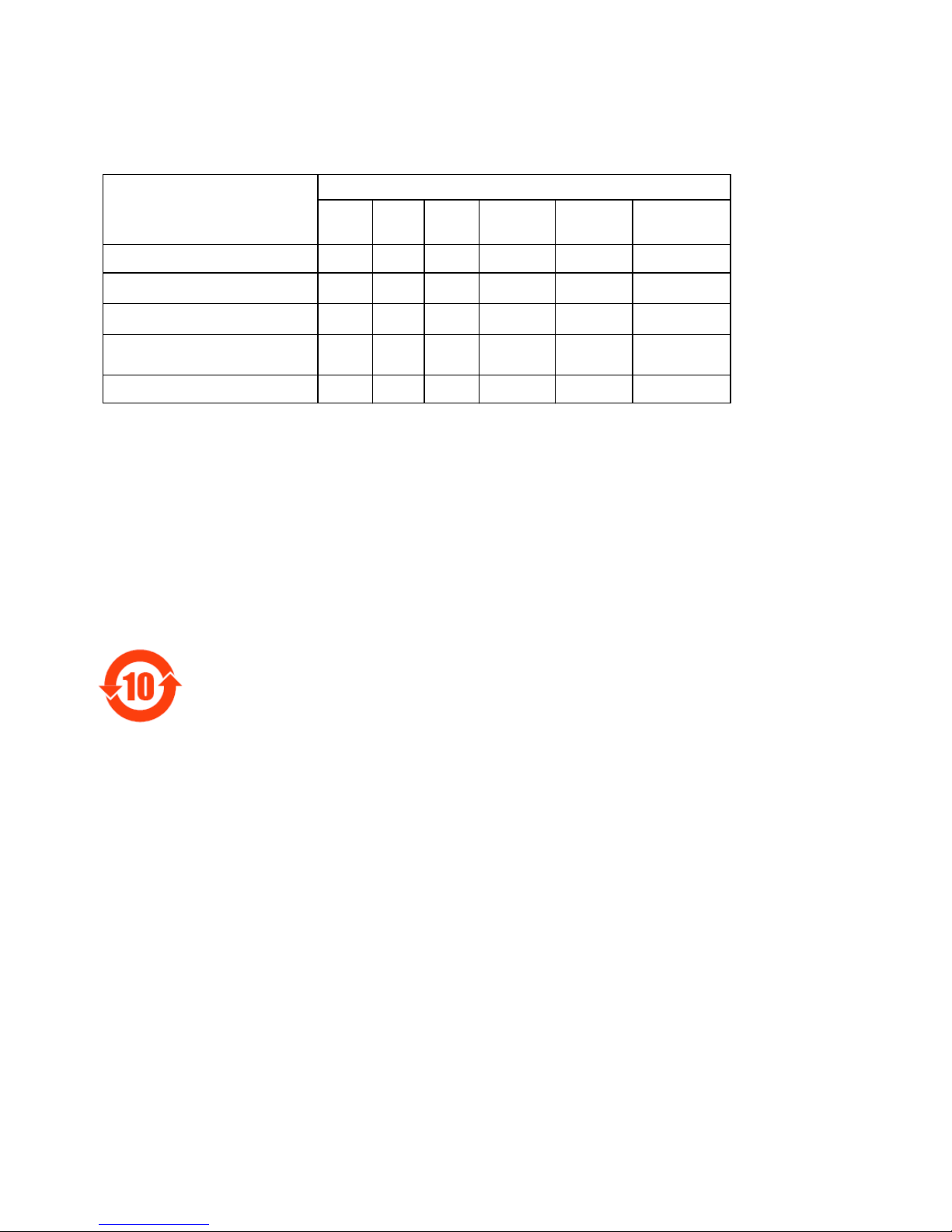
Ё⬉ᄤֵᙃѻક∵ᶧࠊ䆚㽕∖(ЁRoHS⊩㾘⼎㽕∖)ѻકЁ᳝↦᳝ᆇ⠽䋼
ܗ㋴ⱘৡ⿄ঞ䞣
᳝↦᳝ᆇ⠽䋼ܗ㋴
䚼ӊৡ⿄
䪙
(Pb)∲(Hg)䬝(Cd)
݁Ӌ䫀
(Cr 6+)
⒈㘨㣃
(PBB)
⒈Ѡ㣃䝮
(PBDE)
ƻƻƻ ƻ ƻ ƻ
⎆䴶ᵓ
hh
ƻƻ ƻ ƻ
⬉䏃ᵓ㒘ӊ
h
ƻƻ ƻ ƻ ƻ
䰘ӊ
!
)䘹఼ǃ⬉⑤㒓ǃ䖲㒓*
h
ƻƻ ƻ ƻ ƻ
䘹఼⬉∴
h
ƻƻ ƻ ƻ ƻ
ƻ˖ 㸼⼎䆹᳝↦᳝ᆇ⠽䋼䆹䚼ӊ᠔᳝ഛ䋼ᴤ᭭Ёⱘ䞣ഛSJ/T11363-2006ޚ㾘ᅮⱘ䰤䞣㽕∖
ҹϟ
DŽ
h˖ 㸼⼎䆹᳝↦᳝ᆇ⠽䋼㟇ᇥ䆹䚼ӊⱘᶤϔഛ䋼ᴤ᭭Ёⱘ䞣䍙ߎSJ/T11363-2006 ޚ㾘ᅮⱘ䰤
䞣㽕∖
DŽ
⦃ֱՓ⫼ᳳ䰤
ℸ䆚ᣛᳳ䰤(ᑈ)ˈ⬉ᄤֵᙃѻકЁ᳝ⱘ᳝↦᳝ᆇ⠽䋼ܗ㋴ℷᐌՓ⫼ⱘᴵӊϟϡӮথ⫳
⊘さবˈ⬉ᄤֵᙃѻક⫼᠋Փ⫼䆹⬉ᄤֵᙃѻકϡӮᇍ⦃๗䗴៤Ϲ䞡∵ᶧᇍ݊Ҏ䑿ǃ䋶ѻ䗴៤
Ϲ䞡ᤳᆇⱘᳳ䰤DŽ
ViewSonic CD4233
7
Page 10

NORTH EUROPE (NORDIC COUNTRIES) INFORMATION
Placering/Ventilation
VARNING:
FÖRSÄKRA DIG OM ATT HUVUDBRYTARE OCH UTTAG ÄR LÄTÅTKOMLIGA, NÄR DU STÄLLER DIN UTRUSTNING PÅPLATS.
Placering/Ventilation
ADVARSEL:
SØRG VED PLACERINGEN FOR, AT NETLEDNINGENS STIK OG STIKKONTAKT ER NEMT TILGÆNGELIGE.
Paikka/Ilmankierto
VAROITUS:
SIJOITA LAITE SITEN, ETTÄ VERKKOJOHTO VOIDAAN TARVITTAESSA HELPOSTI IRROTTAA PISTORASIASTA.
Plassering/Ventilasjon
ADVARSEL:
NÅR DETTE UTSTYRET PLASSERES, MÅ DU PASSE PÅ AT KONTAKTENE FOR STØMTILFØRSEL ER LETTE Å NÅ.
END-OF-LIFE DISPOSAL
Your new TV/Monitor contains materials that can be recycled and reused. Specialized companies can recycle your product to increase the
amount of reusable materials and to minimize the amount to be disposed of.
Please find out about the local regulations on how to dispose of your old monitor from your local Viewsonic dealer.
(For customers in Canada and U.S.A.)
This product may contain lead and/or mercury. Dispose of in accordance to local-state and federal regulations. For additional information on
recycling contact www.eia.org (Consumer Education Initiative)
WASTE ELECTRICAL AND ELECTRONIE EQUIPMENT-WEEE
Attention users in European Union private households
This marking on the product or on its packaging illustrates that, under European Directive 2002/96/EG
governing used electrical and electronic appliances, this product may not be disposed of with normal
household waste. You are responsible for disposal of this equipment through a designated waste electrical
and electronic equipment collection. To determine the locations for dropping off such waste electrical and electronic, contact your
local
government office, the waste disposal organization that serves your household or the store at
which you purchased the product.
Attention users in United States:
Like all LCD products, this set contains a lamp with Mercury. Please dispose of according to all Local, State and Federal Laws. For the disposal
or recycling information, contact: www.mygreenelectronics.com or www.eiae.org.
ViewSonic CD4233
8
Page 11
Package Contents
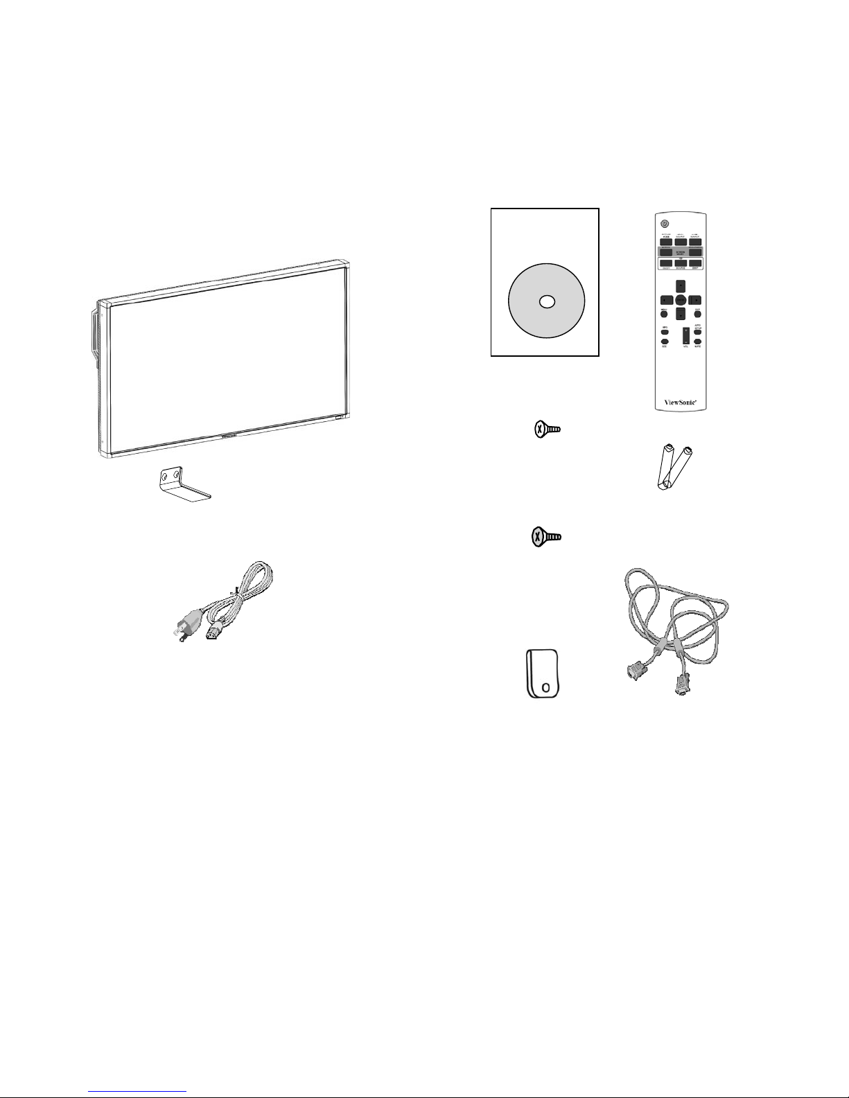
The LCD monitor pack* should include:
• LCD monitor
Video Signal Cable
(D-SUB to D-SUB Cable)
• Power cord (1.8 m)
• VGA Signal Cable (1.8 m)
• CD User Manual & QSG
• Remote Control and AAA Batteries
• Main switch cover
• Screw for Main Switch cover x 6
• Clamper x 2
• Screw for Clamper x 2
Xxxxxxxxxxxx
xx
xxxxxxxxxxxx
xxxxxxxxxxxx
xxxxxxxxx
Screw for Clamper
(M4 x 8) x 2
CD Use
r
Manual & QSG
Sc
r
ew forMain switch cove
r
(M3 x 5) x 6
Main switch cove
r
Remote Con
t
r
ol and AAA
Batteries
* The supplied power co
r
d varies depending on destination.
Clamper x 2
For North
America
Power cord
*
Please make sure that for
all
other
regions, apply a
power cord thatconforms to
the
AC
voltage of the power socket and has been approved by and complies with
the safety regulations of the particular country.
* You might like to save the package box and packing material for shipping the
monitor.
* The foll
owing components are prepared as options.
• External
Speakers
• Table
stand
ViewSonic CD4233
9
Page 12
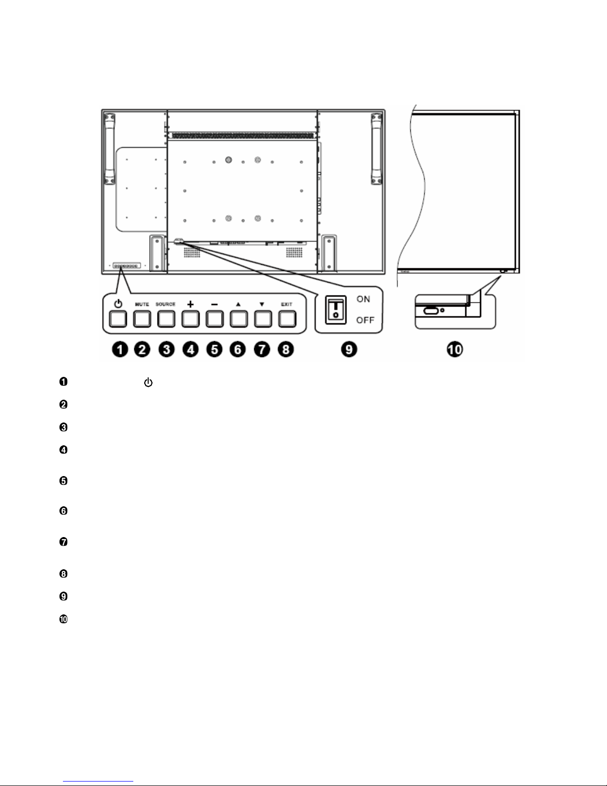
Parts Name and Functions
Control Panel
POWER button ( ) : To switch the power on/off.
MUTE button : To switch the audio mute ON/OFF.
SOURCE button : To set the function while OSD menu is on or to activate input selection menu while OSD menu is off.
PLUS (+) button : To increase the adjustment while OSD menu is on, or to increase the audio output level while the OSD menu is
off.
MINUS (-) button : To decrease the adjustment while OSD menu is on, or to decrease the audio output level while the OSD menu is
off.
UP (S) button : To move the highlight bar up to adjust the selected item while OSD menu is on, or to activate the OSD menu when
the OSD menu is off.
DOWN (T) button :To move the highlight bar down to adjust the selected item while OSD menu is on, or to activate the OSD
menu when the OSD menu is off.
EXIT button : To return to previous menu while OSD menu is on or to activate the OSD menu when the OSD menu is off.
Main Power Switch : To turn the main power on/off.
Remote control sensor, Power indicator and ambient light sensor : To receive the IR signal from the remote control.
The indicator would show green when the LCD monitor is active and would turn red when the LCD is POWER OFF. While in the case of
the system is in power save mode, it would show both green and red. When SCHEDULE is enabled, it would blink green and glow red.
If the indicator blinks red , it tells that a failure is detected.
The image brightness will be auto adjusted when “LIGHT SENSOR” set to “ON”
on OSD menu.
NOTE: Keyboard Control Lock Mode This function completely disables the access to all Keyboard Control functions. To enable
the keyboard control lock, press both of “S” and “T” buttons and hold down continuously for more than 3 seconds. To recover back to the
user mode, press both of “S” and “T” and hold continuously for three 3 seconds.
ViewSonic CD4233
10
Page 13
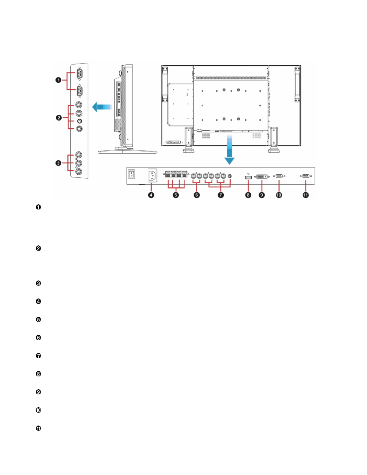
Terminal Panel
EXTERNAL CONTROL (mini D-Sub 9 pin)
This is for serial connection when multiple monitors are connected. To achieve remote management through RS232C commands (refer to
the RS232C remote control user manual), connect the RS232C OUT connector from a computer or from a different monitor to the
RS232C IN connector from your monitor. The same RS232C commands can be looped through by connecting the RS232C OUT of this
monitor to the next RS232C IN.
VIDEO IN/OUT
VIDEO IN connector (BNC and RCA): To input a composite video signal. Note that BNC and RCA are not available at the same time.
VIDEO OUT connector (BNC): To output the composite video signal from VIDEO IN connector.
S-VIDEO IN connector (MINI DIN 4 pin): To input the S-video (Y/C separate signal).
COMPONENT IN [Y, Pb, Pr] (BNC)
To connect an equipment such as a DVD player, HDTV device, or Laser disc player.
AC IN connector
To connect with the supplied power cord.
EXTERNAL SPEAKER TERMINAL
To output the audio signal to external speakers from AUDIO IN 1, 2, 3 jack or HDMI.
AUDIO OUT
To output the audio signal from the AUDIO IN 1,2 and 3 jack or HDMI.
AUDIO IN 1, 2, 3
To input audio signal from external equipment such as a computer, VCR or DVD player.
HDMI IN
To input digital video/audio signals from a digital equipment or computer.
DVI-D IN
To input digital video signals from a digital equipment or computer.
VGA IN (mini D-Sub 15 pin)
To input analog RGB signals from a computer or other RGB equipment.
VGA OUT (mini D-Sub 15 pin)
To output the signal from VGA IN.
ViewSonic CD4233
11
Page 14
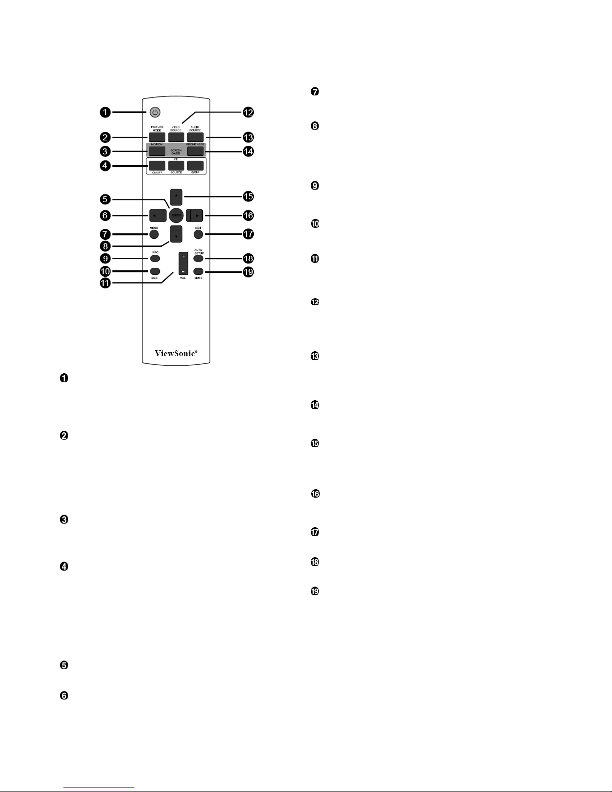
Remote Control
MENU button
To turn the OSD menu on/off.
DOWN button
To move the highlight bar down to adjust the selected item when
OSD menu is on.
T
o move the sub-picture down when in “PIP” mode.
INFO. button
To turn on/off the setting information displayed on the right-up
corner of the screen.
SIZE button
To select the picture size from [FULL], [NORMAL], [CUSTOM] ,
[DYNAM IC] and [REAL].
VOLUME button
VOLˇ button: To increase the audio output level.
VOL
ˉ
button˗To decrease the audio output level
VIDEO SOURCE button
To activate input selection menu, and push “S” or “T” to select
input source from [HDMI], [DVI-D], [VGA],[COMPONENT],
[S-VIDEO] and [VIDEO], and then push “ENTER” to switch to
selected input source.
AUDIO SOURCE button
To activate audio selection menu, and push “S” or “T” to select
audio source from [AUDIO1], [AUDIO2], [AUDIO3] and [HDMI], and
then push “ENTER” to switch to selected audio source.
POWER button
To turn the power on/off.
BRIGHTNESS button
If LED Pow
er Indicator on the monitor is not lightening, then the
remote control will not work.
T
o start the BRIGHTNESS OSD selection, and then push "
ُ
" or "ٙ"
button to adjust the value.
PICTURE MODE button
UP button
To select smart picture mode from [HIGHBRIGHT], [STANDARD],
To move the highlight bar up to adjust the selected item when OSD
menu is on.
[sRGB], [CINEMA].
HIGHBRIGHT: for moving image such as Video
T
o move the sub-picture up when in “PIP” mode.
ST
ANDARD: for images (Factory setting)
RIGHT button
sRGB: for text based images
CINEMA: for movies.
To increase the adjustment with OSD menu.
MONTION button
T
o move the sub-picture right when in “PIP” mode.
EXIT button
To expanded image slightly and moves 4 directions
(up,down,right,left) periodically
To turn to the previous OSD menu.
AUTO SETUP button
PIP (Picture In Picture) button
To execute the AUTO ADJUST function.
ON/OFF button: To turn PIP mode ON/OFF.
MUTE button
SOURCE button: To select the input signal for the sub-picture.
SWEP button: To exchange between the main picture and sub-
picture.
To turn the mute function on/off.
Note:
The “PIP” and “POP” modes do not work if the screen size is
“CUSTOM” , “DYNAMIC” or “REAL”.
ENTER button
To activate the setting with OSD menu.
LEFT button
To decrease the adjustment with OSD menu.
To move the sub-picture left when in “PIP” mode.
ViewSonic CD4233
12
Page 15
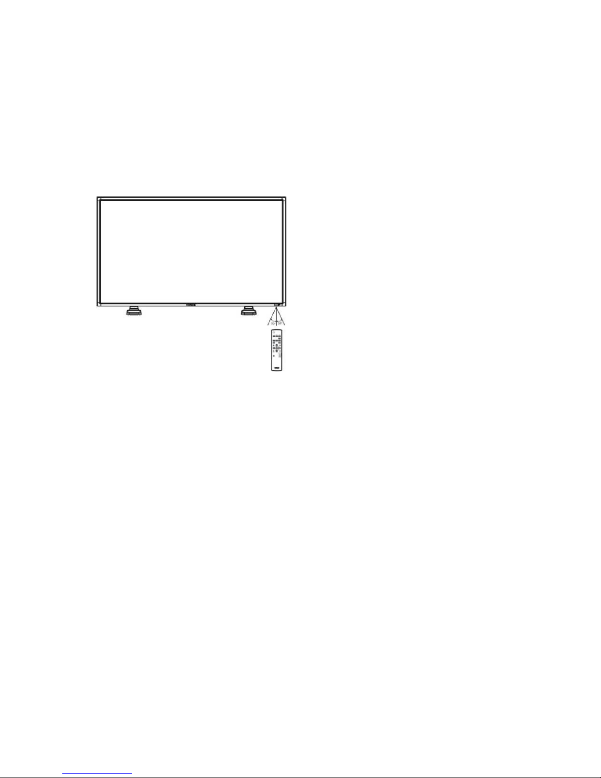
Operating Range for the Remote
Control
Handling the remote control
* Do not subject to strong shock.
* Do not allow water or other liquid to splash the remote
control. If the remote control gets wet, wipe it dry
immediately.
Point the top of the remote control towards the LCD monitor's remote
sensor during button operation.
Use the remote control within a distance of about 7 m/ 23 ft from the
front of the LCD monitor's remote control sensor and within a
horizontal and vertical angle 30° with a distance of about 3 m/ 10 ft.
* Avoid exposure to heat and steam.
* Other than to install the batteries, do not open the remote
control.
NOTE:
The remote control system may not function when direct sunlight or
strong illumination strikes the remote control sensor of the LCD
monitor, or when there is an obstacle in the radiation path.
ViewSonic CD4233
13
Page 16
Setup Procedure
1. Install the system on the right location
CAUTION:
THE LCD MONITOR MUST BE MOVED OR INSTALLED BY
TWO OR MORE PERSONS.
Failure to follow this caution may result in injury and damage
when the LCD monitor falls.
CAUTION:
DO NOT ATTEMPT TO INSTALL THE LCD MONITOR BY
YOURSELF.
The LCD display must be installed by a qualified technician.
Contact your dealer for more information.
CAUTION:
DO NOT MOUNT OR OPERATE THE DISPLAY UPSIDE
DOWN, FACE UP OR FACE DOWN.IT’S POSSIBILITY TO
CLOCKWISE 90 DEGREES MOUNT. BUT DO NOT
COUNTERCLOCKWISE 90 DEGREES MOUNT.
CAUTION:
DO NOT INSTALL THE LCD MONITOR WHERE IT WILL BE
EXPOSED TO DIRECT SUNLIGHT.
Failure to follow this caution will result in display defects.
IMPORTANT:
Lay the protective sheet, which was wrapped around the LCD
monitor when it was packaged, beneath the LCD monitor so as
not to scratch the panel.
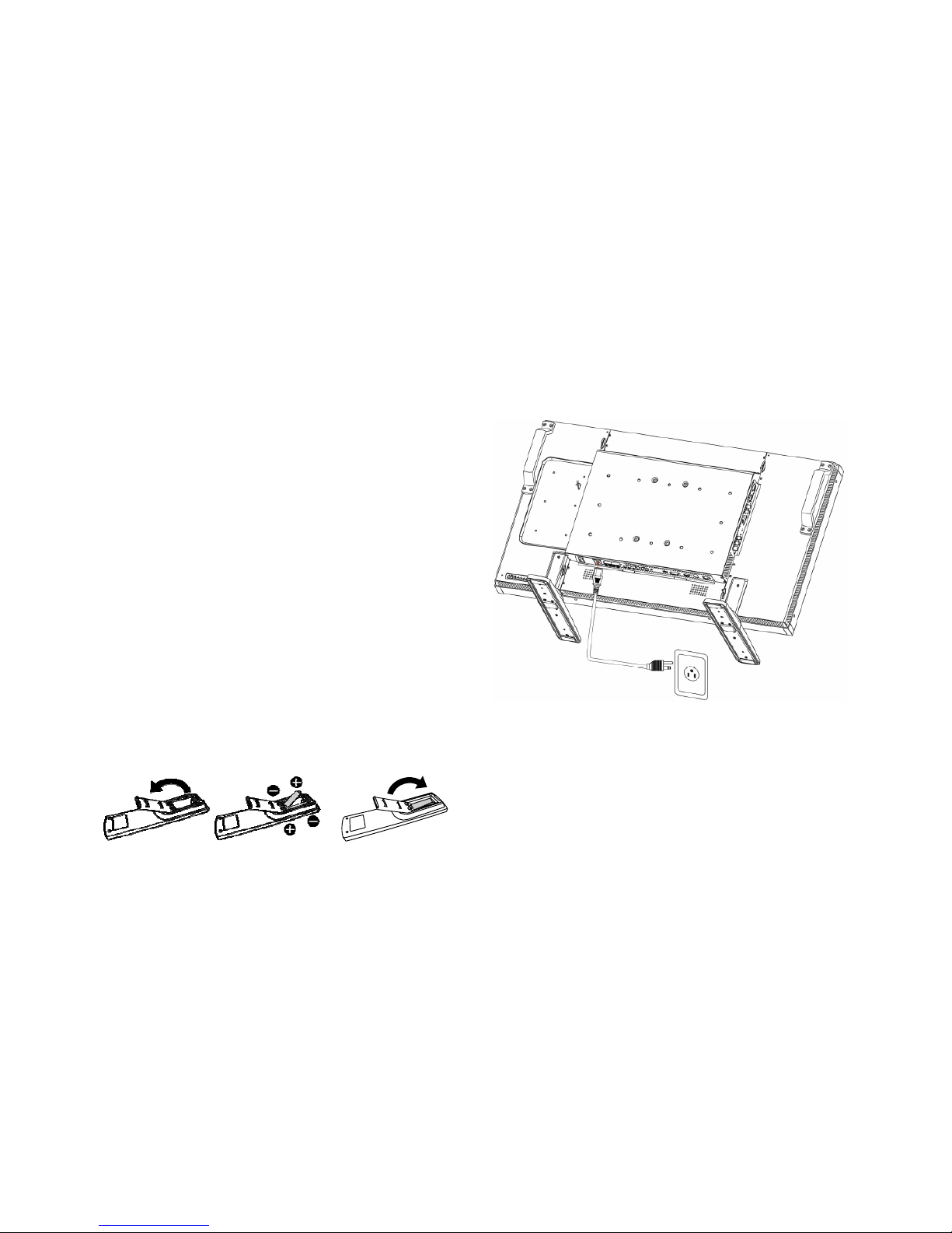
2. Install the remote control batteries
The remote control is powered by 1.5V AAA batteries. To install
or replace batteries:
1. Press and slide to open the cover.
2. Align the batteries according to the (+) and (–) indications
inside the case.
3. Replace the cover.
CAUTION:
Incorrect use of batteries can result in leaks or bursting. Be
careful especially about the following points.
• Place “AAA” batteries matching the + and - signs on each
battery to the + and - signs of the battery compartment.
• Do not mix battery types.
• Do not combine new batteries with used ones. It causes
shorter battery life or leakage of batteries.
• Remove dead batteries immediately to prevent battery liquid
from leaking into the battery compartment. Don't touch
exposed battery acid, it cause damage to your skin.
NOTE:
If you do not intend to use the Remote Control for a long period,
remove the batteries.
3. Connect to external equipment
• To protect the connected equipment, turn off the main power
before making connections.
• Please refer to section “Connectivity” P.18~P.22 for operations.
4. Connect power cord
• The power outlet socket should be installed as near to the
equipment as possible, and should be easily accessible.
• Fully insert the prongs into the power outlet socket. A loose
connection may cause malfunctioning of the device.
NOTE:
Please refer to “Safety Operation” section of this manual for proper
selection of AC power cord.
5. Turn on the power of the attached
external equipment
When connected with a computer, turn on the power of the
computer first.
6. Operate the attached external equipment
Display the signal from the external equipment by selecting the
correct video and audio sources first.
7. Adjust the sound
Make adjustments to lower or to rise the volume as required.
8. Adjust the screen
Make adjustments to the display position or settings if required.
ViewSonic CD4233
14
Page 17
9. Adjust the image
Make adjustments to brightness or contrast if required.
10. Recommended Adjustment
To reduce the risk of “image persistence”, please adjust the following items based on the application being used.
“POWER SAVE”, “PANEL SAVING”, “DATE AND TIME”.
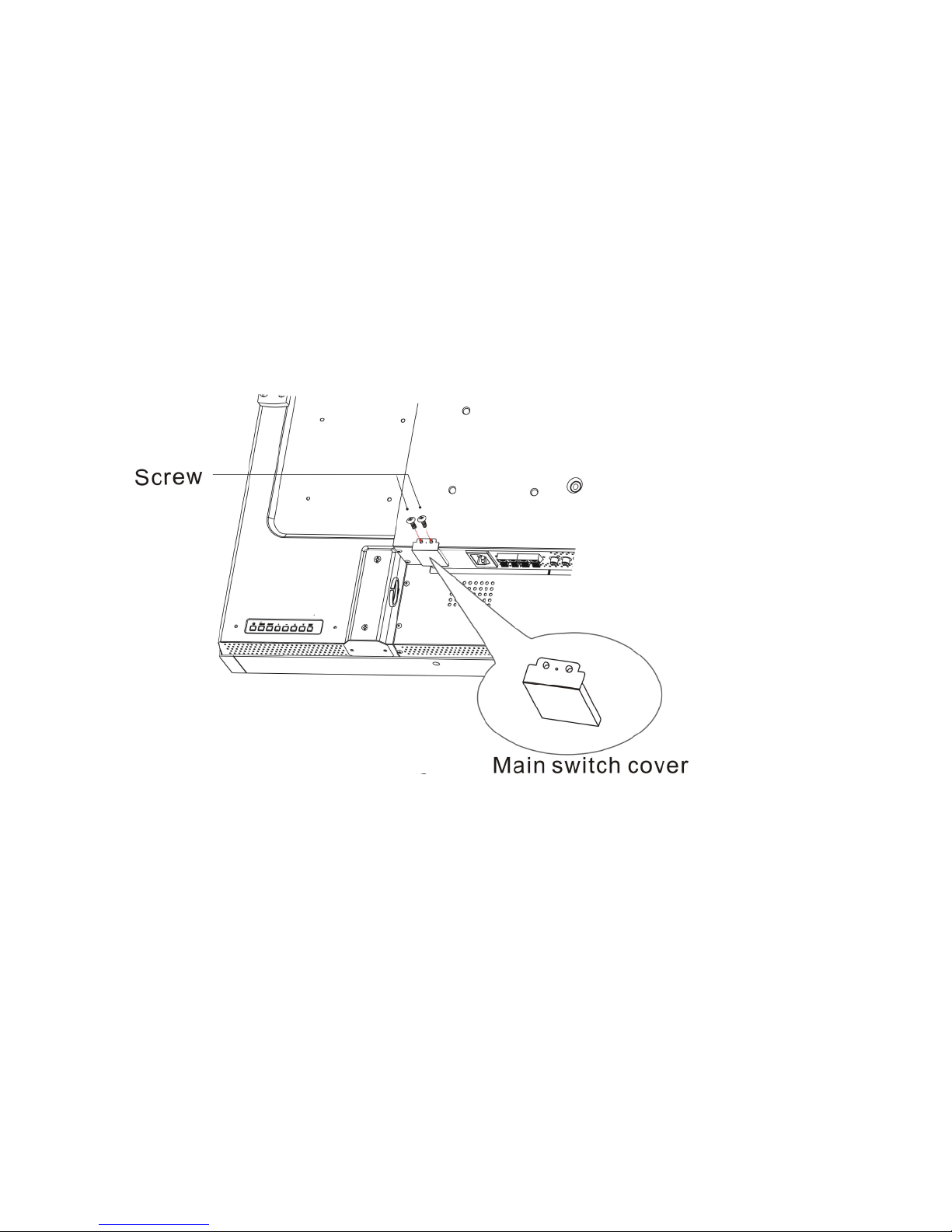
11. To prevent the main power switch from being changed
To prevent the possibility of main power switch being carelessly pushed, please attach the main switch cover (accessory) onto it.
NOTE:
With the main
power switch cover in place, the main power switch can not be turned off. Remove main power switch cover in order to
turn off the display.
ViewSonic CD4233
15
Page 18
How to Mount and Attach Feet to the LCD Monitor
You can install the LCD monitor in one of the following two ways:
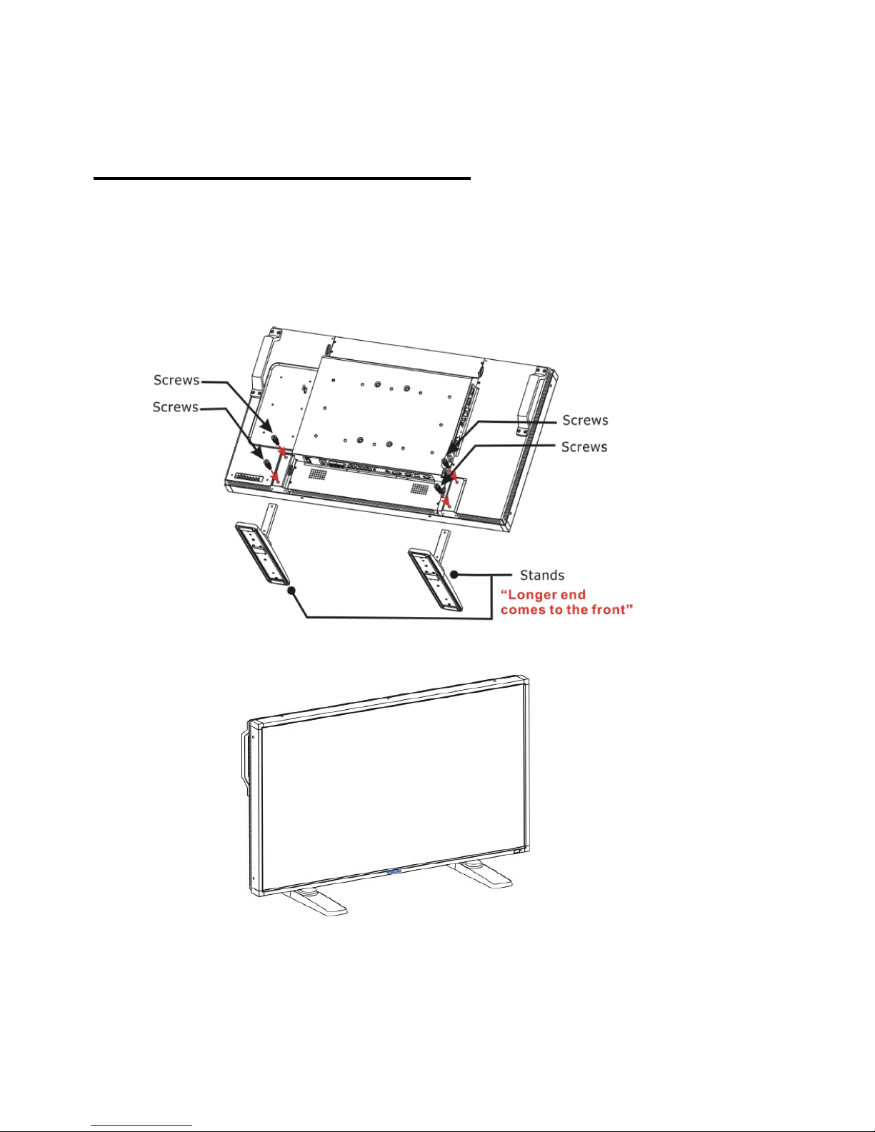
Method 1: Attach and remove the optional stands
How to install stands
1. Please turn the monitor off.
2. After inserting stand in guide block, fasten the thumbscrews on both sides of the monitor.
NOTE:
Install the table stand with the longer end of the feet directing to the front.
In the upright
position
How to remove the stands
1. Spread the protective sheet on the flat surface.
2. Make the monitor lying on the protective sheet.
3. Remove screws using a screwdriver and place them in a safe place for reuse.
ViewSonic CD4233
16
Page 19
To avoid monitor from falling
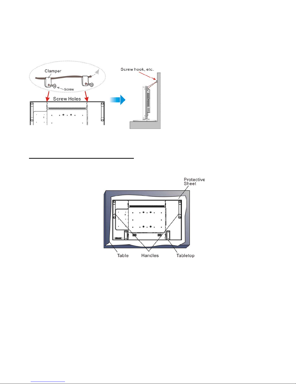
Take measures to prevent the monitor from falling over in case of an earthquake or other disaster might occur to lessen the probability of
injury and damage.
As shown in the figure below, secure the monitor to a solid wall or pillar using rope (commercially available) strong enough to bear the
weight of the monitor( approx. 47.5 kg). Screw hooks (commercially available), of ring type rather than C-shaped screw hooks (with
opening), are recommended.
Screw here is not supplied.
C
aution:
y Though the recommended prevention from falling is intended to lessen the probability of injury and damage, it doesn’t assure its
effectiveness against any kind of earthquake or disaster.
y Before moving the monitor, remove the rope that is securing the monitor.
Method II: Mount the monitor on the wall
Before mounting the monitor to the wall, make sure that the system has been power-off and you have obtain a standard wall-mounting kit
(commercially available). Using mounting interface that comply with TÜV-GS and/or UL1678 standard in North America is recommended.
1. Lay a protective sheet on a table, which was wrapped around the monitor when it was packaged, beneath the surface as not to scratch
the screen face.
2. This device cannot be installed without the correct and complete mounting accessories (not provided in the box). Make sure you have
all related parts available for wall mounting.
3. Follow the instructions that come with the base mounting kit. Failure to follow correct mounting procedures could result in damage to
the equipment or injury to the user or installer. Product warranty does not cover damage caused by improper installation.
4. For the wall-mounting kit, use M6 mounting screws for 400x 400 mm pattern (having a length 10 mm longer than the thickness of the
mounting bracket) and tighten them securely. (Recommended torque: 470 - 635N•cm).
Caution:
For preventing the monitor from falling.
y Install the monitor with metal brackets for wall or ceiling installation (commercially available) on your own responsibility. For detailed
procedures of installation, refer to the instructions of the metal brackets.
y To lessen the probability of injury and damage resulting from fall of the monitor in case of earthquake or other disaster, be sure to
consult the bracket manufacturer for installation location.
y To lessen the risk of falling of the monitor, thread commercially available rope (having a load capacity at least 1960N (200kgf)) through
the handles at the right and left of the monitor and secure the rope to the wall mount brackets or ceiling mount brackets.(Refer to the
first paragraph of this page.)
ViewSonic CD4233
17
Page 20
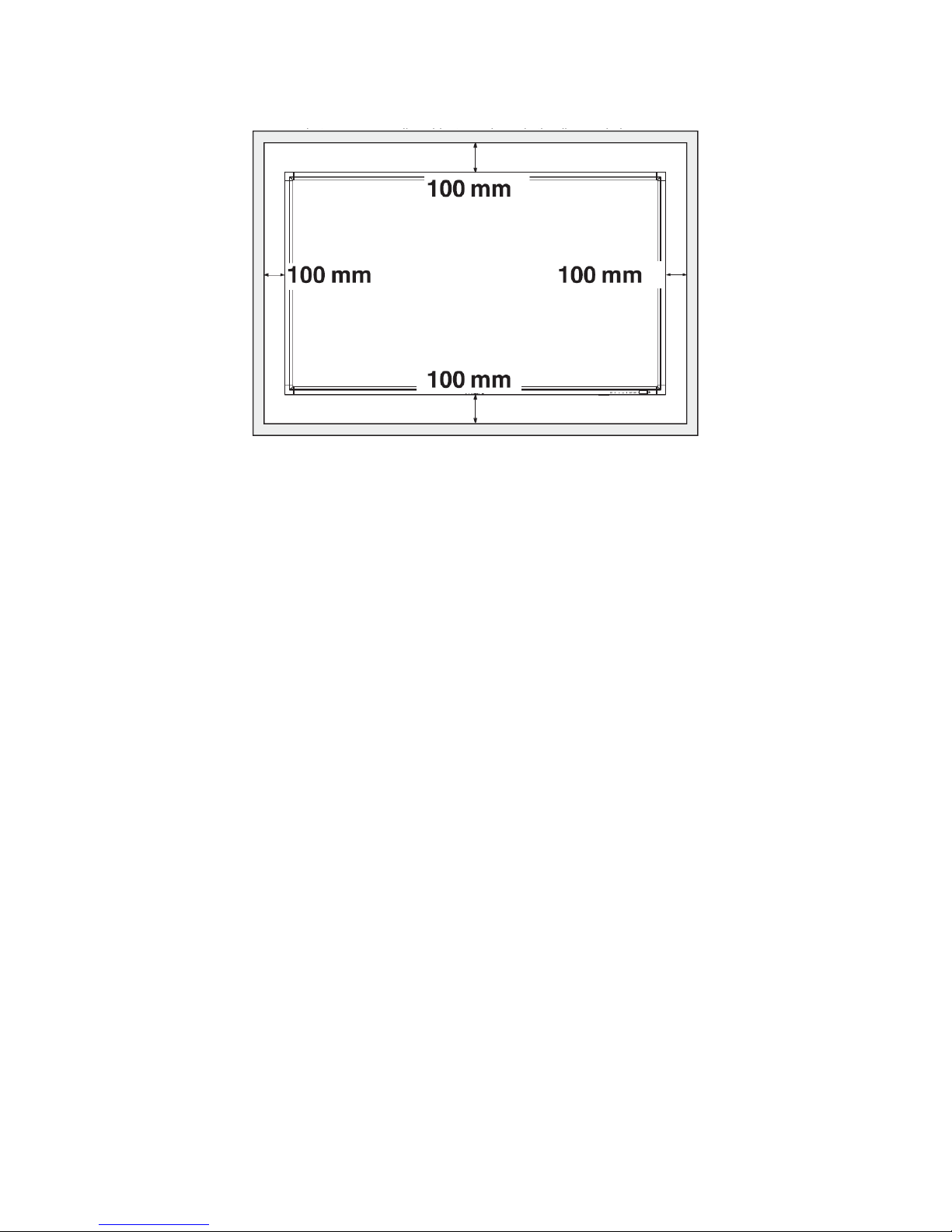
Ventilation Requirements for enclosure locating
To allow heat to disperse, leave space between surrounding objects as shown in the diagram below.
ViewSonic CD4233
18
Page 21
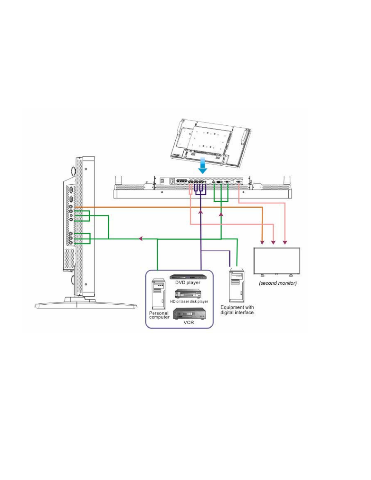
Connectivity
Before making connections:
* First turn off the power of all the attached equipments before make connections.
* Refer to the user manual included in each separate piece of equipment.
Connectivity Diagram
ViewSonic CD4233
19
Page 22
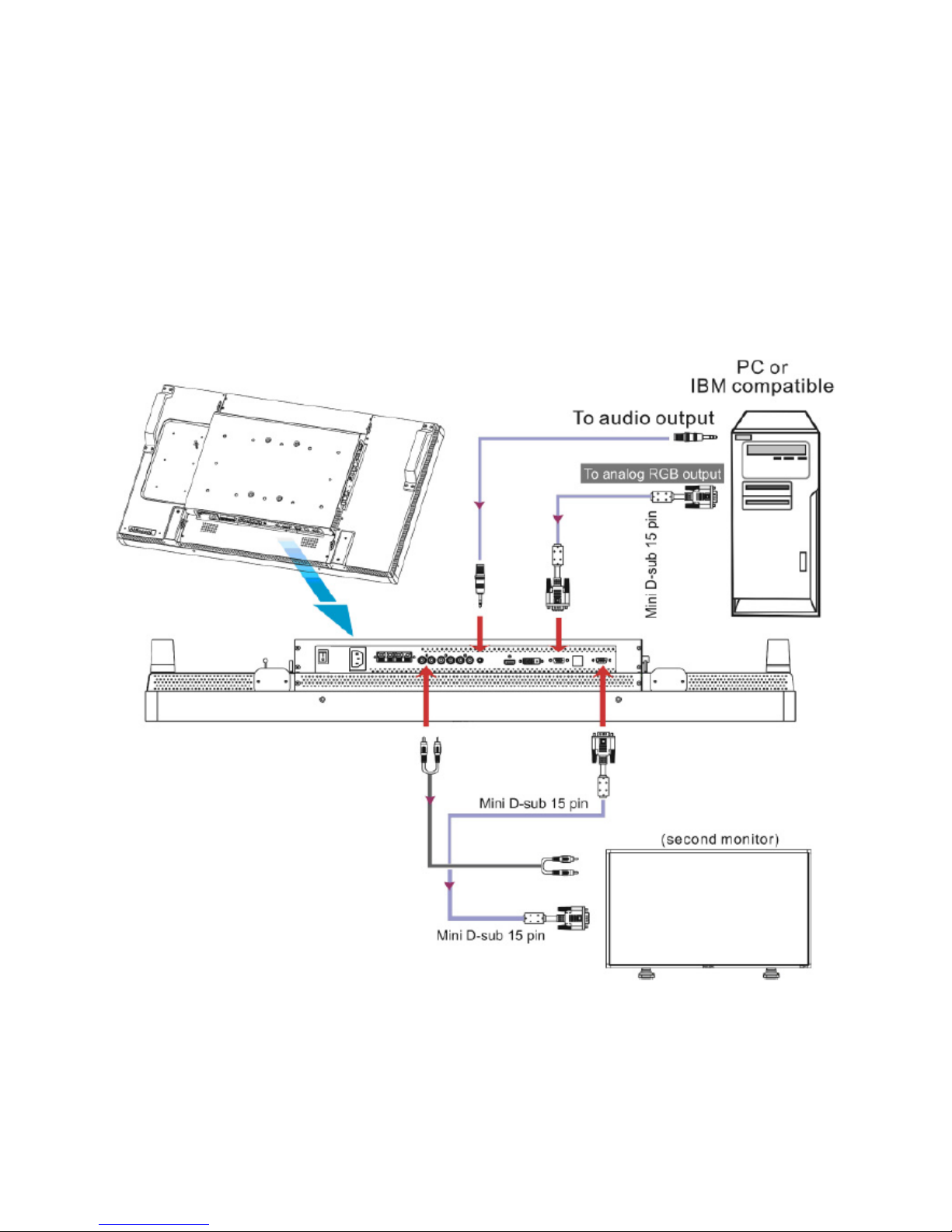
Connecting to a Personal Computer
As you finish the connection between the computer and the LCD monitor, you could play the contents in the computer and display them
on the LCD monitor.
Connecting the LCD Monitor to a Personal Computer
• To achieve this, apply the supplied VGA signal cable (mini D-sub 15 pin to mini D-sub 15 pin) to make connection between a PC and
the LCD monitor (VGA IN connector).
• When connecting more than one LCD monitors to a PC, apply another VGA signal cable (mini D-sub 15 pin to mini D-sub 15 pin; it’s
commercially available) to make connection between the LCD monitor(VGA OUT connector) and the other (VGA IN connector).
• The AUDIO IN 1, 2, 3 or HDMI can be connected for audio input. After choosing one of the AUDIO IN connectors, you might need to
select AUDIO 1, 2, 3 or HDMI using the AUDIO SOURCE button on the remote control.
• When connecting more than one LCD monitors to a PC, apply RCA cable to make connection between the LCD monitor(AUDIO OUT
connector) and the other (AUDIO IN 1, 2, 3). HDMI source is not suitable for this case.
ViewSonic CD4233
20
Page 23
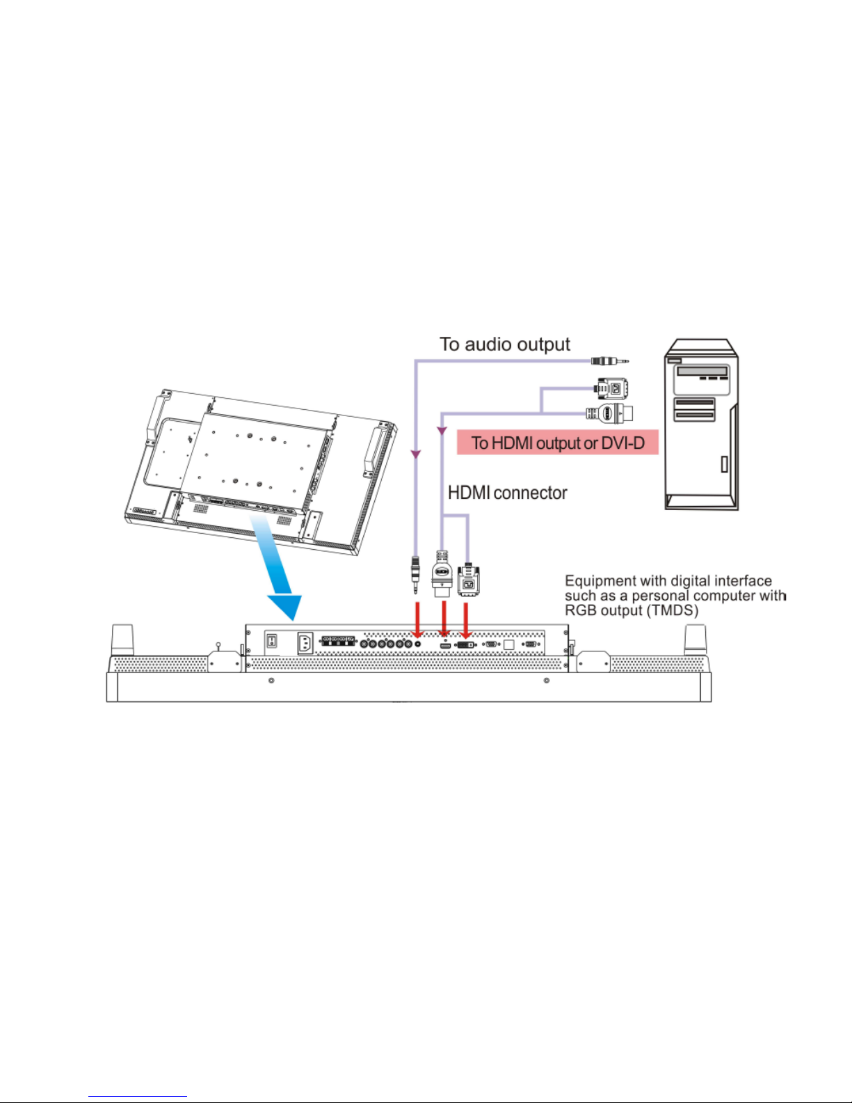
Connecting to a Digital Interface Equipment
Connections can be made between the LCD monitor and other digital equipment that is equipped with a digital interface compliant with
the DVI (Digital Visual Interface) standard.
Connect the LCD Monitor to a Computer with a Digital Output
• The HDMI , DVI-D IN connector accepts a HDMI cable.
• HDMI and DVI-D can receive HDMI video signals from either a HDMI output of for instance a DVD player or from a DVI-D output of a
PC.
• To ensure the display quality, use a cable with a quality prescribed by DVI standards.
• The AUDIO IN 1, 2, 3 or HDMI connector can be chosen to receive an audio source. Select AUDIO 1, 2, 3 or HDMI from the AUDIO
SOURCE button on the remote control. HDMI(for audio) is only selectable only when HDMI or DVI-D (for video) is selected.
• Note that the signal of a HDMI / DVI-D connector cannot be output to the VGA OUT connector.
ViewSonic CD4233
21
Page 24
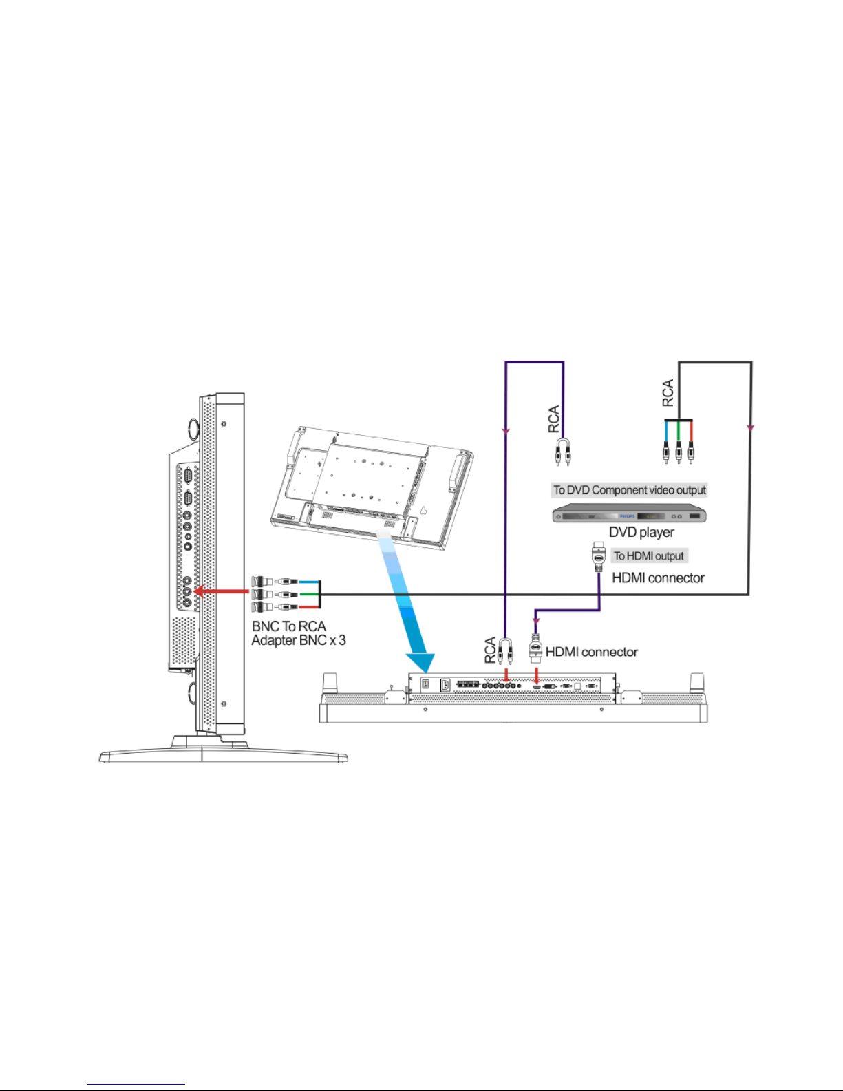
Connecting to a DVD Player
As you finish the connection between the DVD player and the LCD monitor, you could display the contents from the played DVD on the
LCD monitor. You might like to refer to your DVD player’s manual for further information.
Connect the LCD Monitor to a DVD Player
• To achieve this, apply a 3x components cable (Y, Pb, Pr) with BNC connectors at one end and RCA connectors at the other end
between DVD player and display. In case you can only obtain RCA connectors on both ends you can use the in box available BNCto-RCA converters.
DVD player(Y, Pb, Pr Out) and LCD monitor (COMPONENT). You might need BNC-to-RCA adapters(including in the accessories) to
convert the BNC connectors to RCA connectors if you are using the separated signaling(Y, Pb, Pr) RCA cable.
• If your DVD player supports HDMI signaling, apply a HDMI to HDMI cable for the connection.
• The AUDIO IN 2 , 3 (both of RCA connector type) can be used for audio input. Select [AUDIO 1] (for 3.5ij phone jack), [AUDIO 2],
[AUDIO 3] Or [HDMI] from the AUDIO SOURCE button on the remote control. HDMI (for audio) is selectable only when HDMI or DVID (for video) is selected.
ViewSonic CD4233
22
Page 25
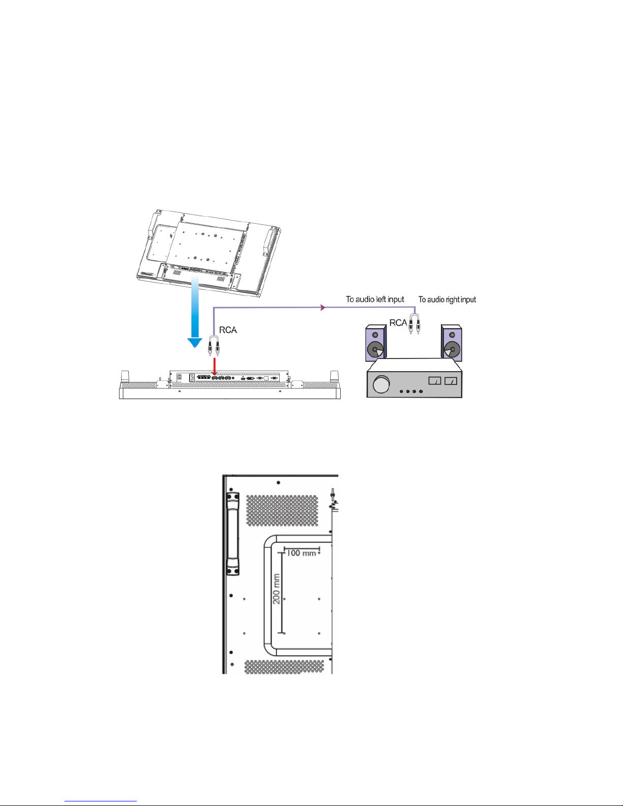
Connecting to a Stereo Amplifier
You can connect your stereo amplifier to your LCD monitor. Refer to your amplifier's manual for further information.
Connect the LCD Monitor to a Stereo Amplifier
• Turn on the LCD monitor and the amplifier only after all connections have been finished.
• Apply 2 RCA cables (audio left and right) to make connection between the amplifier (audio in) and the LCD monitor (audio out).
• Do not reverse the audio left and right jacks.
• For the preferred audio signal, select [AUIDO1], [AUDIO2], [AUDIO3] or [HDMI] from the AUDIO SOURCE button on the remote control.
HDMI(for audio) is selectable only when HDMI or DVI-D (for video) is selected.
• The AUDIO OUT RCA connectors output sound from the selected AUDIO SOURCE.
Connecting to a display mounted PC
This monitor has an area in the backcover to mount a small form fact PC or set-top box.
You can connect your mounted PC to your LCD monitor. Use M4 mounting screws for 100x200 mm to fix your mount PC.
ViewSonic CD4233
23
Page 26
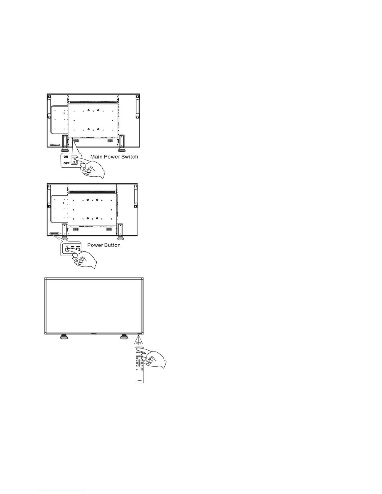
Basic Operation
Power ON and OFF Modes
The LCD monitor power indicator will turn green while powered on and will turn red while powered off. The monitor can be powered on
or off using the following three options:
1. Pressing the Main Power Switch.
NOTE:
When the Main Power Switch is used to power off the LCD monitor,
the remote control, the power button and the indicator will not work.
Make sure to turn the Main Power Switch on before using the
other two options.
2. Pressing the power button.
NOTE:
Before pressing the power button, be sure to turn on the Main
Power button on the LCD monitor.
3. Using the remote control.
NOTE:
Before operating the remote control, be sure to turn on the Main
Power Switch on the LCD monitor.
ViewSonic CD4233
24
Page 27
Power Indicator
Status
Power ON Green
Power Standby Red
Power OFF LED Off
Diagnosis
(Detecting failure)
Red Blinking
* See troubleshooting
Using Power Management
Please turn off the LCD monitor when it will not be used for long time. This could potentially increase the life and decrease the power
consumption of the LCD monitor.
Standby mode: Push the power button on the remote control or on the monitor to enter the standby mode.
Power Off: Push the Main Power Switch to enter the power off mode.
Display Signal of Video Source Setting to [VIDEO]
Use the input button on the front panel or the VIDEO SOURCE button on the remote control to set video source to [VIDEO].
Use the COLOR SYSTEM OSD menu to select [AUTO], [NTSC], [PAL], [SECAM], [PAL60], [4.43NTSC], according to your video format.
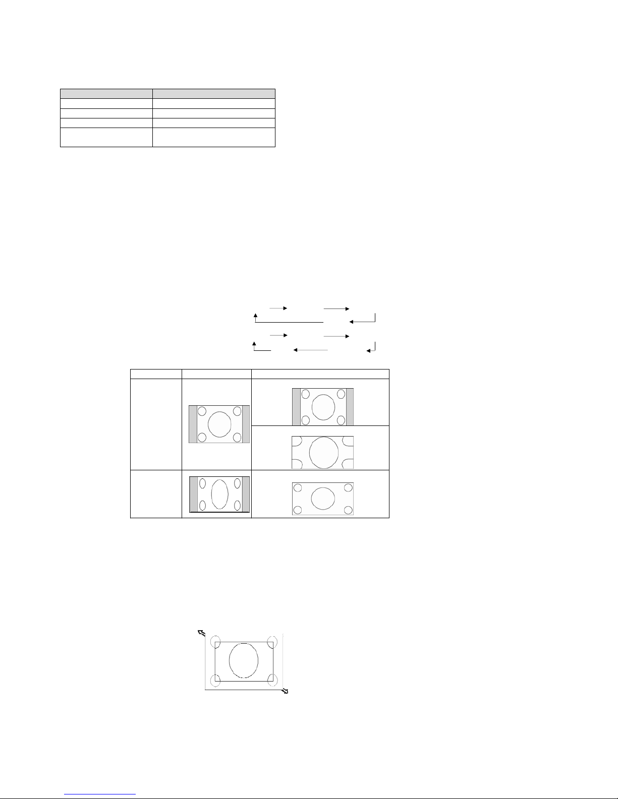
Picture Size
HDMI, DVI-D, VGA FULL NORMAL CUSTOM
REAL
COMPONENT, VIDEO FULL NORMAL DYNAMIC
REAL CUSTOM
Sign
al Type NORMAL SIZE Recommended Size
NORMAL
4:3
DYNAMIC
Squeeze
FULL
NORMAL: Display with the input signal aspect ratio from PC signal, or display in 4:3 aspect ratio at COMPONENT or VIDEO signal.
FULL: Display in the entire screen.
DYNAMIC: Expand 4:3 pictures to the entire screen with non-linearity. (Some round image might be cut by expansion.)
CUSTOM (ZOOM): Images can be expanded beyond the active display area. The image which is outside of the active display area would
not be shown.
REAL: Image will be displayed for one by one pixel.
ZOOM
ZOOM
ViewSonic CD4233
25
Page 28
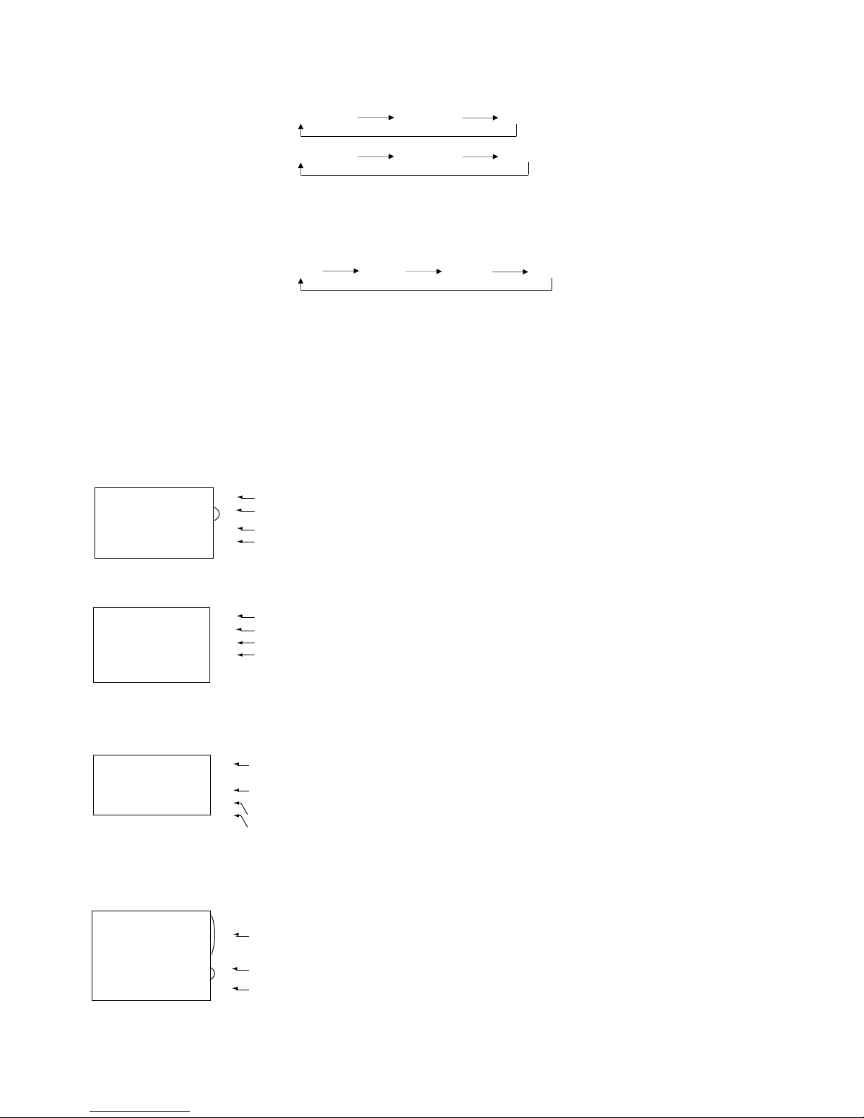
Smart Picture Mode
HDMI, VGA HIGHBRIGTH STANDARD sRGB
COMPONENT, VIDEO HIGHBRIGTH STANDARD CINEMA
Audio Source Switching
You can select the audio source using the AUDIO SOURCE button on the remote control.
HDMI
HDMI AUDIO1 AUDIO2 AUDIO3
Control Lock Mode
This function disables the operation o buttons so that the adjustments you make are not active when they are pressed.
To disable the buttons, press and hold down the S and T buttons together for at least 3 seconds.
To enable the buttons, press and hold down the S and T buttons together for at least 3 seconds again.
OSD Information
HDMI, VGA
VGA
Video Source
1024 x 768
Input signal Information
48kHz 60Hz
Audio Source
AUDIO : 1
Picture Size
SIZE : FULL
COMPONENT
COMPONENT
Video Source
1080P
Input signal Information
AUDIO :
2
Audio Source
SIZE : FULL
Picture Size
S-VIDEO, VIDEO
S-VIDEO
Video Source
NTSC
AUDIO :3
Color System of Input Signal
SIZE : NORMAL
Audio Source
Picture Size
PIP or POP
Main:VGA
Sub:S-VIDEO
VGA
1024 x 768
Main picture Information
48kHz 60Hz
AUDIO : 1
S-VIDEO
Sub picture Information
NTSC
Main
picture
Information
SIZE : FULL
ViewSonic CD4233
26
Page 29
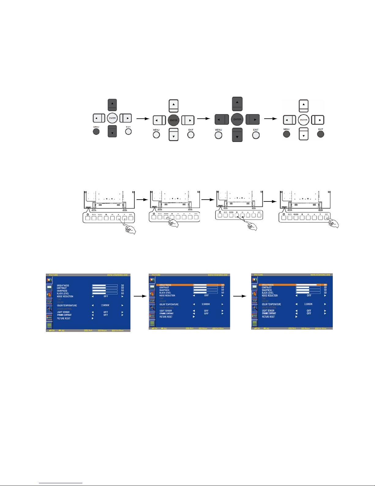
OSD (On-Screen-Display) Controls
Press UP or DOWN, and LEFT
or RIGHT button to select
function, or adjust the setting.
Press ENTER button to enable
the setting.
Pr
ess MENU button to
open Main menu.
Press UP or DOWN
button to select submenu.
Pr
ess ENTER button Press MENU or
to enable setting. EXIT button to exit.
Remote Control
Control Panel
Press EXIT button to
open Main menu. Press
UP or DOWN button to
select.
Press SOURCE button
to enable the setting.
Press EXIT button to exit.
Press UP or DOWN, and LEFT
or RIGHT button to select
function, or adjust the setting.
Press ENTER button to enable
the setting.
UP or DOWN button SOURCE button “+” “-” button EXIT button
OSD screen
ViewSonic CD4233
27
Page 30
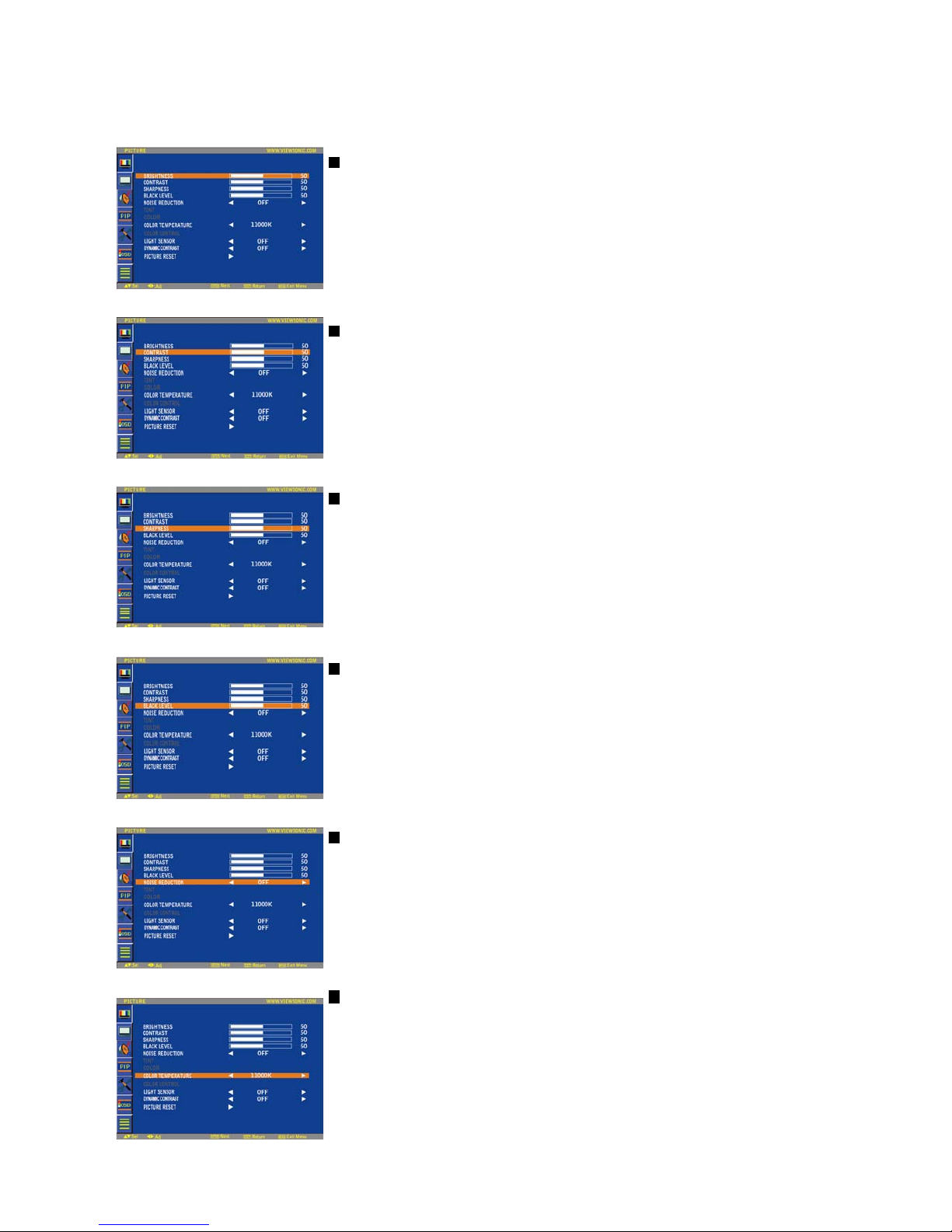
Main-Menu
PICTURE
BRIGHTNESS
Adjusts the overall image and background screen brightness.
Press ُ button to increase brightness.
Press ٙ button to decrease brightness.
CONTRAST
Adjusts the image brightness for the input signal.
Press ُ button to increase contrast.
Press ٙ button to decrease contrast.
SHARPNESS
This function is digitally capable to keep crisp images at any timing.
It is adjustable to get a distinct image or a soft one as you prefer and set independently for each
picture mode.
Press ُ button to increase sharpness.
Press ٙ button to decrease sharpness.
BLACK LEVEL
Adjusts the image brightness for the background.
Press ُ button to increase black level.
Press ٙ button to decrease black level.
NOTE: sRGB picture mode is standard and cannot be changed.
NOISE REDUCTION
Adjusts the noise reduction level.
Press ُ button to increase reduction level.
Press ٙ button to decrease reduction level.
COLOR TEMPERAT U RE
Is used to adjust the color temperature.
The image becomes reddish as the color temperature decreases, and becomes bluish as the color
temperature increases.
ViewSonic CD4233
28
Page 31
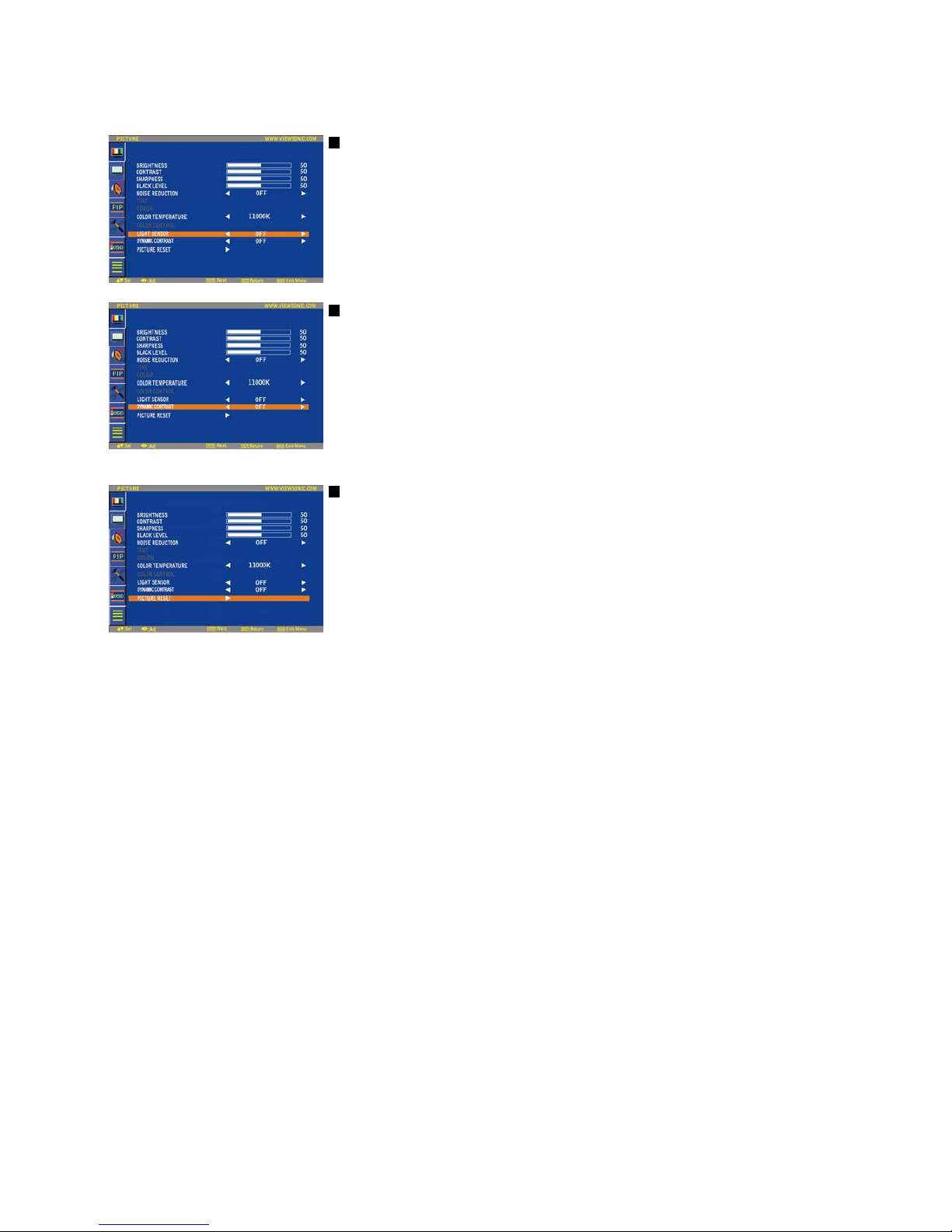
LIGHT SENSOR
Select “ON” to enable the ambient light sensor. The image brightness will be auto adjusted
when ambient light changed.
DYN
AMIC CONTRAST
Select “ON” to enable the dynamic conctrast mode. Can enhancement the image of high
contrast ratio.
PICTURE RESET
Selecting Picture reset allows you to reset all OSD settings about PICTURE setting.
Select “Yes” and press “ENTER” button to restore to factory preset data.
Press “EXIT” button to cancel and then return to the previous menu.
ViewSonic CD4233
29
Page 32
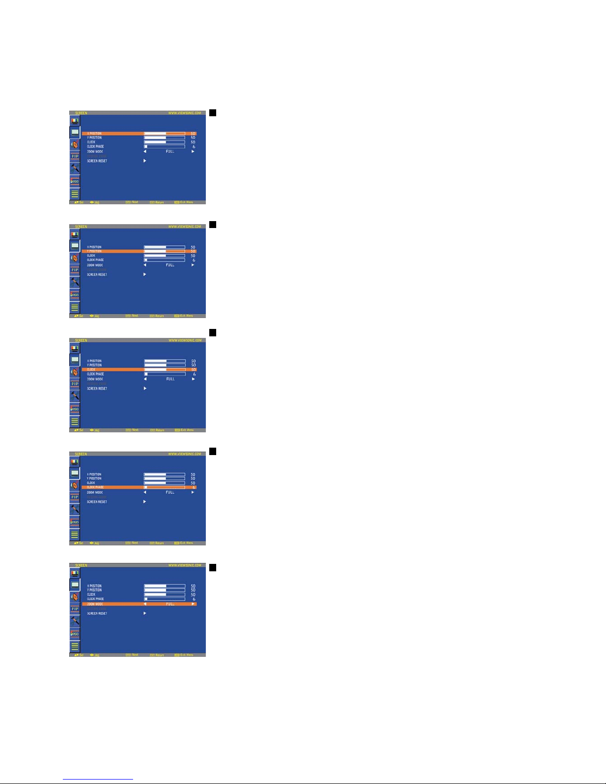
Main-Menu
SCREEN
H POSITION
Controls Horizontal Image position within the display area of the LCD.
Press ُ button to move screen to right.
Press ٙ button to move screen to left.
V POSITION
Controls Vertical Image position within the display area of the LCD.
Press ُ button to move screen to UP.
Press ٙ button to move screen to DOWN.
CLOCK * : INPUT VGA only
Press ُ button to expand the width of the image on the screen the right.
Press ٙ button to narrow the width of the image on the screen the left.
CLOCK PHASE
* : INPUT VGA only
Improves focus, clarity and image stability by increasing or decreasing this setting.
ZOOM MODE
You can select “FULL”, “NORMAL” and “CUSTOM” and “REAL”. (INPUT HDMI,DVI-D,VGA only)
You can also select “FULL”,“NORMAL” “DYNAMIC” and “CUSTOM” and “REAL”. (INPUT
COMPONENT, S-VIDEO, VIDEO only)
Selecting “DYNAMIC” will make the screen display panoramic with the expansion of the middle and
outside of the screen changed. (The upper and the bottom of the image will be cut by expansion.)
Dynamic image is the same as FULL size image when HDTV signal is input.
Selecting “REAL” image will be displayed 1 by 1 pixel.
ViewSonic CD4233
30
Page 33

SCREEN RESET
Selecting Screen reset allows you to reset all OSD settings from PICTURE setting.
Select “Yes” and press “ENTER” button to restore the factory preset data.
Press “EXIT” button to cancel and then return to the previous menu.
ViewSonic CD4233
31
Page 34
Main-Menu
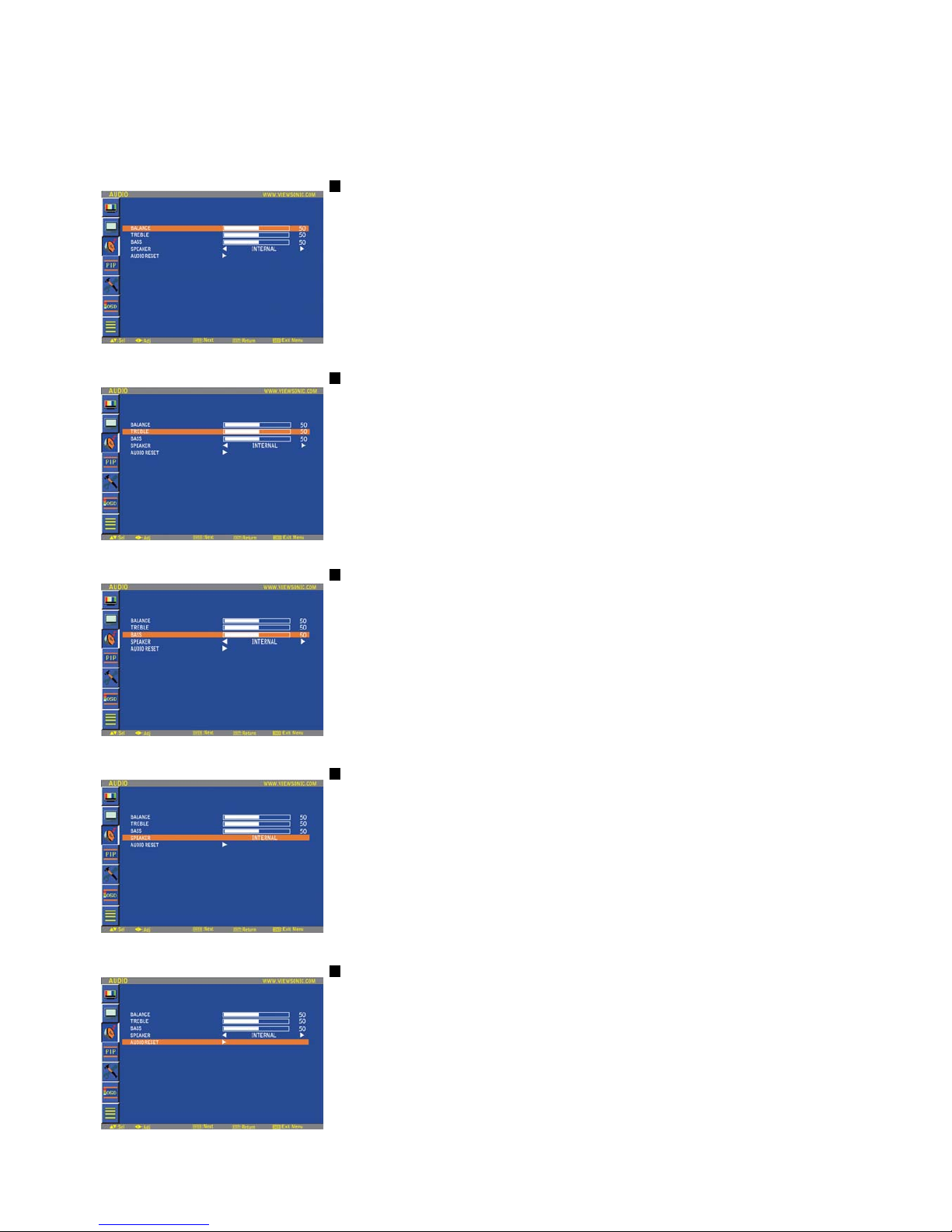
AUDIO
BALANCE
Adjusts the balance of L/R volume.
Press ُ button to move the stereo sound image to right.
Sound of the left side will be small.
Press ٙ button to move the stereo sound image to left.
TREBLE
This feature helps you to accentuate or reduce the high frequency sound.
Press ُ button to increase TREBLE sound.
Press ٙ button to decrease TREBLE sound.
BASS
This feature helps you to accentuate or reduce the low frequency sound.
Press ُ button to increase BASS sound.
Press ٙ button to decrease BASS sound.
SPEAKER
This feature helps you to cut the internal or the external loudspeaker.
Press ُ or ٙ button to exchanges the internal and the external loudspeaker.
AUDIO RESET
Selecting Audio reset allows you to reset all OSD settings from AUDIO setting.
Select “YES” and press “ENTER” button to restore the factory preset.
Press “EXIT” button to cancel and then return to the previous menu.
ViewSonic CD4233
32
Page 35
Main-Menu
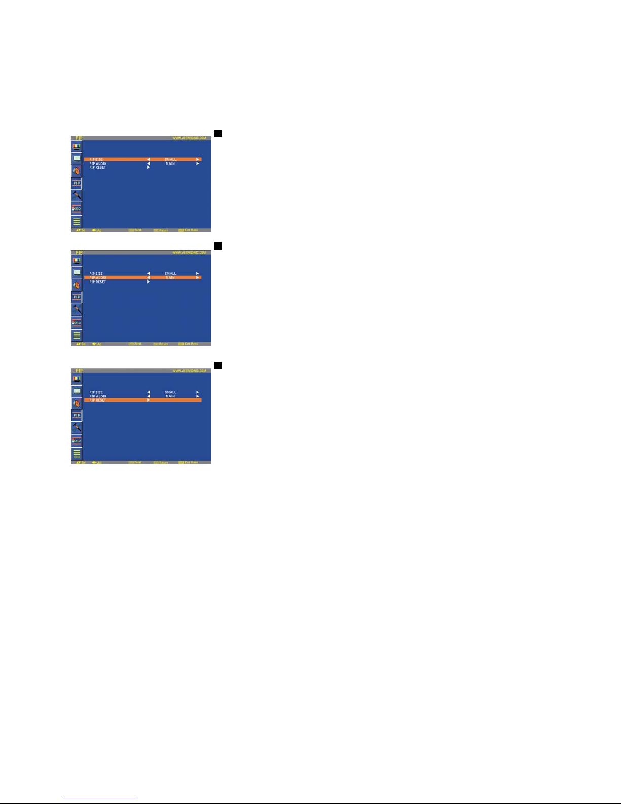
PIP (PICTURE IN PICTURE)
Note: The “PIP” and “POP” modes do not function when the screen size is “CUSTOM” or “REAL”.
PIP SIZE
Selecting the size of picture inserted at the “Picture-in-Picture” (PIP) mode.
“Large”, “Middle” and “Small” are available.
PIP AUDIO
Selecting the sound source in PIP mode.
When selecting “MAIN AUDIO”, you will get the sound for the main picture and when selecting
“PIP AUDIO”, you will get the sound for the picture instead.
PIP RESET
Selecting PIP Reset allows you to reset all OSD settings from PIP setting.
Select “Yes” and press “ENTER” button to restore the factory preset data.
Press “EXIT” button to cancel and then return to the previous menu.
ViewSonic CD4233
33
Page 36
Main-Menu
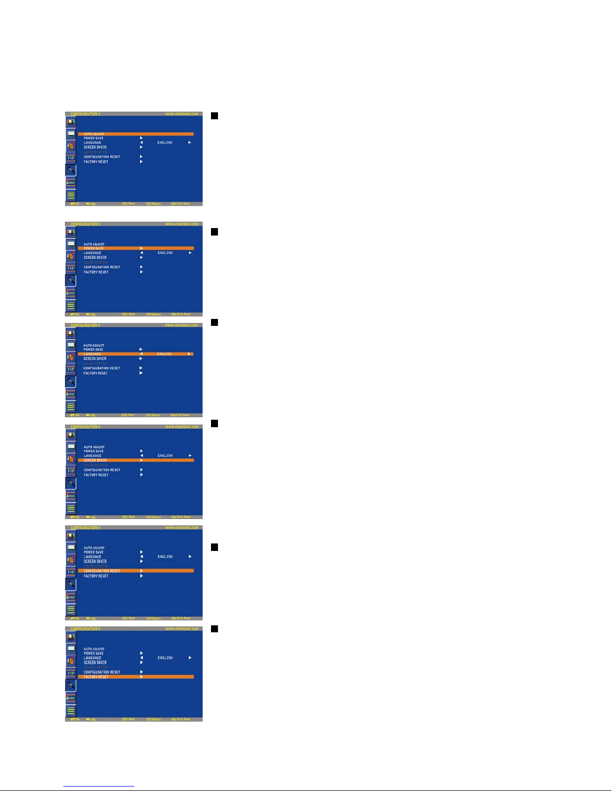
CONFIGURATION 1
AUTO ADJUST * : INPUT VGA only
Press "ENTER" button to automatically adjust screen size, horizontal position, vertical position,
clock,
clock phase, white level and black level.
Press " EXIT " button to cancel execution AUTO ADJUST and then will return to the previous
menu.
POWER SAVE
Selecting RGB "ON", the monitor will go to power management mode when HDMI, DVI-D,VGA,
sync is lost.
Selecting VIDEO "ON", the monitor will go to power management mode after about 10 minutes
delay from when COMPONENT and VIDEO input signal is lost.
LANGUAGE
OSD control menus are available in eight languages.
(English, German, French, Italian, Spanish, Polish, Turkish, Russian, Simple Chinese)
SCREEN SAVER
Select "SCREEN SAVER" functions to reduce the risk of the "image persistence".
COOLING FAN: The cooling fan will be auto-turned on and off according to temperature of
monitor when selected “AUTO”. The cooling fan will be turned on always when selected “ON”.
BRIGHTNESS: The brightness is decreased when selected "
High, Middel and Low ".
PIXEL MOTION: Image is slightly expanded and moves 4 directions (UP, DOWN, RIGHT, LEFT)
periodically
(Need setting the time for movement).
Movement area is approximately +/- 5pixel from original position;
Please locate the important information such as text within 90% area of screen image.
See note (1) for this functions.
PIP will be disabled when "MOTION" is active.
CONFIGURATION RESET
Selecting the CONFIGURATION RESET allows you to reset all configuration settings.
Select "Yes" and press "ENTER" button to restore the factory preset data.
Press " EXIT " button to cancel and return the previous menu.
FACTORY RESET
Selecting "YES" allows you to reset PICTURE, SCREEN, AUDIO, CONFIGURATION1,2 and
ADVANCED OPTION will be back to factory settings (except LANGUAGE, DATE AND TIME and
SCHEDULE).
Select "YES" and press "ENTER" button to restore the factory preset data. Press " EXIT "
button to cancel and return the previous menu.
ViewSonic CD4233
34
Page 37
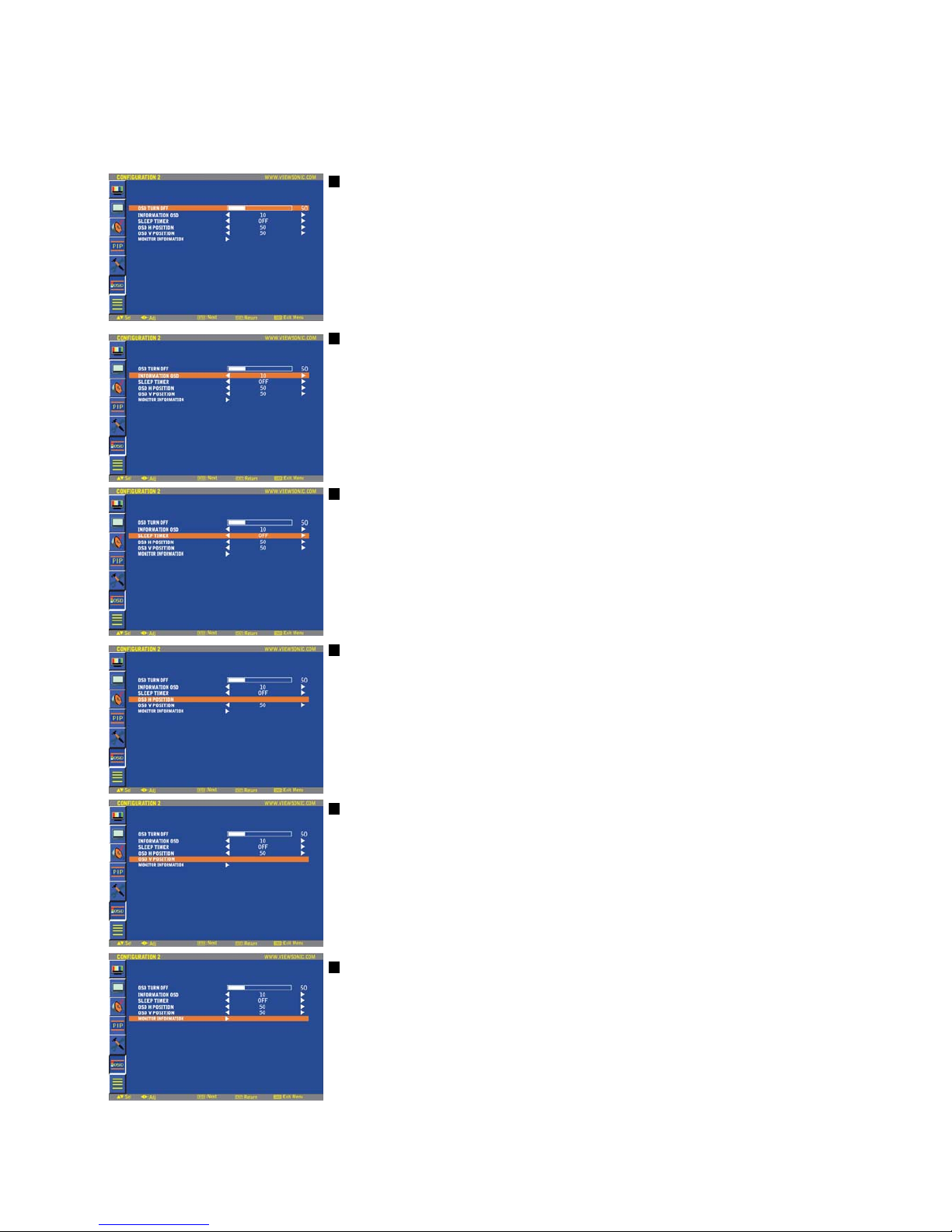
Main-Menu
CONFIGURATION 2
OSD TURN OFF
The OSD control menu will stay on as long as it is used. In the OSD Turn Off submenu, you can
select how long the monitor waits after the last touch of a button to shut off the OSD control menu.
The preset choices are 5 -120 seconds.
INFORMATION OSD
Selects the information OSD to be displayed or not.
The information OSD will be displayed when the input signal is changed or a source change or
warning message like no-signal or out-of range.
A time between 1 to 10 seconds is available.
SLEEP TIMER
To select SLEEP TIMER mode ON/OFF.
In the SLEEP TIMER menu, you can preset the monitor to automatically power down.
A time between 1 to 24 hours is available.
When the SLEEP TIMER is set, the SCHEDULE settings will be disabled.
OSD H POSITION
Adjusts the horizontal position of the OSD menu.
OSD V POSITION
Adjusts the vertical position of the OSD menu.
MONITOR INFORMATION
Indicates the model and serial number of your monitor.
ViewSonic CD4233
35
Page 38
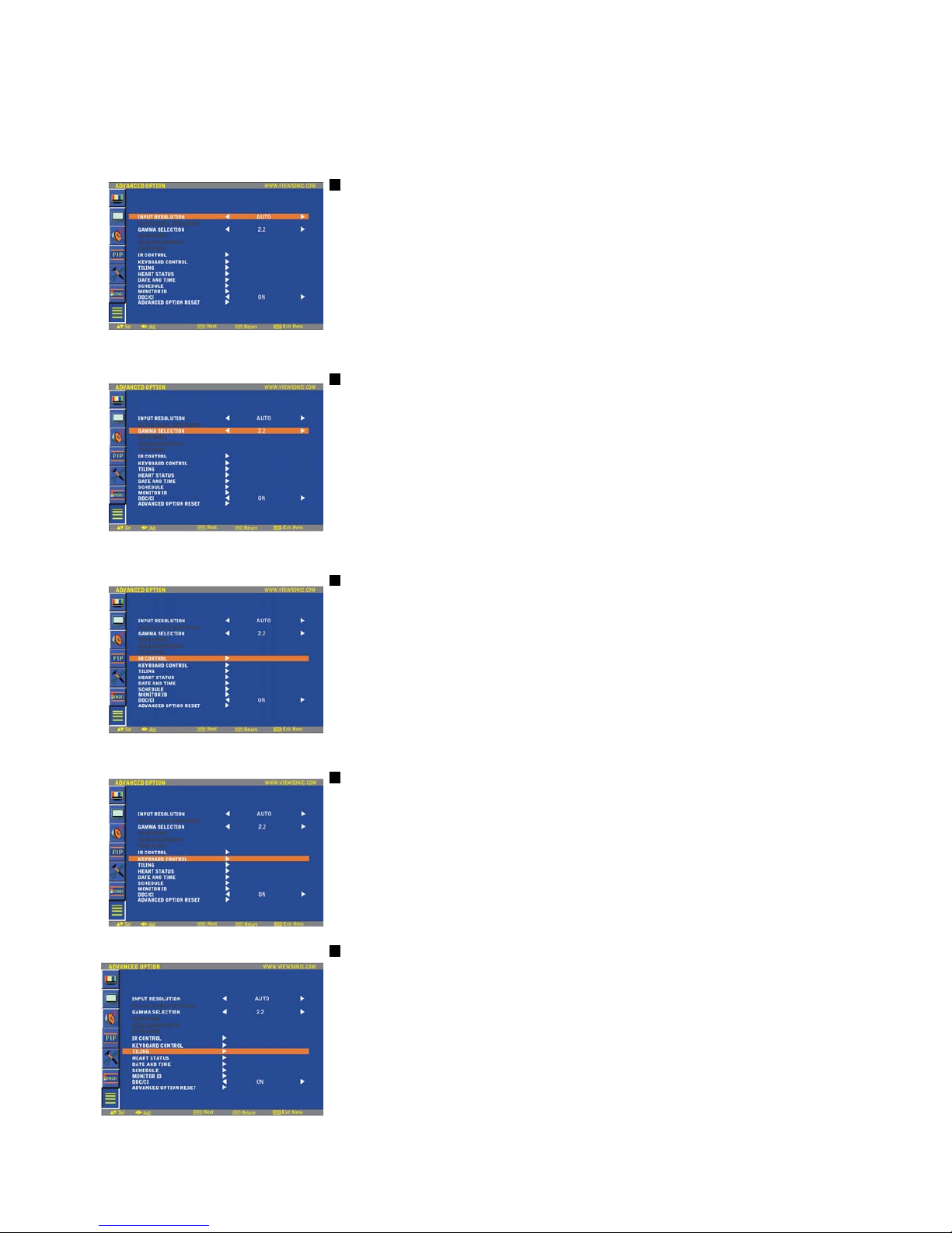
Main-Menu
ADVANCED OPTION
INPUT RESOLUTION * : INPUT VGA only
This feature makes the display controlling the source in order to match display capabilities by
choice or automatically. You can select one of the following timings:
(1)1024x768, 1280x768, 1360x768 and 1366x768.
(2) 640x480, 720x480 and 852x480
(3) 800x600, 1064x600 and 720x576
(4) 1400x1050 and 1864x1050
(5) 720x400 and 640x400
AUTO: Determines the resolution automatically.
The setting you select becomes effective when POWER is turned OFF and ON again.
GAMMA SELECTION
Selects a display gamma. It refers to the brightness performance curve of signal input.
2.2
2.4
S gamma
Native
NOTE: sRGB picture mode is standard and cannot be changed.
IR CONTROL
Selects the operation mode of the remote controller when multiple monitors are connected via
RS232C.
The item in this menu will become effective by pressing “ENTER” button on the selected item.
NORMAL: The monitor will be controlled normally by remote controller.
PRIMARY: The first monitor of those multi-connected via RS232C is designated as PRIMARY.
SECONDARY: monitors other than the first one multi-connected via RS232C are designated as
SECONDARY.
LOCK: Disable the monitor control by infrared remote controller.
Keep pressing “DISPLAY” button during 5 sec or more, this setting will return to “NORMAL”.
KEYBOARD CONTROL
Selects the operation mode of the keyboard control.
Select “LOCK” to disable the keyboard.
Select “UNLOCK” to enable the keyboard.
TILING
TILING demonstrates multiple screens. This feature provides a single large screen using up to 25
monitors.
It will be able to divide up to 5 each H and V.
This requires you to feed the PC output into each of the monitors through a distributor.
H MONITORS: Select number of horizontal monitors.
V MONITORS: Select number of vertical monitors.
POSITION: Select a position to expand the screen.
FRAME COMP: Works in tandem with TILING to compensate for the width of the tile bezels in
order to accurately display the image.
ENABLE: Select “YES”, the monitor will expand the selected position.
PIP and STILL will be disabled when “TILING” is activated.
ViewSonic CD4233
36
Page 39
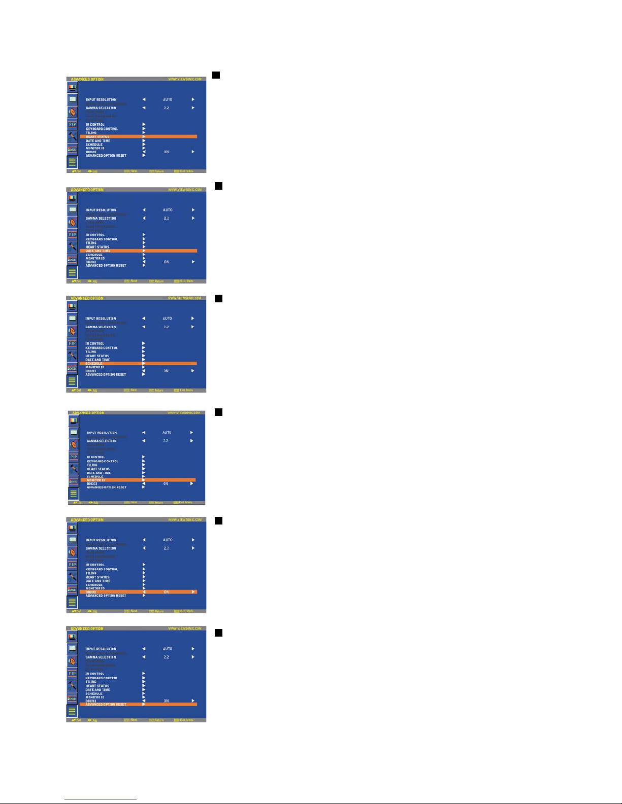
HEAT STATUS * : Disclamer: Heat sensor is indicative.
HEAT STATUS allows you to watch the thermal status at any time via the OSD menu and/or via
RS232C commands. The indicated temperature has a accuracy of 3 degrees (plus and minus).
Press “ENTER” button to enter the submenu to monitor the heat status.
Press “EXIT” button to cancel and then return the previous menu.
DATE AND TIME
Adjusts the current date and time for internal clock.
You should set this function when you use “SCHEDULE”.
SCHEDULE
Programs the monitor's working schedule.
Schedules the power on and power off by using hour and a day of the week. Also sets the input
port.
This OSD can't be removed except EXIT.
MONITOR ID
ID numbers for remote control are assigned to monitors that are multi-connected via RS232C.
ID numbers 1 to 26 are selectable.
DDC/CI
Use to turn ON or OFF the DDC/CI communication function. Select ON for normal use.
ADVANCED OPTION RESET
Selecting ADVANCED OPTION RESET allows you to reset all OSD settings from ADVANCED
OPTION settings, except for GAMMA SELECTION, DATE AND TIME, SCHEDULE, HDMI
INPUT MODE, DVI-D INPUT MODE,MONITOR ID, and DDC/CI.
Select “YES” and press “ENTER” button to restore the factory preset data.
Press “EXIT” button to cancel and then return the previous menu.
GAMMA SELECTION is reset when carrying out the PICTURE RESET in the PICTURE.
ViewSonic CD4233
37
Page 40

NOTE
NOTE 1: IMAGE PERSISTENCE
Please be aware that LCD Technology may experience a phenomena known as Image Persistence. Image Persistence occurs when
residual or “ghost” image of a previous image remains visible on the screen. Unlike CRT monitors, LCD monitors’
image persistence is not permanent, but constant images being displayed for a long period of time should be avoided.
To alleviate image persistence, turn off the monitor for as long as the previous image was displayed. For example, if an
image was on the monitor for one hour and a residual image remains, the monitor should be turned off for one hour to erase the image.
As with all personal display devices, ViewSnoic recommends displaying moving images and using a moving panel saving at regular
intervals whenever the screen is idle or turning off the monitor when not in use.
Please set “POWER SAVE”, “SCREEN SAVER”, “DATE AND TIME” and “SCHEDULE” functions to further reduce the risk of
Image persistence.
For long life use of Public Display
< Image Sticking of LCD Panel >
When LCD panel is operated continuously for long hours, a trace of electric charge remains near the electrode inside LCD, and residual
or “ghost” image of previous image may be observed. (Image Persistence)
Image Persistence is not permanent, but when fixed image is displayed for long period, ionic impurities inside LCD are accumulated
along the displayed image, and it is observed permanently. (Image Sticking)
< Recommendations >
For preventing the fast transition to Image Sticking, and for longer life usage of LCD, following are recommended.
1. Static images should not be displayed for long period. Always use a short cycle to change to other images.
2. In case a fixed image is displayed for a long period, it is
advised to activate the MOTION feature that will periodically move the image in
four directions
3. When not in use, please turn off the monitor with your remote control, or use Power Management Function or use the Schedule
Function of monitor.
4. Reducing the environmental temperature will increase the life of your monitor.
When Protection board (glass, acryl) is installed over the LCD surface, enclosed into the box / wall, or stack the monitor, please utilize
the temperature sensors inside monitor.
To reduce the environmental temperature, the monitor should be set Low Brightness or Cooling Fan “ON” by using Screen sever Function.
5. Please use "SCREEN SAVER Mode" of monitor.
NOTE 2: HOW TO SETUP SCHEDULE
Using the “SCHEDULE” function allows you to set up to seven different scheduled time intervals when the LCD Monitor will be
activated.
You can select the time the monitor turns on and turns off, the day of week the monitor is activated, and which input source the
monitor will use for each scheduled activation period. A check mark in the box next to the number of the schedule indicates that the
selected schedule is in effect.
To select which schedule to set, use the up/down arrows to move the number (1 to 7) of the schedule.
Use the (ُ) and (ٙ) buttons to move the cursor horizontally within the particular schedule. Use the ( ) and ( ) buttons to increase time
and select input port. The “ENTER” button is used to make a selection.
If you create a schedule but do not want to use a power on time, select “--” in the “ON” time slot.
If you do not want to use a power off time select “--” in the OFF time slot.
If there is no input selected (“--” showing in the input spot) the input from the previous schedule will be used.
The selection of EVERY DAY within a schedule takes priority over other schedules that are set up to operate weekly. When schedules
are overlapping, scheduled Power ON time has priority over scheduled Power OFF time.
If there are two schedules programmed for the same time, then the highest numbered schedule has priority. When the “SLEEP
TIMER” is set, the “SCHEDULE” function is disabled.
ViewSonic CD4233
38
Page 41
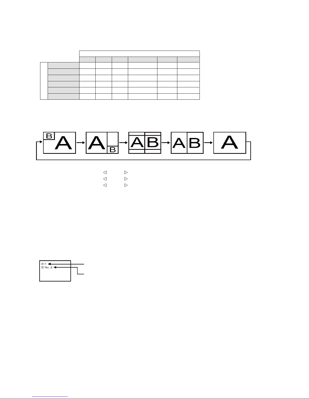
NOTE 3: “PIP”, “POP” and “SIDE BY SIDE”
The following table shows the combination of signal inputs under which the “PIP” and “POP” modes function. These modes do not
function, however, when the screen size is “CUSTOM” or “REAL”.
SUB
HDMI DVI-D VGA COMPONENT S-VIDEO VIDEO
HDMI
±
±± ±
{{
DVI-D
±
±± ±
{{
{: Supported
VGA
±
±± ±
{{
±: Not supported
COMPONENT
±
±± ±
{{
S-VIDEO
{
{{ {
±±
MAIN
VIDEO
{
{{ {
±±
Press the “PIP ON/OFF” buttons on the remote control to change between “PIP”, “POP” and “SIDE BY
SIDE” mode as shown in the diagram below.
PIP POP
SIDE BY SIDE
ASPECT
SIDE BY SIDE FULL
OFF
“PIP”, “POP” mode resolution (Reference)
PIP SIZE
SMALL
MIDDLE
LARGE
: 450 dots X 338 dots
: 675 dots X 450 dots
: 900 dots X 675 dots
POP SIZE
: 450 dots X 338 dots
< Remote control numbering function >
By connecting multiple monitors using RS232C cables, you can control any one monitor or all the monitors by one remote controller.
1. Assign arbitrary ID number to each of multi-connected monitors using MONITOR ID. ID numbers 1 to 26
are selectable.
It is recommended to assign sequential ID numbers from 1 and up.
2. The remote control mode of the first monitor is set to PRIMARY and those of the other monitors are set to
SECONDARY.
3. When you direct the remote controller at the remote control signal sensor of the PRIMARY monitor and press the DISPLAY
button on the remote controller, the ID selection OSD appears at the upper left of the screen.
ID number of the currently viewed monitor
Select the ID number of the monitor you want to control using the ُ/ٙ button
on the remote controller.
The ID of the monitor you want to control is displayed at the upper left of its screen.
By selecting ALL, you can control all the multi-connected monitors.
4. Direct the remote controller at the remote control signal sensor of the PRIMARY monitor. OSD
appears on the monitor having the ID number you selected.
NOTE:
When the ID selection OSD is being displayed on the PRIMARY monitor, press the DISPLAY button on the remote controller again to
cancel the ID selection OSD and then control the monitor you selected.
HINT:
If you set the remote control mode wrongly and remote control operation becomes unavailable, press MENU button on the control panel of
the monitor to display the OSD screen and change the remote control mode using ADVANCED OPTION. By pressing
and holding down the DISPLAY button on the remote control for 5 seconds or longer, the remote control mode is initialized to
NORMAL.
ViewSonic CD4233
39
Page 42

Features
Full HD LCD display 1920x1080p
This display has a resolution that is referred to as Full HD. The state-of-the-art LCD screen technology has the full high-definition
widescreen resolution of 1080 progressive lines, each with 1920 pixels. This allows the best possible picture quality for HD input
signals with up to 1080 lines. It produces brilliant flicker-free progressive scan pictures with optimum brightness and superb colors.
This vibrant and sharp image will provide you with an enhanced viewing experience.
Slim bezel
A slim bezel design adds a stylish look to a public display to nicely blend in most environments. Furthermore this design is ideal for
tiled matrix video walls.
Zoom function for tiled matrix
The internal zoom function enables easy implementation of a video wall matrix, without the need for expensive external equipment.
Capable of a vidiwall of 25 displays by dividing up to 5 displays each horizontally and vertically.
High brightness
Allows daylight viewing even in large public environments with high ambient light conditions due to its 700 cd/m² high brightness
professional panel.
Network controllability: RS232C
Network controllability allows user to control and adjust monitors remotely through RS232C protocol.
Smart insert
Professional PC's are part of most public signage installations. Quite often they add additional depth to the public display and a lot
of cable clutter. This public display contains a Smart insert in the backcover that will fit many professional small form factor PC's. In
addition it offers provisions for efficient cable management.
SmartPower
The backlight intensity can be controlled and pre-set by the system to reduce the power consumption by up to 50%, which saves
substantially on energy costs.
Advanced anti image sticking
Static images left on-screen for extended periods of time may leave a "ghost image" or image sticking effect on LCD displays.
Although image sticking in LCD displays is not permanent, you want to prevent this to happen, especially in locations where
content is shown 24/7.
Compliant with RoHS standards
Viewsonic designs and produces display products in compliance with strict Restriction of Hazardous Substances (RoHS) standards
that restrict lead and other toxic substances that can harm the environment.
Automatic Long Cable Compensation:
Automatic long cable compensation prevents image quality degradation (color shift and dull signals) caused by long cable lengths.
ViewSonic CD4233
40
Page 43

Troubleshooting
No picture
• The signal cable should be completely connected to the graphics card/computer.
• Front Power Switch and computer power switch should be in the ON position.
• Check to make sure that a supported mode has been selected on the graphics card or system being used.
(Please consult graphics card or system manual to change graphics mode.)
• Check the monitor and your graphics card with respect to compatibility and recommended settings.
• Check the signal cable connector for bent or pushed-in pins.
• If nothing is displayed on the screen when HDCP device is connected, reset the power of the device.
Power Button does not respond
• Unplug the power cord of the monitor from the AC outlet to turn off and reset the monitor.
Image persistence
• Please be aware that LCD Technology may experience a phenomenon known as Image Persistence. Image Persistence occurs when
a residual or “ghost” image of a previous image remains visible on the screen. Unlike CRT monitors, LCD monitors’ image persistence
is not permanent, but constant images being displayed for a long period of time should be avoided. To alleviate image persistence,
turn off the monitor for as long as the previous image was displayed. For example,
if an image was on the monitor for one hour and a residual image remains, the monitor should be turned off for one hour to erase the
image.
NOTE:
As with all personal display devices, VIEWSONIC recommends displaying moving images and using a moving panel saving at regular
intervals whenever the screen is idle or turning off the monitor when not in use.
Image is unstable, unfocused or swimming is apparent
• Signal cable should be completely attached to the computer.
• Use the OSD Image Adjust controls to focus and adjust display by increasing or decreasing the fine adjustment. When the display
mode is changed, the OSD Image Adjust settings may need to be re-adjusted.
• Check the monitor and your graphics with respect to compatibility and recommended signal timings.
• If your text is garbled, change the video mode to non-interlace and use 60 Hz refresh rate.
Image of component signal is greenish
• Check to see if the COMPONENT input connector is selected.
LED on monitor is not lit (no green or red color can be seen)
• Power Switch should be in the ON position and power cord should be connected.
• Make certain the computer is not in a power-saving mode (touch the keyboard or mouse).
RED LED on monitor is blinking
• A certain failure might have occurred, please contact your nearest authorized VIEWSONIC service facility.
Display image is not sized properly
• Use the OSD Image Adjust controls to increase or decrease the coarse adjustment.
• Check to make sure that a supported mode has been selected on the graphics card or system being used.
(Please consult graphics card or system manual to change graphics mode.)
Selected resolution is not displayed properly
• Use OSD Display Mode to enter Information menu and confirm that the appropriate resolution has been selected.
If not, select corresponding option.
ViewSonic CD4233
41
Page 44

No Sound
• Check to see if speaker cable is properly connected.
• Check to see if mute is activated.
• Check to see if volume is set at minimum.
Remote Control does not work
• Check the Remote Control’s batteries status.
• Check if batteries are inserted correctly.
• Check if the Remote Control is pointing at the monitor’s remote sensor.
“SCHEDULE” / “SLEEP TIMER” function is not working properly
• The “SCHEDULE” function will be disabled when the “SLEEP TIMER” is set.
• If the “SLEEP TIMER” function is enabled and the power to the LCD monitor is turned off if the power supply is interrupted
unexpectedly, then the “SLEEP TIMER” will be reset.
Stripe Noise
Either light vertical or horizontal stripes may appear, depending on the specific display pattern. This is no product fault or degradation.
“NO SIGNAL” is displayed on the screen
Image may not be displayed right after HDCP device is connected.
ViewSonic CD4233
42
Page 45
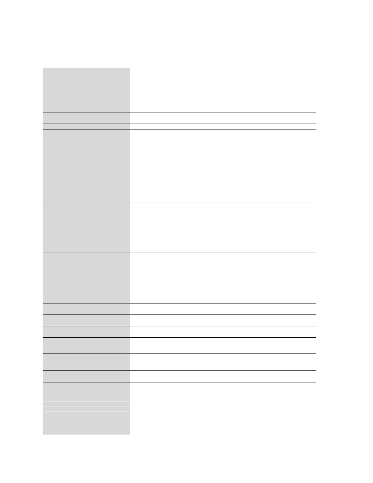
Specifications
Specifications
Product Specifications Analog Input Digital Input
LCD
Module
Diagonal:
Pixel Pitch:
Resolution:
Color:
Brightness:
Contrast
Ratio:
Response
time:
V
iew
Angle:
42"/106.7
cm
0.485
mm
1920x1080
dots
1.07
billion
colors
(depending on video cardused)
700
cd/m2 (typ.)
1,000:1
(typ.) , 3,000:1Dynamic Contrast
9 ms (typ.Gto
G)
Up
and Down 178°,
Left
and Right 178°
(typ.)
@CR>10
Fr
equency Horizontal:
V
ertical:
15.625
/
15.734, 31-91
kHz
50.0/58.0-75.0
Hz
Pixel
Clock
13.5
-165.0
MHz
25.0
-165.0
MHz
V
iewable
Size
930.25 x 523.25mm/
36.6x20.6 inches
Input
Signal
PC-Input:
V
ideo:
Sync:
Input-terminal:
VIDEO
Input:
AUDIO
Input:
RS232C:
In:
Analog RGB
V
ideo: 0.7
Vp-p
TMDS
Input
impedance 75
ohm
SeparateHVsync:
TTL
level (Pos./Neg.),
Input
Impedance 2.2K
ohm
15
Pin
Mini D-sub
HDMI
Composite:
1.0
Vp-p
Input
impedance 75ohm BNC and
RCA-PINJACK-INPUT
Y/CY:1
Vp-p
C: 0.286
Vp-p Input
Impedance 75
ohm
S-TERMINAL-INPUT
Component:
1.0/0.7
Vp-p
Input
Impedance 75
ohm
BNC-INPUT
RCA
PIN-JACK L/R
INPUTx2,
STEREO
Mini Jack
INPUTx1
9
Pin
Mini D-sub
Output
Signal
PC-Output:
V
ideo:
Sync:
Output-terminal:
VIDEO
Output:
AUDIO
Output:
Speaker
Output:
RS232C: Out:
Analog RGBVideo: 0.7
Vp-p
with75ohm
terminated
SeparateHVsync:
TTL
level (Pos./Neg.)
15
Pin
Mini D-sub
BNC-OUTPUTx1,
Composite
1.0
Vp-p
with75ohm
terminated
RCA
PIN-JACK L/R
OUTPUTx1, 0.15Vrms
with
47k
ohm
terminated
Internal Speaker 5W+5W(8
ohm)
External Speaker
Jack7W+7W(8
ohm)
9
Pin
Mini D-sub
Resolutions
Supported
640x480at60
Hz
800x600at60Hz
1024x768at60Hz 1280 x 720 at 60Hz
1280x768at60Hz
1360x768at60Hz
1600x1200at60
Hz
1900x1200 (reduced Blanking only)
1920x1080at60Hz*
*
Recommended Resolution
NTSC,P
AL,SECAM,4.43NTSC,PAL60
DVD:480i,480p,
576i,720p,1080i,1080p
Power Supply 2.4– 1.1 A@100-240VAC,50~60Hz
Power
Consumption
Power
Save:
Typically
232
W
Less than 1W (Power button off or main power switch off.)
Operational
T
emperatur
e:
Envir
onment
Humidity:
Landscape: 5-40 °C/41-104 °F, Portrait : 5-35 °C/41-95
°F
20-80%(Without condensation)
Storage
T
emperatur
e:
Envir
onment
Humidity:
-20-60 °C/-4-140
°F
10-90%
(Without
condensation)/90%-3.5%x(Temp-40°C) r
egar
ding
over
40°C
Dimension Net
without
stand:
Net
with
stand:
Gr
oss:
967.6
mm
(W)x 559.6 mm(H)x 123.1mm(D)/38.09"
(W)
x 22.03"
(H)
x 4.85"
(D)
967.6mm(W)
x605.6 mm
(H)x 405 mm(D)/38.09"
(W)
x23.84"
(H)
x 15.95"
(D)
1170
mm
(W)x 715 mm(H)x 286 mm(D)
/
70.87
"
(W)
x
28.15
"
(H)
x
11.26
"
(D)
W
eight Net
without
stand:
Net
with
stand:
Gr
oss:
48.5lbs/22 kg
52.47 lbs
/
23.8
kg
68.78
lbs
/
31.2
kg
Wall
mounting
interface
8
Holes
(400 mmpitches)
Optional
Multi-purpose
Fix
Mount
Complied
Regulatory
and
Guidelines
UL60950-1/C-UL/EN60950-1/FCC-B/IECS003-B/EN55024/EN61000-3-2/EN61000-3-3
/CE/NOM
Power Management
Support VESA DPMS convention
Plug&Play
VESA
DDC2B,
DDC/CI
Accessories
CD User's
Manual, QSG, Power Cord,VGA
Cable,
,
Remote
Contr
oller,AAA
Batteryx2,
Clamper
x2(Topr
event
from
falling),
Screw
for
Main
switch
coverx6, Screw
for
CLAMPER
x
2, Main
switch
cover.
Note:Technical
specifications
are
subjecttochange
without
notice.
ViewSonic CD4233
43
Page 46
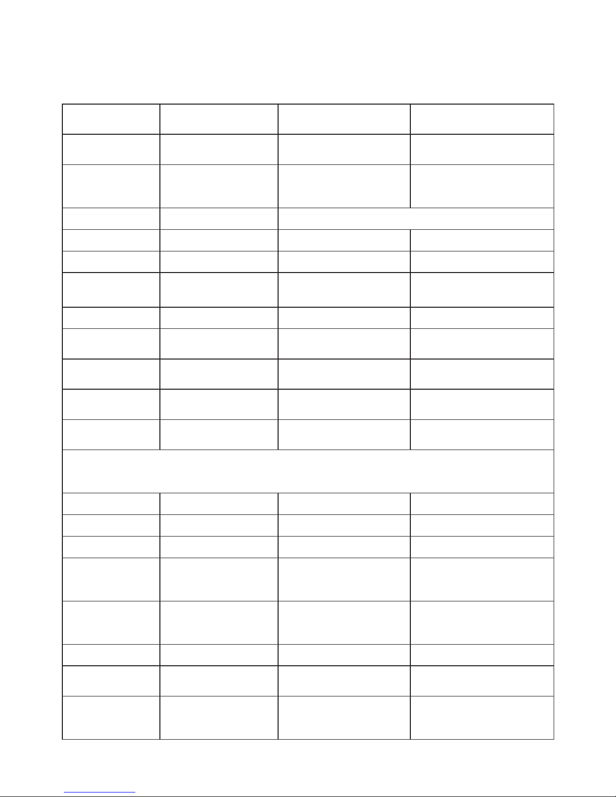
ViewSonic CD4233
Customer Support
For technical support or product service, see the table below or contact your reseller.
Note: You will need the product serial number.
Country/Region Web Site
T=Telephone
F=Fax
E-mail
Australia/New
Zealand
www.viewsonic.com.au
AUS=1800 880 818
NZ=0800 008 822
Canada www.viewsonic.com
T (Toll-Free)= 1-866-463-4775
T (Toll)= 1-424-233-2533
F= 1-909-468-3757
Europe www.viewsoniceurope.com www.viewsoniceurope.com/uk/Support/Calldesk.htm
Ireland (Eire)
www.viewsoniceurope.
com/uk/
www.viewsoniceurope.com/uk/
support/call-desk/
Latin America
(Argentina)
Latin America
(Columbia)
Latin America
(Mexico)
Renta y Datos, 29 SUR 721, COL. LA PAZ, 72160 PUEBLA, PUE. Tel: 01.222.891.55.77 CON 10 LINEAS
Electroser, Av Reforma No. 403Gx39 y 41, 97000 Merida, Yucatan. Tel: 01.999.925.19.16
Other places please refer to http://www.viewsonic.com/la/soporte/index.htm#Mexico
Puerto Rico & Virgin
Islands
www.viewsonic.com
T= 1-800-688-6688 (English)
T= 1-866-379-1304 (Spanish)
F= 1-909-468-3757
Singapore/
Malaysia/
Thailand
United Kingdom
www.viewsoniceurope.
com/uk/
www.viewsoniceurope.com/uk/
support/call-desk/
service_gb@viewsoniceurope.
com
United States www.viewsonic.com
T (Toll-Free)= 1-800-688-6688
T (Toll)= 1-424-233-2530
F= 1-909-468-3757
44
Page 47

ViewSonic CD4233
Limited Warranty
VIEWSONIC LCD Commercial Display
What the warranty covers:
ViewSonic warrants its products to be free from defects in material and workmanship, under normal use, during the
warranty period. If a product proves to be defective in material or workmanship during the warranty period, ViewSonic
will, at its sole option, repair or replace the product with a like product. Replacement product or parts may include
remanufactured or refurbished parts or components.
How long the warranty is effective:
ViewSonic LCD Commercial Displays are warranted for 3 years for all parts excluding the light source and 3 years for labor
IURPWKHGDWHRIWKH¿UVWFXVWRPHUSXUFKDVH
Who the warranty protects:
7KLVZDUUDQW\LVYDOLGRQO\IRUWKH¿UVWFRQVXPHUSXUFKDVHU
What the warranty does not cover:
1. $Q\SURGXFWRQZKLFKWKHVHULDOQXPEHUKDVEHHQGHIDFHGPRGL¿HGRUUHPRYHG
2. Damage, deterioration or malfunction resulting from:
a. $FFLGHQWPLVXVHQHJOHFW¿UHZDWHUOLJKWQLQJRURWKHUDFWVRIQDWXUHXQDXWKRUL]HGSURGXFWPRGL¿FDWLRQRU
failure to follow instructions supplied with the product.
b. Repair or attempted repair by anyone not authorized by ViewSonic.
c. Any damage of the product due to shipment.
d. Removal or installation of the product.
e. &DXVHVH[WHUQDOWRWKHSURGXFWVXFKDVHOHFWULFSRZHUÀXFWXDWLRQVRUIDLOXUH
f. 8VHRIVXSSOLHVRUSDUWVQRWPHHWLQJ9LHZ6RQLF¶VVSHFL¿FDWLRQV
g. Normal wear and tear.
h. Any other cause which does not relate to a product defect.
3. Any product exhibiting a condition commonly known as “image burn-in” which results when a static image is
displayed on the product for an extended period of time.
4. Removal, installation, and set-up service charges.
How to get service:
1. For information about receiving service under warranty, contact ViewSonic Customer Support (please refer to
Customer Support page). You will need to provide your product’s serial number.
2. To obtain warranted service, you will be required to provide (a) the original dated sales slip, (b) your name, (c) your
address, (d) a description of the problem, and (e) the serial number of the product.
3. Take or ship the product freight prepaid in the original container to an authorized ViewSonic service center or
ViewSonic.
4. For additional information or the name of the nearest ViewSonic service center, contact ViewSonic.
Limitation of implied warranties:
There are no warranties, express or implied, which extend beyond the description contained herein including the implied
ZDUUDQW\RIPHUFKDQWDELOLW\DQG¿WQHVVIRUDSDUWLFXODUSXUSRVH
Exclusion of damages:
ViewSonic’s liability is limited to the cost of repair or replacement of the product. ViewSonic shall not be liable for:
1. Damage to other property caused by any defects in the product, damages based upon inconvenience, loss of use of
WKHSURGXFWORVV RIWLPHORVVRISUR¿WV ORVVRIEXVLQHVV RSSRUWXQLW\ORVVRIJRRGZLOOLQWHUIHUHQFHZLWKEXVLQHVV
relationships, or other commercial loss, even if advised of the possibility of such damages.
2. Any other damages, whether incidental, consequential or otherwise.
3. Any claim against the customer by any other party.
Effect of state law:
7KLVZDUUDQW\JLYHV\RXVSHFL¿FOHJDOULJKWVDQG\RXPD\DOVRKDYHRWKHUULJKWVZKLFKYDU\IURPVWDWHWRVWDWH6RPHVWDWHV
do not allow limitations on implied warranties and/or do not allow the exclusion of incidental or consequential damages, so
the above limitations and exclusions may not apply to you.
Sales outside the U.S.A. and Canada:
For warranty information and service on ViewSonic products sold outside of the U.S.A. and Canada, contact ViewSonic or your
local ViewSonic dealer.
The warranty period for this product in mainland China (Hong Kong, Macao and Taiwan Excluded) is subject to the terms and
conditions of the Maintenance Guarantee Card.
For users in Europe and Russia, full details of warranty providedcan be found in www.viewsoniceurope.com under Support/Warranty
Information.
4.3: ViewSonic LCD TV Warranty LTV_LW01 Rev. 1C 06-25-07
45
Page 48

ViewSonic CD4233
Mexico Limited Warranty
VIEWSONIC LCD Commercial Display
What the warranty covers:
ViewSonic warrants its products to be free from defects in material and workmanship, under normal use, during
the warranty period. If a product proves to be defective in material or workmanship during the warranty period,
ViewSonic will, at its sole option, repair or replace the product with a like product. Replacement product or parts
may include remanufactured or refurbished parts or components & accessories.
How long the warranty is effective:
ViewSonic LCD Commercial Displays are warranted for 3 years for all parts excluding the light source and 3 years
IRUODERUIURPWKHGDWHRIWKH¿UVWFXVWRPHUSXUFKDVH
Who the warranty protects:
7KLVZDUUDQW\LVYDOLGRQO\IRUWKH¿UVWFRQVXPHUSXUFKDVHU
What the warranty does not cover:
$Q\SURGXFWRQZKLFKWKHVHULDOQXPEHUKDVEHHQGHIDFHGPRGL¿HGRUUHPRYHG
2. Damage, deterioration or malfunction resulting from:
D $FFLGHQWPLVXVHQHJOHFW¿UHZDWHUOLJKWQLQJRURWKHUDFWVRIQDWXUHXQDXWKRUL]HGSURGXFWPRGL¿FDWLRQ
unauthorized attempted repair, or failure to follow instructions supplied with the product.
b. Any damage of the product due to shipment.
F &DXVHVH[WHUQDOWRWKHSURGXFWVXFKDVHOHFWULFDOSRZHUÀXFWXDWLRQVRUIDLOXUH
G 8VHRIVXSSOLHVRUSDUWVQRWPHHWLQJ9LHZ6RQLF¶VVSHFL¿FDWLRQV
e. Normal wear and tear.
f. Any other cause which does not relate to a product defect.
3. Any product exhibiting a condition commonly known as “image burn-in” which results when a static image is
displayed on the product for an extended period of time.
4. Removal, installation, insurance, and set-up service charges.
How to get service:
For information about receiving service under warranty, contact ViewSonic Customer Support (Please refer to
the attached Customer Support page). You will need to provide your product’s serial number, so please record the
product information in the space provided below on your purchase for your future use. Please retain your receipt
of proof of purchase to support your warranty claim.
For Your Records
Product Name: ____________________________ Model Number: _______________________________
Document Number: ________________________ Serial Number: ________________________________
Purchase Date: ____________________________ Extended Warranty Purchase? ________________(Y/N)
If so, what date does warranty expire? ______________
1. To obtain warranty service, you will be required to provide (a) the original dated sales slip, (b) your name, (c)
your address, (d) a description of the problem, and (e) the serial number of the product.
2. Take or ship the product in the original container packaging to an authorized ViewSonic service center.
3. Round trip transportation costs for in-warranty products will be paid by ViewSonic.
Limitation of implied warranties:
There are no warranties, express or implied, which extend beyond the description contained herein including the
LPSOLHGZDUUDQW\RIPHUFKDQWDELOLW\DQG¿WQHVVIRUDSDUWLFXODUSXUSRVH
Exclusion of damages:
ViewSonic’s liability is limited to the cost of repair or replacement of the product. ViewSonic shall not be liable for:
1. Damage to other property caused by any defects in the product, damages based upon inconvenience, loss of
XVHRIWKHSURGXFWORVVRIWLPHORVVRISUR¿WVORVVRIEXVLQHVVRSSRUWXQLW\ORVVRIJRRGZLOOLQWHUIHUHQFH
with business relationships, or other commercial loss, even if advised of the possibility of such damages.
2. Any other damages, whether incidental, consequential or otherwise.
3. Any claim against the customer by any other party.
4. Repair or attempted repair by anyone not authorized by ViewSonic.
46
Page 49
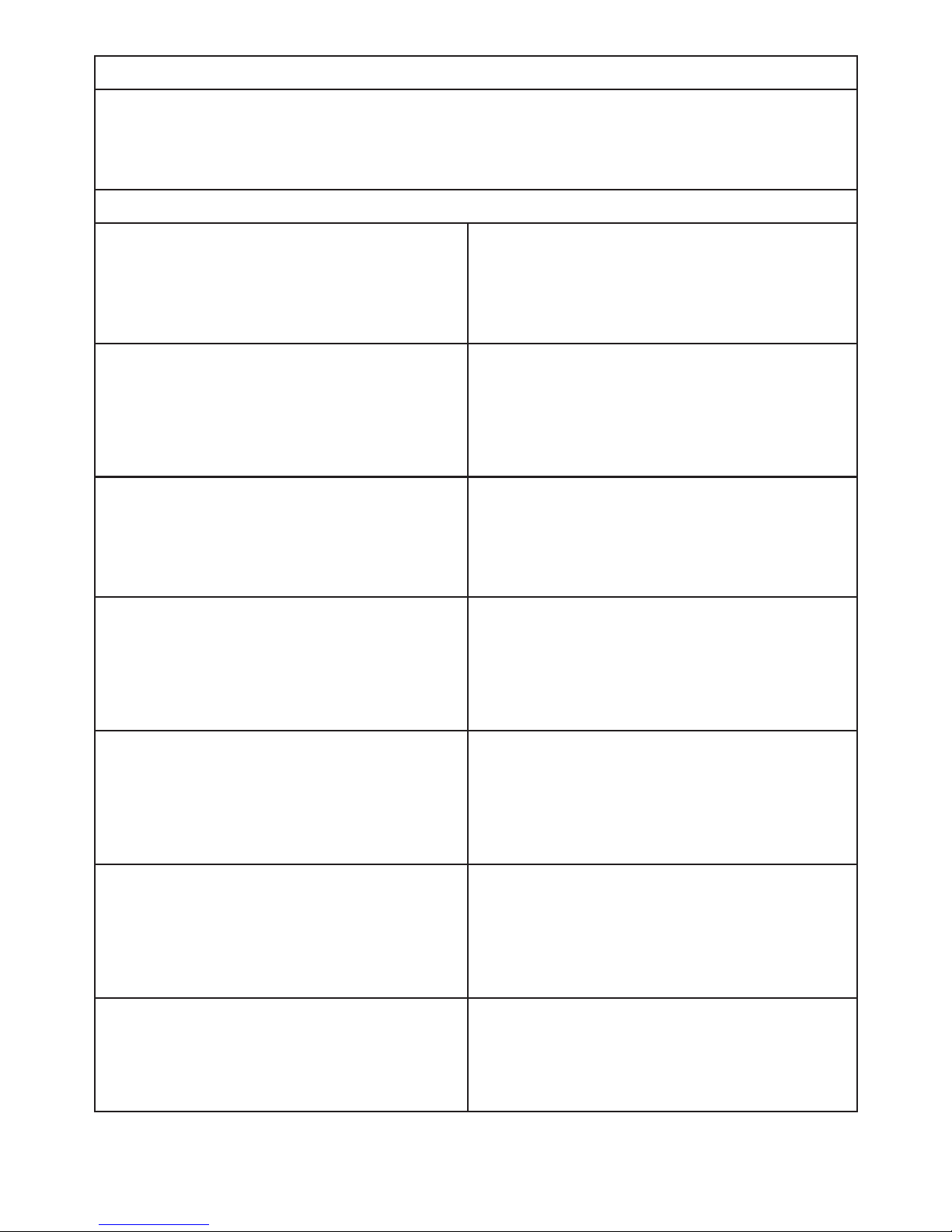
ViewSonic CD4233
Contact Information for Sales & Authorized Service (Centro Autorizado de Servicio) within Mexico:
Name, address, of manufacturer and importers:
México, Av. de la Palma #8 Piso 2 Despacho 203, Corporativo Interpalmas,
Col. San Fernando Huixquilucan, Estado de México
Tel: (55) 3605-1099
http://www.viewsonic.com/la/soporte/index.htm
NÚMERO GRATIS DE ASISTENCIA TÉCNICA PARA TODO MÉXICO: 001.866.823.2004
Hermosillo:
Distribuciones y Servicios Computacionales SA de CV.
Calle Juarez 284 local 2
Col. Bugambilias C.P: 83140
Tel: 01-66-22-14-9005
E-Mail: [email protected]
Villahermosa:
Compumantenimietnos Garantizados, S.A. de C.V.
AV. GREGORIO MENDEZ #1504
COL, FLORIDA C.P. 86040
Tel: 01 (993) 3 52 00 47 / 3522074 / 3 52 20 09
E-Mail: [email protected]
Puebla, Pue. (Matriz):
RENTA Y DATOS, S.A. DE C.V. Domicilio:
29 SUR 721 COL. LA PAZ
72160 PUEBLA, PUE.
Tel: 01(52).222.891.55.77 CON 10 LINEAS
E-Mail: [email protected]
Veracruz, Ver.:
CONEXION Y DESARROLLO, S.A DE C.V. Av.
Americas # 419
ENTRE PINZÓN Y ALVARADO
Fracc. Reforma C.P. 91919
Tel: 01-22-91-00-31-67
E-Mail: [email protected]
Chihuahua
Soluciones Globales en Computación
C. Magisterio # 3321 Col. Magisterial
Chihuahua, Chih.
Tel: 4136954
E-Mail: [email protected]
Cuernavaca
Compusupport de Cuernavaca SA de CV
Francisco Leyva # 178 Col. Miguel Hidalgo
C.P. 62040, Cuernavaca Morelos
Tel: 01 777 3180579 / 01 777 3124014
E-Mail: [email protected]
Distrito Federal:
QPLUS, S.A. de C.V.
Av. Coyoacán 931
Col. Del Valle 03100, México, D.F.
Tel: 01(52)55-50-00-27-35
E-Mail : [email protected]
Guadalajara, Jal.:
SERVICRECE, S.A. de C.V.
Av. Niños Héroes # 2281
Col. Arcos Sur, Sector Juárez
44170, Guadalajara, Jalisco
Tel: 01(52)33-36-15-15-43
E-Mail: [email protected]
Guerrero Acapulco
GS Computación (Grupo Sesicomp)
Progreso #6-A, Colo Centro
39300 Acapulco, Guerrero
Tel: 744-48-32627
Monterrey:
Global Product Services
Mar Caribe # 1987, Esquina con Golfo Pérsico
Fracc. Bernardo Reyes, CP 64280
Monterrey N.L. México
Tel: 8129-5103
E-Mail: [email protected]
MERIDA:
ELECTROSER
Av Reforma No. 403Gx39 y 41
Mérida, Yucatán, México CP97000
Tel: (52) 999-925-1916
E-Mail: [email protected]
Oaxaca, Oax.:
CENTRO DE DISTRIBUCION Y
SERVICIO, S.A. de C.V.
Murguía # 708 P.A., Col. Centro, 68000, Oaxaca
Tel: 01(52)95-15-15-22-22
Fax: 01(52)95-15-13-67-00
E-Mail. [email protected]
Tijuana:
STD
Av Ferrocarril Sonora #3780 L-C
Col 20 de Noviembre
Tijuana, Mexico
FOR USA SUPPORT:
ViewSonic Corporation
381 Brea Canyon Road, Walnut, CA. 91789 USA
Tel: 800-688-6688 (English); 866-323-8056 (Spanish);
Fax: 1-800-685-7276
E-Mail: http://www.viewsonic.com
4.3: ViewSonic Mexico Limited Warranty LTV_LW02 Rev. 1A 06-25-07
47
Page 50

 Loading...